Motherboard P5GPL-X SE
E2368 First Edition January 2006 Copyright © 2006 ASUSTeK COMPUTER INC. All Rights Reserved. No part of this manual, including the products and software described in it, may be reproduced, transmitted, transcribed, stored in a retrieval system, or translated into any language in any form or by any means, except documentation kept by the purchaser for backup purposes, without the express written permission of ASUSTeK COMPUTER INC. (“ASUS”).
Contents Notices................................................................................................. vi Safety information...............................................................................vii About this guide..................................................................................viii Typography.......................................................................................... ix P5GPL-X SE specifications summary.....................................................
Contents Chapter 2: BIOS setup 2.1 2.2 2.3 2.4 2.5 iv Managing and updating your BIOS......................................... 2-2 2.1.1 Creating a bootable floppy disk............................... 2-2 2.1.2 ASUS EZ Flash utility................................................ 2-3 2.1.3 AFUDOS utility......................................................... 2-4 2.1.4 ASUS CrashFree BIOS 2 utility................................. 2-6 2.1.5 ASUS Update utility.................................
Contents 2.6 2.7 2.5.4 ACPI APIC Support ................................................ 2-27 2.5.5 APM Configuration................................................. 2-28 2.5.6 Hardware Monitor................................................... 2-30 Boot menu........................................................................... 2-31 2.6.1 Boot Device Priority............................................... 2-32 2.6.2 Hard Disk Drives.....................................................
Notices Federal Communications Commission Statement This device complies with Part 15 of the FCC Rules. Operation is subject to the following two conditions: • This device may not cause harmful interference, and • This device must accept any interference received including interference that may cause undesired operation. This equipment has been tested and found to comply with the limits for a Class B digital device, pursuant to Part 15 of the FCC Rules.
Safety information Electrical safety • To prevent electrical shock hazard, disconnect the power cable from the electrical outlet before relocating the system. • When adding or removing devices to or from the system, ensure that the power cables for the devices are unplugged before the signal cables are connected. If possible, disconnect all power cables from the existing system before you add a device.
About this guide This user guide contains the information you need when installing and configuring the motherboard. How this guide is organized This manual contains the following parts: • Chapter 1: Product introduction This chapter describes the features of the motherboard and the new technology it supports. This chapter also lists the hardware setup procedures that you have to perform when installing system components. It includes description of the jumpers and connectors on the motherboard.
Conventions used in this guide To make sure that you perform certain tasks properly, take note of the following symbols used throughout this manual. DANGER/WARNING: Information to prevent injury to yourself when trying to complete a task. CAUTION: Information to prevent damage to the components when trying to complete a task. IMPORTANT: Instructions that you MUST follow to complete a task. NOTE: Tips and additional information to help you complete a task.
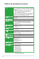
P5GPL-X SE specifications summary CPU LGA775 socket for Intel® Pentium® 4/Celeron® processors Supports Intel® single-core 65nm Intel® Pentium® 4/Celeron® processors (Refer to support.asus.
P5GPL-X SE specifications summary Overclocking ASUS CPU Lock Free Technology ASUS AI Overclocking (Intelligent CPU frequency tuner) CPU and Memory voltage adjustable SFS (Stepless Frequency Selection) from 100MHz up to 400MHz at 1MHz increment Adjustable FSB/DDR ratio. Fixed PCI/PCIe frequencies. ASUS C.P.R.
xii
This chapter describes the motherboard features and the new technologies it supports.
1.1 Welcome! Thank you for buying an ASUS® P5GPL-X SE motherboard! The motherboard delivers a host of new features and latest technologies, making it another standout in the long line of ASUS quality motherboards! Before you start installing the motherboard, and hardware devices on it, check the items in your package with the list below. 1.2 Package contents Check your motherboard package for the following items.
1.3 Special features 1.3.1 Product highlights Support Intel® 65nm Single-Core CPU This motherboard support Intel® single-core 65nm, Intel® Pentium® 4, and Intel® Celeron® processors. ASUS motherboard is the ideal solution to enhance the performance of new generation processors. Latest processor technology The motherboard comes with a 775-pin surface mount Land Grid Array (LGA) socket designed for the Intel® Pentium® 4 or Intel® Celeron® processor in the 775-land package.
Dual-channel DDR memory support Employing the Double Data Rate (DDR) memory technology, the motherboard supports up to 2GB of system memory using DDR400/333 DIMMs. The ultra-fast 400MHz memory bus delivers the required bandwidth for the latest 3D graphics, multimedia, and Internet applications. See page 1-16 for details. PCI Express™ interface The motherboard fully supports PCI Express, the latest I/O interconnect technology that speeds up the PCI bus.
Temperature, fan, and voltage monitoring The CPU temperature is monitored by the Winbond Super I/O to prevent overheating and damage. The system fan rotation per minute (RPM) is monitored for timely failure detection. The Winbond Super I/O monitors the voltage levels to ensure stable supply of current for critical components. 1.3.2 Innovative ASUS features CPU Lock Free This feature allows you to adjust the CPU multiplier to 14x.
1.4 Before you proceed Take note of the following precautions before you install motherboard components or change any motherboard settings. • Unplug the power cord from the wall socket before touching any component. • Use a grounded wrist strap or touch a safely grounded object or to a metal object, such as the power supply case, before handling components to avoid damaging them due to static electricity • Hold components by the edges to avoid touching the ICs on them.
1.5 Motherboard overview Before you install the motherboard, study the configuration of your chassis to ensure that the motherboard fits into it. Make sure to unplug the power cord before installing or removing the motherboard. Failure to do so can cause you physical injury and damage motherboard components. 1.5.1 Placement direction When installing the motherboard, make sure that you place it into the chassis in the correct orientation.
1.5.3 Motherboard layout 18.2cm (7.2in) PS/2KBMS T: Mouse KBPWR B: Keyboard ATX12V PARALLEL PORT LAN_USB34 USBPW1 ® Intel 915PL PRI_IDE Top:Line In Center:Line Out Below:Mic In CPU_FAN Marvell 88E8001 30.5cm (12.
1.6 Central Processing Unit (CPU) The motherboard comes with a surface mount LGA775 socket designed for the Intel® Pentium® 4 processor in the 775-land package. 1.6.1 • Your boxed Intel® Pentium® 4 LGA775 processor package should come with installation instructions for the CPU, fan and heatsink assembly. If the instructions in this section do not match the CPU documentation, follow the latter.
2. Press the load lever with your thumb (A) and move it to the left (B) until it is released from the retention tab. Retention tab PnP Cap A Load lever B This side of the cam box should face you. To prevent damage to the socket pins, do not remove the PnP cap unless you are installing a CPU. 3. Lift the load lever in the direction of the arrow to a 135º angle. 4.
6. Close the load plate (A), then push the load lever (B) until it snaps into the retention tab. A B The CPU fits in only one correct orientation.
1.6.2 Installling the CPU heatsink and fan The Intel® Pentium® 4 LGA775 processor requires a specially designed heatsink and fan assembly to ensure optimum thermal condition and performance. • Install the motherboard to the chassis before you install the CPU fan and heatsink assembly • When you buy a boxed Intel® Pentium® 4 processor, the package includes the CPU fan and heatsink assembly. If you buy a CPU separately, make sure that you use only Intel®‑certified multi‑directional heatsink and fan.
2. A B B A B A A B When the fan and heatsink assembly is in place, connect the CPU fan cable to the connector on the motherboard labeled CPU_FAN. GND CPU FAN PWR CPU FAN IN CPU FAN PWM 3. Push down two fasteners at a time in a diagonal sequence to secure the heatsink and fan assembly in place. CPU_FAN P5GPL-X ® P5GPL-X SE CPU fan connector Do not forget to connect the CPU fan connector! Hardware monitoring errors can occur if you fail to plug this connector.
1.6.3 Uninstalling the CPU heatsink and fan To uninstall the CPU heatsink and fan: 1-26 1. Disconnect the CPU fan cable from the connector on the motherboard. 2. Rotate each fastener counterclockwise. 3. Pull up two fasteners at a time in a diagonal sequence to disengage the heatsink and fan assembly from the motherboard.
4. Remove the heatsink and fan assembly from the motherboard. 5. Rotate each fastener clockwise to reset the orientation. When reset, each fastener should be oriented as shown, with the narrow groove directed outward.
1.7 System memory 1.7.1 Overview The motherboard comes with two 184-pin Double Data Rate (DDR) Dual Inline Memory Modules (DIMM) sockets. DIMM_B1 DIMM_A1 The following figure illustrates the location of the sockets: P5GPL-X ® P5GPL-X SE 184-pin DDR DIMM sockets 1.7.2 Memory Configurations You may install 256 MB, 512 MB and 1 GB unbuffered non‑ECC DDR DIMMs into the DIMM sockets using the memory configurations in this section.
Recommended memory configurations For dual-channel configuration, the total size of memory module(s) installed per channel must be the same to ensure optimum performance.
DDR400 Qualified Vendors List Size Vendor Model Brand Side(s) Component 256MB 512MB 256MB 512MB 256MB 512MB 256MB 256MB 256MB 256MB 512MB 512MB 512MB 512MB 512MB 512MB 512MB 256MB 256MB 256MB 256MB 256MB 256MB 256MB 256MB 512MB 256MB 512MB 256MB 512MB 256MB 256MB 256MB 256MB 256MB 512MB 512MB 256MB 512MB 256MB 512MB 256MB 512MB 256MB 256MB 512MB 512MB 256MB 256MB 512MB 512MB 256MB 256MB 512MB 512MB 256MB 512MB A DATA A DATA A DATA A DATA A DATA A DATA Aeneon APACER APACER BRAIN POWER CENTURY CENTURY
1.7.3 Installing a DIMM Make sure to unplug the power supply before adding or removing DIMMs or other system components. Failure to do so may cause severe damage to both the motherboard and the components. 1. Unlock a DIMM socket by pressing the retaining clips outward. 2. Align a DIMM on the socket such that the notch on the DIMM matches the break on the socket. 2 DDR DIMM notch 1 1 Unlocked retaining clip A DDR DIMM is keyed with a notch so that it fits in only one direction.
1.8 Expansion slots In the future, you may need to install expansion cards. The following sub‑sections describe the slots and the expansion cards that they support. Make sure to unplug the power cord before adding or removing expansion cards. Failure to do so may cause you physical injury and damage motherboard components. 1.8.1 Installing an expansion card To install an expansion card: 1.
1.8.
1.8.4 PCI slots The PCI slots support cards such as a LAN card, SCSI card, USB card, and other cards that comply with PCI specifications. The figure shows a LAN card installed on a PCI slot. 1.8.5 PCI Express x16 slot This motherboard supports PCI Express x16 graphic cards that comply with the PCI Express specifications. The figure shows a graphics card installed on the PCI Express x16 slot. 1.8.
1.9 1. Jumpers Clear RTC RAM (CLRTC) This jumper allows you to clear the Real Time Clock (RTC) RAM in CMOS. You can clear the CMOS memory of date, time, and system setup parameters by erasing the CMOS RTC RAM data. The onboard button cell battery powers the RAM data in CMOS, which include system setup information such as system passwords. To erase the RTC RAM: 1. Turn OFF the computer and unplug the power cord. 2. Remove the onboard battery. 3.
2. USB device wake-up (3-pin USBPW12, USBPW34, USBPW56, USBPW78) Set these jumpers to +5V to wake up the computer from S1 sleep mode (CPU stopped, DRAM refreshed, system running in low power mode) using the connected USB devices. Set to +5VSB to wake up from S3 and S4 sleep modes (no power to CPU, DRAM in slow refresh, power supply in reduced power mode). The USBPW1 jumpers are for the rear USB ports. The USBPW2 jumper is for the internal USB connectors that you can connect to additional USB ports.
3. Keyboard power (3-pin KBPWR) This jumper allows you to enable or disable the keyboard wake-up feature. Set this jumper to pins 2-3 (+5VSB) to wake up the computer when you press a key on the keyboard (the default is the Space Bar). This feature requires an ATX power supply that can supply at least 1A on the +5VSB lead, and a corresponding setting in the BIOS.
1.10 Connectors 1.10.1 Rear panel connectors 1 2 3 4 5 6 11 10 9 8 7 1. PS/2 mouse port (green). This port is for a PS/2 mouse. 2. Parallel port. This 25-pin port connects a parallel printer, a scanner, or other devices. 3. LAN (RJ-45) port. This port allows Gigabit connection to a Local Area Network (LAN) through a network hub. Refer to the table below for the LAN port LED indications.
7. USB 2.0 ports 3 and 4. These two 4-pin Universal Serial Bus (USB) ports are available for connecting USB 2.0 devices. 8. USB 2.0 ports 1 and 2. These two 4-pin Universal Serial Bus (USB) ports are available for connecting USB 2.0 devices. 9. Coaxial S/PDIF Out port. This port connects an external audio output device via a coaxial S/PDIF cable. 10. Serial connector. This 9-pin COM1 port is for serial devices. 11. PS/2 keyboard port (purple). This port is for a PS/2 keyboard. 1.10.
2. Floppy disk drive connector (34-1 pin FLOPPY) This connector is for the provided floppy disk drive (FDD) signal cable. Insert one end of the cable to this connector, then connect the other end to the signal connector at the back of the floppy disk drive. Pin 5 on the connector is removed to prevent incorrect cable connection when using an FDD cable with a covered Pin 5. FLOPPY P5GPL-X ® PIN 1 NOTE: Orient the red markings on the floppy ribbon cable to PIN 1.
4. Serial ATA connectors (7-pin SATA1, SATA2, SATA3, SATA4) These connectors are for the Serial ATA signal cables for Serial ATA hard disk drives.
5. Chassis intrusion connector (4-1 pin CHASSIS) This connector is for a chassis-mounted intrusion detection sensor or switch. Connect one end of the chassis intrusion sensor or switch cable to this connector. The chassis intrusion sensor or switch sends a high-level signal to this connector when a chassis component is removed or replaced. The signal is then generated as a chassis intrusion event. By default, the pins labeled “Chassis Signal” and “Ground” are shorted with a jumper cap.
7. Optical drive audio connector (4-pin CD) P5GPL-X Right Audio Channel Ground Ground Left Audio Channel This connector is for the 4-pin audio cable that connects to the audio connector at the back of the optical drive.
8. ATX power connectors (24-pin EATXPWR, 4-pin ATX12V) These connectors are for an ATX power supply. The plugs from the power supply are designed to fit these connectors in only one orientation. Find the proper orientation and push down firmly until the connectors completely fit. • It is recommended that you use an ATX 12 V Specification 2.0‑compliant power supply unit (PSU) with a minimum of 350 W power rating. This PSU type has 24-pin and 4-pin power plugs.
9. Front panel audio connector (10-1 pin AAFP) This connector is for a chassis-mounted front panel audio I/O module that supports either HD Audio or legacy AC ‘97 audio standard. Connect one end of the front panel audio I/O module cable to this connector.
11. System panel connector (20-pin PANEL) This connector supports several chassis-mounted functions. +5V Ground Ground Speaker SPEAKER IDE_LED P5GPL-X SE System panel connector Reset Ground PANEL PWR Ground ® IDE_LED+ IDE_LED- P5GPL-X PLED- PLED+ PLED Reset PWRSW The sytem panel connector is color-coded for easy connection. Refer to the connector description below for details. 1-34 • System power LED (Green 3-pin PLED) This 3-pin connector is for the system power LED.
This chapter tells how to change the system settings through the BIOS Setup menus. Detailed descriptions of the BIOS parameters are also provided.
2.1 Managing and updating your BIOS The following utilities allow you to manage and update the motherboard Basic Input/Output System (BIOS) setup. 1. ASUS AFUDOS (Updates the BIOS in DOS mode using a bootable floppy disk.) 2. ASUS EZ Flash (Updates the BIOS using a floppy disk during POST.) 3. ASUS CrashFree BIOS 2 (Updates the BIOS using a bootable floppy disk or the motherboard support CD when the BIOS file fails or gets corrupted.) 4. ASUS Update (Updates the BIOS in Windows® environment.
d. From the Open field, type D:\bootdisk\makeboot a: assuming that D: is your optical drive. e. Press , then follow screen instructions to continue. 2. Copy the original or the latest motherboard BIOS file to the bootable floppy disk. 2.1.2 ASUS EZ Flash utility The ASUS EZ Flash feature allows you to update the BIOS without having to go through the long process of booting from a floppy disk and using a DOS‑based utility.
2.1.3 AFUDOS utility The AFUDOS utility allows you to update the BIOS file in DOS environment using a bootable floppy disk with the updated BIOS file. This utility also allows you to copy the current BIOS file that you can use as backup when the BIOS fails or gets corrupted during the updating process. Copying the current BIOS To copy the current BIOS file using the AFUDOS utility: • Make sure that the floppy disk is not write-protected and has at least 600 KB free space to save the file.
Updating the BIOS file To update the BIOS file using the AFUDOS utility: 1. Visit the ASUS website (www.asus.com) and download the latest BIOS file for the motherboard. Save the BIOS file to a bootable floppy disk. Write the BIOS filename on a piece of paper. You need to type the exact BIOS filename at the DOS prompt. 2. Copy the AFUDOS utility (afudos.exe) from the motherboard support CD to the bootable floppy disk you created earlier. 3.
2.1.4 ASUS CrashFree BIOS 2 utility The ASUS CrashFree BIOS 2 is an auto recovery tool that allows you to restore the BIOS file when it fails or gets corrupted during the updating process. You can update a corrupted BIOS file using the motherboard support CD or the floppy disk that contains the updated BIOS file. • Prepare the motherboard support CD or the floppy disk containing the updated motherboard BIOS before using this utility.
Recovering the BIOS from the support CD To recover the BIOS from the support CD: 1. Remove any floppy disk from the floppy disk drive, then turn on the system. 2. Insert the support CD to the optical drive. 3. The utility displays the following message and automatically checks the floppy disk for the original or updated BIOS file. Bad BIOS checksum. Starting BIOS recovery... Checking for floppy...
2.1.5 ASUS Update utility The ASUS Update is a utility that allows you to manage, save, and update the motherboard BIOS in Windows® environment. The ASUS Update utility allows you to: • Save the current BIOS file • Download the latest BIOS file from the Internet • Update the BIOS from an updated BIOS file • Update the BIOS directly from the Internet, and • View the BIOS version information. This utility is available in the support CD that comes with the motherboard package.
Updating the BIOS through the Internet To update the BIOS through the Internet: 1. Launch the ASUS Update utility from the Windows® desktop by clicking Start > Programs > ASUS > ASUSUpdate > ASUSUpdate. The ASUS Update main window appears. 2. Select Update BIOS from the Internet option from the drop‑down menu, then click Next. ASUS P5GPL-X SE 3. Select the ASUS FTP site nearest you to avoid network traffic, or click Auto Select. Click Next.
4. From the FTP site, select the BIOS version that you wish to download. Click Next. 5. Follow the screen instructions to complete the update process. The ASUS Update utility is capable of updating itself through the Internet. Always update the utility to avail all its features. Updating the BIOS through a BIOS file To update the BIOS through a BIOS file: 2-44 1. Launch the ASUS Update utility from the Windows® desktop by clicking Start > Programs > ASUS > ASUSUpdate > ASUSUpdate.
2.2 BIOS setup program This motherboard supports a programmable firmware chip that you can update using the provided utility described in section “2.1 Managing and updating your BIOS.” Use the BIOS Setup program when you are installing a motherboard, reconfiguring your system, or prompted to “Run Setup”. This section explains how to configure your system using this utility. Even if you are not prompted to use the Setup program, you can change the configuration of your computer in the future.
2.2.1 BIOS menu screen Menu items Menu bar System Time System Date Legacy Diskette A Primary IDE Master Primary IDE Slave Third IDE Master Third IDE Slave Fourth IDE Master Fourth IDE Slave IDE Configuration Configuration fields General help [11:51:19] [Thu 05/07/2004] [1.44M, 3.5 in] Use [ENTER], [TAB] or [SHIFT-TAB] to select a field. :[ST320413A] :[Not Detected] :[Not Detected] :[Not Detected] :[Not Detected] :[Not Detected] Use [+] or [-] to configure system time.
2.2.4 Menu items The highlighted item on the menu bar displays the specific items for that menu. For example, selecting Main shows the Main menu items. The other items (Advanced, Power, Boot, and Exit) on the menu bar have their respective menu items. 2.2.5 System Time System Date Legacy Diskette A Language Primary IDE Master Primary IDE Slave Secondary IDE Master Secondary IDE Slave Third IDE Master Fourth IDE Master IDE Configuration [11:10:19] [Thu 03/27/2003] [1.44M, 3.
2.3 Main menu When you enter the BIOS Setup program, the Main menu screen appears, giving you an overview of the basic system information. Refer to section “2.2.1 BIOS menu screen” for information on the menu screen items and how to navigate through them. System Time System Date Legacy Diskette A Primary IDE Master Primary IDE Slave Third IDE Master Third IDE Slave Fourth IDE Master Fourth IDE Slave IDE Configuration [11:51:19] [Thu 05/07/2004] [1.44M, 3.
2.3.4 Primary, Third and Fourth IDE Master/Slave While entering Setup, the BIOS automatically detects the presence of IDE devices. There is a separate sub-menu for each IDE device. Select a device item then press to display the IDE device information. Primary IDE Master Device : Hard Disk Vendor : ST320413A Size : 20.
PIO Mode [Auto] Selects the PIO mode. Configuration options: [Auto] [0] [1] [2] [3] [4] DMA Mode [Auto] Selects the DMA mode. Configuration options: [Auto] [SWDMA0] [SWDMA1] [SWDMA2] [MWDMA0] [MWDMA1] [MWDMA2] [UDMA0] [UDMA1] [UDMA2] [UDMA3] [UDMA4] [UDMA5] [UDMA6] SMART Monitoring [Auto] Sets the Smart Monitoring, Analysis, and Reporting Technology. Configuration options: [Auto] [Disabled] [Enabled] 32Bit Data Transfer [Disabled] Enables or disables 32-bit data transfer.
Onboard IDE Operate Mode [Enhanced Mode] Disables or allows selection of the IDE operation mode depending on the installed operating system (OS). Set to [Enhanced Mode] if you are using native OS including Windows® 2000/XP. Configuration options: [Disabled] [Compatible Mode] [Enhanced Mode] Enhanced Mode Support On [S-ATA] Allows you to use native OS on Serial ATA and Parallel ATA ports. It is recommend that you do not change the default setting for better OS compatibility.
2.3.6 System Information This menu gives you an overview of the general system specifications. The BIOS automatically detects the items in this menu. AMIBIOS Version : 0106 Build Date : 01/06/06 Processor Type Speed Count : Genuine Intel(R) CPU 3.
2.4 Advanced menu The Advanced menu items allow you to change the settings for the CPU and other system devices. Take caution when changing the settings of the Advanced menu items. Incorrect field values can cause the system to malfunction. JumperFree Configuration USB Configuration Configure CPU. CPU Configuration Chipset Onboard Devices Configuration PCI PnP 2.4.
CPU Frequency [XXX] Displays the frequency sent by the clock generator to the system bus and PCI bus. The value of this item is auto-detected by the BIOS. Use the <+> and <-> keys to adjust the CPU frequency. You can also type the desired CPU frequency using the numeric keypad. The values range from 100 to 400. Refer to the table below for the correct Front Side Bus and CPU External Frequency settings.
2.4.2 USB Configuration The items in this menu allows you to change the USB-related features. Select an item then press to display the configuration options. USB Configuration Module Version - 2.24.0-10.4 USB Devices Enabled: None USB Function [Enabled] Legacy USB Support [Auto] USB 2.0 Controller [Enabled] USB 2.0 Controller Mode [HiSpeed] The Module Version and USB Devices Enabled items show the auto-detected values. If no USB device is detected, the item shows None.
2.4.3 CPU Configuration The items in this menu show the CPU-related information that the BIOS automatically detects. Configure Advanced CPU settings Manufacturer: Intel Brand String: Genuine Intel(R) CPU 3.
Enhanced C1 Control [Auto] When set to [Auto], the BIOS will automatically check the CPU’s capability to enable the C1E support. In C1E mode, the CPU power consumption is lower when idle. Configuration options: [Auto] [Disabled] Hardware Prefetcher [Enabled] Enables or disables the Hardware Prefetcher feature. Configuration options: [Disabled] [Enabled] Adjacent Cache Line Prefetch [Enabled] Enables or disables the Adjacent Cache Line Prefetch feature.
Advanced Chipset Settings Configure DRAM Timing by SPD [Enabled] When this item is enabled, the DRAM timing parameters are set according to the DRAM SPD (Serial Presence Detect). When disabled, you can manually set the DRAM timing parameters through the DRAM sub-items. The following sub-items appear when this item is Disabled. Configuration options: [Disabled] [Enabled] DRAM CAS# Latency [3 Clocks] Controls the latency between the SDRAM read command and the time the data actually becomes available.
PEG Root Control [Auto] Enables or disables the PCI Express Graphics root control. Configuration options: [Auto] [Disabled] [Enabled] Slot Power [Auto] Sets the slot operating power. Configuration options: [Auto] [Light] [Normal] [Heavy] [Heavier] 2.4.
ECP Mode DMA Channel [DMA3] Appears only when the Parallel Port Mode is set to [ECP]. This item allows you to set the Parallel Port ECP DMA. Configuration options: [DMA0] [DMA1] [DMA3] Parallel Port IRQ [IRQ7] Configuration options: [IRQ5] [IRQ7] Onboard Game/MIDI Port [Disabled] Allows you to select the Game Port address or to disable the port. Configuration options: [Disabled] [200/300] [200/330] [208/300] [208/330] 2.4.
PCI Latency Timer [64] Allows you to select the value in units of PCI clocks for the PCI device latency timer register. Configuration options: [32] [64] [96] [128] [160] [192] [224] [248] Allocate IRQ to PCI VGA [Yes] When set to [Yes], BIOS assigns an IRQ to PCI VGA card if the card requests for an IRQ. When set to [No], BIOS does not assign an IRQ to the PCI VGA card even if requested.
2.5.3 ACPI 2.0 Support [No] Allows you to add more tables for Advanced Configuration and Power Interface (ACPI) 2.0 specifications. Configuration options: [No] [Yes] 2.5.4 ACPI APIC Support [Enabled] Allows you to enable or disable the Advanced Configuration and Power Interface (ACPI) support in the Application-Specific Integrated Circuit (ASIC). When set to Enabled, the ACPI APIC table pointer is included in the RSDT pointer list. Configuration options: [Disabled] [Enabled] 2.5.
RTC Alarm Hour [12] Sets the RTC alarm hour. Use the plus (+) or minus (-) keys to adjust the values. Configuration options: [00] [01] ~ [23] RTC Alarm Minute [30] Sets the RTC alarm minute. Use the plus (+) or minus (-) keys to adjust the values. Configuration options: [00] [01] ~ [59] RTC Alarm Second [30] Sets the RTC alarm second. Use the plus (+) or minus (-) keys to adjust the values.
2.5.6 Hardware Monitor Hardware Monitor CPU Temperature [51ºC/122.5ºF] MB Temperature [41ºC/105.5ºF] CPU Fan Speed [3813 RPM] CPU Q-Fan Control [Disabled] Chassis Fan Speed [N/A] VCORE Voltage [ 1.320V] 3.3V Voltage [ 3.345V] 5V Voltage [ 5.094V] 12V Voltage [11.
CPU Target Temperature [xxxºC] Allows you to set the CPU temperature threshold when the CPU fan speed is increased to lower the CPU temperature. This item appears only when the CPU Q-Fan Control item is Enabled. The configuration options vary depending on the CPU installed. Chassis Fan Speed [xxxxRPM] or [N/A] The onboard hardware monitor automatically detects and displays the chassis fan speed in rotations per minute (RPM). If the fan is not connected to the chassis, the specific field shows N/A.
2.6.1 Boot Device Priority Boot Device Priority 1st Boot Device [1st FLOPPY DRIVE] 2nd Boot Device [PM-ST330620A] 3rd Boot Device [PS-ASUS CD-S360] 1st ~ xxth Boot Device [1st Floppy Drive] Select Screen Item These items specify the boot device priority sequence fromSelect the available Enter Go to Sub-screen devices. The number of device items that appears on F1 the screen Generaldepends Help F10 Save and Exit on the number of devices installed in the system.
Full Screen Logo [Enabled] This allows you to enable or disable the full screen logo display feature. Configuration options: [Disabled] [Enabled] Set this item to [Enabled] to use the ASUS MyLogo™ feature. Add On ROM Display Mode [Force BIOS] Sets the display mode for option ROM. Configuration options: [Force BIOS] [Keep Current] Bootup Num-Lock [On] Allows you to select the power-on state for the NumLock.
2.6.4 Security The Security menu items allow you to change the system security settings. Select an item then press to display the configuration options. Security Settings Supervisor Password User Password : Not Installed : Not Installed to change password. again to disabled password. Change Supervisor Password Change Supervisor Password Select Screen Select Item +Change Option F1 General Help F10 Save and Exit password.
After you have set a supervisor password, the other items appear to allow you to change other security settings.
Clear User Password Select this item to clear the user password. Password Check [Setup] When set to [Setup], BIOS checks for user password when accessing the Setup utility. When set to [Always], BIOS checks for user password both when accessing Setup and booting the system. Configuration options: [Setup] [Always] 2.7 Exit menu The Exit menu items allow you to load the optimal or failsafe default values for the BIOS items, and save or discard your changes to the BIOS items.
Exit & Discard Changes Select this option only if you do not want to save the changes that you made to the Setup program. If you made changes to fields other than System Date, System Time, and Password, the BIOS asks for a confirmation before exiting. Discard Changes This option allows you to discard the selections you made and restore the previously saved values. After selecting this option, a confirmation appears. Select Ok to discard any changes and load the previously saved values.
2-38 Chapter 2: BIOS setup
This chapter describes the contents of the support CD that comes with the motherboard package.
3.1 Installing an operating system This motherboard supports Windows® 2000/2003 Server/XP operating systems (OS). Always install the latest OS version and corresponding updates to maximize the features of your hardware. 3.2 • Motherboard settings and hardware options vary. Use the setup procedures presented in this chapter for reference only. Refer to your OS documentation for detailed information.
3.2.2 Drivers menu The drivers menu shows the available device drivers if the system detects installed devices. Install the necessary drivers to activate the devices. Intel Chipset Inf Update Program This item installs the Intel® Chipset INF Update Program. This driver enables Plug‑n-Play INF support for the Intel® chipset components on the motherboard. When installed to the target system, this driver provides the method for configuring the chipset components.
3.2.3 Utilities menu The Utilities menu shows the applications and other software that the motherboard supports. Marvell Yukon VCT Application Installs the Marvell Yukon VCT Application. ASUS PC Probe This smart utility monitors the fan speed, CPU temperature, and system voltages, and alerts you of any detected problems. This utility helps you keep your computer in healthy operating condition. ASUS Update The ASUS Update utility allows you to update the motherboard BIOS in a Windows® environment.
Anti-Virus utility The anti-virus application scans, identifies, and removes computer viruses. View the online help for detailed information. 3.2.4 Manuals menu The Manuals menu contains a list of supplementary user manuals. Click an item to open the folder of the user manual. Most user manual files are in Portable Document Format (PDF). Install the Adobe® Acrobat® Reader from the Utilities menu before opening a user manual file.
3.2.5 ASUS Contact information Click the Contact tab to display the ASUS contact information. You can also find this information on the inside front cover of this user guide.
The Appendix describes the CPU features that the motherboard supports.
A.1 Intel® EM64T • The motherboard is fully compatible with Intel® Pentium® 4 LGA775 processors running on 32-bit operating systems. • The motherboard comes with a BIOS file that supports EM64T. You can download the latest BIOS file from the ASUS website (www.asus. com/support/download/) if you need to update the BIOS file. See Chapter 2 for details. • Visit www.intel.com for more information on the EM64T feature. • Visit www.microsoft.com for more information on Windows® 64-bit OS.
A.2.2 Using the EIST To use the EIST feature: 1. Turn on the computer, then enter the BIOS Setup. 2. Go to the Advanced Menu, highlight CPU Configuration, then press . 3. Set the Intel(R) SpeedStep Technology item to [Automatic], then press . 4. Press to save your changes and exit the BIOS setup. 5. After the computer restarts, right click on a blank space on the desktop, then select Properties from the pop-up menu. 6.
A.3 Intel® Hyper-Threading Technology • The motherboard supports Intel® Pentium® 4 LGA775 processors with Hyper-Threading Technology. • Hyper-Threading Technology is supported under Windows® XP/2003 Server and Linux 2.4.x (kernel) and later versions only. Under Linux, use the Hyper-Threading compiler to compile the code. If you are using any other operating systems, disable the Hyper-Threading Techonology item in the BIOS to ensure system stability and performance.