使用手冊 Motherboard P5KC
T3155 1.00 版 2007 年 5 月發行 版權所有·不得翻印 © 2007 華碩電腦 本產品的所有部分,包括配件與軟體等,其所有權都歸華碩電腦公司(以 下簡稱華碩)所有,未經華碩公司許可,不得任意地仿製、拷貝、謄抄或轉 譯。本使用手冊沒有任何型式的擔保、立場表達或其它暗示。若有任何因本 使用手冊或其所提到之產品的所有資訊,所引起直接或間接的資料流失、利 益損失或事業終止,華碩及其所屬員工恕不為其擔負任何責任。除此之外, 本使用手冊所提到的產品規格及資訊僅供參考,內容亦會隨時更新,恕不另 行通知。本使用手冊的所有部分,包括硬體及軟體,若有任何錯誤,華碩沒 有義務為其擔負任何責任。 使用手冊中所談論到的產品名稱僅做識別之用,而這些名稱可能是屬於其 他公司的註冊商標或是版權。 本產品的名稱與版本都會印在主機板/顯示卡上,版本數字的編碼方式是 用三個數字組成,並有一個小數點做間隔,如 1.22、1.24 等...
目錄內容 安全性須知........................................................................................................................7 電氣方面的安全性...............................................................................................7 操作方面的安全性...............................................................................................7 關於這本使用手冊..........................................................................................................8 使用手冊的編排方式.............................................
目錄內容 2.4.3 安裝記憶體模組.................................................................................2-20 2.4.4 取出記憶體模組.................................................................................2-20 2.5 擴充插槽..............................................................................................................2-21 2.5.1 安裝擴充卡...........................................................................................2-21 2.5.2 設定擴充卡....................................................................
目錄內容 4.2.9 線上操作說明......................................................................................4-11 4.3 主選單(Main Menu)...................................................................................4-12 4.3.1 System Time [XX:XX:XXXX]...........................................................4-12 4.3.2 System Date [Day XX/XX/XXXX]..................................................4-12 4.3.3 Legacy Diskette A [1.44M, 3.5 in.]..............................................4-12 4.3.
目錄內容 5.2.1 執行驅動程式及公用程式光碟....................................................... 5-1 5.2.2 驅動程式選單(Drivers menu)..................................................... 5-2 5.2.3 公用程式選單(Utilities menu).................................................. 5-3 5.2.4 製作磁片選單........................................................................................ 5-5 5.2.5 使用手冊選單........................................................................................ 5-6 5.2.6 華碩的聯絡方式......................................
安全性須知 電氣方面的安全性 • 為避免可能的電擊造成嚴重損害,在搬動電腦主機之前,請先將電腦電 源線暫時從電源插槽中拔掉。 • 當您要加入硬體裝置到系統中或者要移除系統中的硬體裝置時,請務必 先連接該裝置的訊號線,然後再連接電源線。可能的話,在安裝硬體裝 置之前先拔掉電腦的電源供應器電源線。 • 當您要從主機板連接或拔除任何的訊號線之前,請確定所有的電源線已 事先拔掉。 • 在使用介面卡或擴充卡之前,我們建議您可以先尋求專業人士的協助。 這些裝置有可能會干擾接地的迴路。 • 請確定電源供應器的電壓設定已調整到本國/本區域所使用的電壓標準值。 若您不確定您所屬區域的供應電壓值為何,那麼請就近詢問當地的電力公 司人員。 • 如果電源供應器已損壞,請不要嘗試自行修復。請將之交給專業技術服 務人員或經銷商來處理。 操作方面的安全性 • 在您安裝主機板以及加入硬體裝置之前,請務必詳加閱讀本手冊所提供 的相關資訊。 • 在使用產品之前,請確定所有的排線、電源線都已正確地連接好。若您 發現有任何重大的瑕疵,請儘速聯絡您的經銷商。 • 為避免發生電氣短路情形,請務必將所有沒用到的螺絲、迴紋針及其他 零件收好,不要遺留在主
關於這本使用手冊 產品使用手冊包含了所有當您在安裝華碩 P5KC 主機板時所需用到的資 訊。 使用手冊的編排方式 使用手冊是由下面幾個章節所組成: • 第一章:產品介紹 您可以在本章節中發現諸多華碩所賦予 P5KC 主機板的優異特色。利 用簡潔易懂的說明讓您能很快地掌握 P5KC 的各項特性,當然,在本章 節中我們也會提及所有能夠應用在 P5KC 的新產品技術。 • 第二章:硬體裝置資訊 本章節描述所有您在安裝系統元件時必須完成的硬體安裝程序。詳細 內容有:處理器與記憶體安裝、跳線選擇區設定以及主機板的各種裝置 接頭。 • 第三章:開啟電源 本章節說明開啟電腦電源的順序以及電腦開機後所發出各種不同類型 嗶嗶聲的代表意義。 • 第四章:BIOS 程式設定 本章節描述如何使用 BIOS 設定程式中的每一個選單項目來更改系統 的組態設定。此外也會詳加介紹 BIOS 各項設定值的使用時機與參數設 定。 • 第五章:軟體支援 您可以在本章節中找到所有包含在華碩驅動程式及公用程式光碟中的 軟體相關資訊。 • 附錄 在本附錄中,將介紹關於本主機板所支援的 CPU 功能與技術。
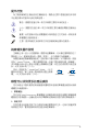
提示符號 為了能夠確保您正確地完成主機板設定,請務必注意下面這些會在本手冊 中出現的標示符號所代表的特殊含意。 警告:提醒您在進行某一項工作時要注意您本身的安全。 心:提醒您在進行某一項工作時要注意勿傷害到電腦主機板元 小 件。 要:此符號表示您必須要遵照手冊所描述之方式完成一項或多項 重 軟硬體的安裝或設定。 注意:提供有助於完成某項工作的訣竅和其他額外的資訊。 跳線帽及圖示說明 主機板上有一些小小的塑膠套,裡面有金屬導線,可以套住選擇區的任二 隻針腳(Pin)使其相連而成一通路(短路),本手冊稱之為跳線帽。 有關主機板的跳線帽使用設定,茲利用以下圖示說明。以下圖為例,欲設 定為「Jumper™ Mode」,需在選擇區的第一及第二隻針腳部份蓋上跳線帽, 本手冊圖示即以塗上底色代表蓋上跳線帽的位置,而空白的部份則代表空接 針。以文字表示為:[1-2]。 因此,欲設定為「JumperFree™ Mode」,以右 圖表示即為在「第二及第三隻針腳部份蓋上跳線 帽」,以文字表示即為:[2-3]。 1 Jumper Mode Jumper Free (Default) 哪裡可以找到更多的產
代理商查詢 華碩主機板在台灣透過聯強國際與精技電腦兩家代理商出貨,您請參考 下列範例圖示找出產品的 12 碼式序號標籤(下圖僅供參考),再至 http:// tw.asus.com/support/eService/querydist_tw.
P5KC 規格列表 中央處理器 支援採用 LGA775 規格插槽的 Intel® Core™2 Quad/ Core™2 Extreme/Core™2 Duo/Pentium ® Extreme/ Pentium® D/Pentium® 4 處理器 相容於 Intel® 05B/05A/06 處理器 支援 Intel® 新一代 45nm 多核心處理器 *請造訪 tw.asus.
P5KC 規格列表 華碩 AI Lifestyle 功 能 ASUS Quiet Thermal Solution: - ASUS AI Gear 2 - ASUS AI Nap - ASUS 無風扇散熱設計:熱導管散熱設計 - ASUS 無風扇散熱設計:Stack Cool 2 - ASUS Q-Fan 2 智慧型溫控風扇技術 ASUS Crystal Sound: - ASUS 噪音過濾功能(Noise Filer) ASUS EZ DIY: - ASUS Q-Connector 整合式訊號線接頭 - ASUS O.C. Profile 程式 - ASUS CrashFree BIOS 3 程式 - ASUS EZ Flash 2 程式 - ASUS AI Slot Detector 功能 其他功能 華碩 MyLogo 2 個性化應用程式 華碩獨家超頻功能 智慧型超頻工具: - AI NOS(無延遲超頻技術) - 華碩 AI Booster 應用程式 Precision Tweaker支援: - vCore:可調式 CPU 電壓,以每 0.
P5KC 規格列表 內建 I/O 裝置連接埠 3 x USB 2.0 連接埠可擴充六組 USB 2.0 連接埠 1 x 軟碟機連接插槽 1 x IDE 插槽 5 x Serial ATA 插座 1 x CPU / 2 x 機殼 / 1 x 電源 風扇插座 1 x IEEE 1394a 插座 1 x 序列埠(COM1) 1 x S/PDIF 數位音訊輸出插座 機殼開啟警示插座 前面板音源插座 內接音源插座(CD) 24-pin ATX 電源插座 2 x 4-pin ATX 12 V 電源插座 系統面板插座 BIOS 功能 8 Mb Flash ROM、AMI BIOS、PnP、DMI2.0、 WfM2.0、SM BIOS 2.3、ACPI 2.0a、華碩 EZ Flash 2、 華碩 CrashFree BIOS 3 管理功能 WfM 2.0、DMI 2.
您可以在本章節中發現諸多華碩所 賦予本主機板的優異特色,利用簡潔 易懂的說明,讓您能很快的掌握本主 機板的各項特性,當然,在本章節我 們也會提及所有能夠應用在本主機板 的新產品技術。 1 產品介紹
1 章節提綱 1.1 1.2 1.3 歡迎加入華碩愛好者的行列.................................... 1-1 產品包裝..................................................................... 1-1 特殊功能.....................................................................
1.1 歡迎加入華碩愛好者的行列! 再次感謝您購買此款華碩 P5KC 主機板! 本主機板的問世除了再次展現華碩對於主機板一貫具備的高品質、高效 能以及高穩定度的嚴苛要求,同時也添加了許多新的功能以及大量應用在它 身上的最新技術,使得 P5KC 主機板成為華碩優質主機板產品線中不可多得 的閃亮之星。 在您拿到本主機板包裝盒之後,請馬上檢查下面所列出的各項標準配件 是否齊全。 1.
1.3 特殊功能 1.3.
支援雙通道 DDR3 記憶體 本主機板支援 DDR3 資料傳輸率技術,DDR3 記憶體最大的特色在於支援 1333/1066/800 MHz 的資料傳輸率,可以符合像是 3D 繪圖、多媒體與網路 應用等更高的系統頻寬需求。雙通道 DDR3 記憶體架構可讓您系統的記憶體 頻寬倍增,可以顯著提升您系統平台的效能,並降低頻寬的瓶頸。 此外,本主機板沒有限制雙通道的記憶體容量,您可以安裝不同容量的記 憶體模組,同時享受單通道與雙通道功能。這項新功能可以將記憶體容量發 揮至最大效能。請參考 2-14 頁的說明。 支援 Serial ATA 3.
1.3.
華碩 Crystal Sound 這項功能可以提升語音、錄音等應用程式的效能,例如:Skype、線上遊 戲、視訊會議與影音錄製軟體等。 噪音過濾器(Noise Filter) 本功能可偵測重複的、持續不斷的噪音(non-voice 訊號),例如:電腦 風扇、空調或其他環境噪音,當您在錄音時,可有效降低干擾的噪音。 華碩 EZ DIY 華碩 EZ DIY 功能可以讓您更輕鬆地完成電腦零組件的組裝、BIOS 的升級 與備份您偏好之系統設定。 華碩 Q-Connector 透過華碩 Q-Connector,您只需要幾個簡單的步驟,即可連接機殼前面 板排線的連線。請參考 2-44 頁的說明。 華碩 O.C. Profile 本主機板擁有華碩 O.C.
1.3.3 華碩特殊功能 華碩 MyLogo2™ 個性化應用軟體 本主機板內附的 MyLogo2 軟體讓您從此遠離一成不變的開機換面。您可 以使用它來輕鬆更換電腦開機的畫面,除了可以隨心所欲地更換由華碩所提 供的好幾組圖案,當然也可依照您獨特的品味來創造屬於您個人才有的開機 畫面。請參考 4-31 頁的說明。 1.3.
本章節描述了所有您在安裝系統元 件時所必須完成的硬體安裝程序。 詳細內容有:處理器與記憶體、跳 線選擇區設定以及主機板的各種裝 置接頭。 2 硬體 裝置資訊
2 章節提綱 2.1 2.2 2.3 2.4 2.5 2.6 2.7 主機板安裝前............................................................. 2-1 主機板概觀................................................................. 2-2 中央處理器(CPU)................................................. 2-7 系統記憶體...............................................................2-14 擴充插槽...................................................................2-25 跳線選擇區...............................................................2-30 元件與周邊裝置的連接................................
2.1 主機板安裝前 主機板以及擴充卡都是由許多精密複雜的積體電路元件、整合性晶片等所 構成。而這些電子性零件很容易因靜電的影響而導致損壞,因此,在您動手更 改主機板上的任何設定之前,請務必先作好以下所列出的各項預防措施。 1. 在處理主機板上的內部功能設定時,您可以先拔掉電腦的電源 線。 2. 為避免產生靜電,在拿取任何電腦元件時除了可以使用防靜電 手環之外,您也可以觸摸一個有接地線的物品或者金屬物品像 電源供應器外殼等。 3. 拿取積體電路元件時請盡量不要觸碰到元件上的晶片。 4. 在您移除任何一個積體電路元件後,請將該元件放置在絕緣墊 上以隔離靜電,或者直接放回該元件的絕緣包裝袋中保存。 5.
2.2 主機板概觀 在您開始安裝之前,請確定您所購買的電腦主機機殼是否可以容納本主機 板,並且機殼內的主機板固定孔位是否能與本主機板的螺絲孔位吻合。 為方便在電腦主機機殼安裝或取出主機板,請務必先將電源供應器 移開!此外,取出主機板之前除了記得將電源供應器的電源線移除 之外,也要確定主機板上的警示燈號已熄滅方可取出。 2.2.1 主機板的擺放方向 當您安裝主機板到電腦主機機殼內時,務必確認置入的方向是否正確。主 機板 PS/2 滑鼠接頭、PS/2 鍵盤接頭、COM1 插槽以及音效插頭等的方向應 是朝向主機機殼的後方面板,而且您也會發現主機機殼後方面板會有相對應 的預留孔位。請參考下圖所示。 2.2.
2.2.
2.2.4 主機板構造圖 24.5cm (9.6in) CPU_FAN KB_USB56 PWR_FAN ATX12V DET_PCI2 JMB363 DET_X16_2 CD DET_PCI3 ALC883 DET_X1_1 PCIEX1_1 SPDIF_OUT Intel® ICH9 PCI1 PCI2 PCIEX16_2 PCI3 SATA4 SATA1 SATA3 SATA 2 CLRTC CHASSIS SB_PWR CR2032 3V Lithium Cell CMOS Power PRI_EIDE FLOPPY SATA_E2 PCIEX16_1 Super I/O DET_PCI1 P5KC VIA VT6308P LAN 30.5cm (12.
2.2.5 主機板元件說明 插槽 1. 2. 3. 4. 頁數 DDR2/DDR3 DIMM 插槽 PCI 插槽 PCI Express x 1 插槽 PCI Express x 16 插槽 2-14 2-27 2-27 2-27 開關與跳線選擇區 頁數 1. 2-30 Clear RTC RAM (3-pin CLRTC) 後側面板連接插槽 頁數 1. 2. 3. 4. 5. 6. 7. 8. 9. 10. 11. 12. 13. 14. 15.
2- 內部連接插槽 頁數 1. Floppy disk drive connector (34-1 pin FLOPPY) 2. IDE connector (40-1 pin PRI_EIDE) 3. ICH9 Serial ATA connectors (7-pin SATA1 [紅色], SATA2 [紅色], SATA3 [黑色], SATA4 [黑色] 4. JMicron JMB363 Serial ATA RAID connector (7-pin SATA_E2) 5. Digital audio connector (4-1 pin SPDIF_OUT) 6. USB connectors (10-1 pin USB78, USB910, USB1112) 7. IEEE 1394a port connector (10-1 pin IE1394_2) 8. Optical drive audio connector (4-pin CD) 9.
2.
2.3.1 安裝中央處理器 請依照以下步驟安裝處理器: 1. 找到位於主機板上的處理器插槽。 ® P5KC P5KC CPU Socket 775 在安裝處理器之前,請先將主機板上的處理器插槽面向您,並且 確認插槽的固定扳手位在您的左手邊。 2. 以手指壓下固定扳手並將其稍向左側推(A),這麼做可使扳手脫離固定 扣並鬆開 CPU 輔助安裝盒(B)。 固定扣 固定扳手 A 保護蓋 B 輔助安裝盒的這一 側需朝向您所在的 方向 CPU 安裝盒上的保護蓋是用以保護插槽上的接腳之用,因此只有 在 CPU 安裝妥當之後,才可將其移除。 3.
4. 請用手指將 CPU 安裝盒的上蓋掀起 (A),然後用手指從上蓋內側的缺 口將保護蓋推開移除(B)。 B A 安裝盒上蓋 校準點 5. 請確認 CPU 的金色三角 形標示是位在左下角的位 置,接著把 CPU 順著這 個方向安裝到主機板的插 槽上,並請確認 CPU 的 左上方的缺口與插槽上對 應的校準點是相吻合的。 CPU 校準缺口 金色三角形標示 CPU 只能以單一方向正確地安裝到主機板上的插槽。切記請勿用 力地將 CPU 以錯誤的方向安裝到插槽上,這麼做將可能導致 CPU 與插槽上的接腳損壞。 A 6. 將上蓋重新蓋上,接著將固定 扳手朝原方向推回並扣於固定 扣上。 7.
2.3.2 安裝散熱片和風扇 Intel LGA775 處理器需要搭配安裝經過特殊設計的散熱片與風扇,方能得 到最佳的散熱效能。 • 若您所購買的是盒裝 Intel 處理器,則產品包裝中即已內含有 一組專用的散熱片與風扇;若您所購買的是散裝的處理器,請 確認您所使用的 CPU 散熱器已通過 Intel 的相關認證。 • 盒裝 Intel LGA775 處理器包裝中的散熱器與風扇採用下推式 固定扣具,因此無須使用任何工具進行安裝。 • 若您所購買的是散裝的 CPU 散熱器與風扇,請在安裝之前確 認風扇散熱片上的金屬銅片或者是 CPU 上面有確實塗上散熱 膏。 在安裝處理器的風扇和散熱片之前,請先確認主機板已經安裝至 機殼上。 請依照下面步驟安裝處理器的散熱片和風扇: 1.
2. 將二組扣具以對角線的順序向下 推,使散熱器和風扇能正確地扣合 在主機板上。 B A A A B B A B 3.
2.3.3 卸除散熱器與風扇 請按照以下的步驟卸除散熱器和風扇: 1. 先將主機板上連接 CPU 散熱器的 電源線從 CPU_FAN 上移除。 2. 將每個扣具上的旋鈕以逆時鐘方向 旋轉,鬆開散熱器固定扣具。 3. 依照順序將扣具扳離主機板上的散 熱器插孔,採對角線方式移除,例 如:先移除 A,再移除 B;或是先 移除 B,再移除 A。 A B B A 4.
5.
2.4 系統記憶體 2.4.
• 這個晶片組的官方資料中支援至 DDR3 1066/800MHz,但由於 擁有華碩 Super Memspeed 技術,本主機板支援至 1333MHz, 並提供更多的比率設定選項,請參考下表的說明。 FSB DDR3 1600 1600 1333 1200 1333 1000 800 1333 1111 1000 1066 833 889 • 這個晶片組的官方資料中支援至 DDR2-800MHz,但由於擁有華 碩 Super Memspeed 技術,本主機板支援至 DDR2-1066MHz, 並提供更多的比率設定選項,請參考下表的說明。 FSB 1333 1333 1333 1066 1066 1066 DDR2 1066* 800 667 1066* 800 667 • 若是所安裝的 DDR2-1066 記憶體模組,其 SPD 為 DDR2800,請確認 BIOS 程式設定中的 DRAM Frequency 項目設定 為 [DDR2-1066MHz]。請參考「4.4.1 JumperFree 設定」一節 的說明。 2.4.
建議的記憶體設定(DDR3) 模式 單通道 雙通道 插槽 DDR3_DIMM_A1 DDR3_DIMM_B1 安裝 - - 安裝 安裝 安裝 • 您可以在 Channel A 與 Channel B 安裝不同容量的記憶體模組, 在雙通道設定中,系統會偵測較低容量通道的記憶體容量。任 何在較高容量通道的其他記憶體容量,會被偵測為單通道模式 執行。 • 在本主機板請使用相同 CL(CAS-Latency 行位址控制器延遲時 間)值記憶體模組。建議您使用同一廠商所生產的相同容量型 號之記憶體。請參考記憶體合格商供應列表。 ‧ 本主機板不支援 128Mb 晶片或雙面 x16 的記憶體模組。 DDR2 記憶體插槽: ‧ 在 DDR2 記憶體插槽上,由於晶片組資源配置的關係,當您安 裝四條 2GB 的記憶體模組,系統將會偵測到少於 8GB 的總記 憶體。 • 當您安裝四條 1GB 的記憶體模組,系統將會偵測到少於 3GB 的總記憶體,這是因為位址空間配置給其他功能。這項限制會 發生在 Windows XP/Vista 32-bit 版本作業系統,這是由於其不 支援 PAE(實體位址延伸)模式。 ‧
DDR3 記憶體插槽: • 當您安裝二條 2GB 的記憶體模組,系統將會偵測到少於 3GB 的總記憶體,這是因為位址空間配置給其他功能。這項限制會 發生在 Windows XP/Vista 32-bit 版本作業系統,這是由於其不 支援 PAE(實體位址延伸)模式。 ‧ 若您安裝 Windows XP/Vista 32-it 版本作業系統,我們建議您 安裝少於 3GB 的總記憶體。 ‧ 有些舊版的 DDR2-800 記憶體模組不符合 Intel 的內部中斷電 阻設計(On-Die-Termination,ODT)條件需求,因此會自動以 DDR2-667 的效能來執行。若是遇到這樣的情況,請向您使用 的記憶體供應商聯繫來確認 ODT 數值。 ‧ 由於晶片組的限制,DDR2-800 CL=4 在預設值中會降至以 DDR2-667 執行,若您想要在較低延遲的狀態下運作,請手動 調整記憶體時脈。 華碩 P5KC 主機板使用手冊 2-17
P5KC 主機板合格供應商列表(QVL) DDR3-1333 MHz 記憶體 插槽 容量 廠商 晶片型號 CL 晶片廠商 SS/ DS 型號 A* B* 512MB ELPIDA J5308BASE-DG-E 8 ELPIDA SS EBJ51UD8BAFA-DG-E • • 512MB Qimonda IDSH51-03A1F1C-13H 9 QIMONDA SS IMSH51U03A1F1C-13H • • 1024MB Qimonda IDSH51-03A1F1C-13H 9 QIMONDA DS IMSH1GU13A1F1C-13H • • P5KC 主機板合格供應商列表(QVL) DDR3-1066 MHz 記憶體 插槽 容量 廠商 晶片型號 CL 晶片廠商 SS/ DS 型號 1024MB Qimonda IDSH51-03A1F1C-10F N/A QIMONDA DS IMSH1GU13A1F1C-10F • 512MB NANYA NT5CB64M8AN-BE N/A NANYA
P5KC 主機板合格供應商列表(QVL) DDR2-1066 MHz 記憶體插槽 容量 廠商 SS/ DS 型號 A* B* C* 1024MB CORSAIR DS XMS8505v1.1 / 0616126-12 • • • 1024MB CORSAIR DS CM2X1024-8500 • • • 1024MB Kingston SS KHX9600D2 / 1G 9905316-069.A00LF / 2.3-2.35v • • • DS OCZ2P10002GK/PC2 8000 /1G EL Dual CH/PlatinumXTC • • • DS OCZ2P10002GK/PC2 8000 /1G EL Dual CH/Gold XTC • • • 1024MB OCZ 1024MB OCZ 當您安裝 SPD 是 DDR2-800 的 DDR2-1066 記憶體,請確認在 BIOS 程式的 DRAM Frequency 項目設定為 [DDR2-1066MHz]。請參考「 4.4.
2.4.3 安裝記憶體模組 安裝/移除記憶體模組或其他的系統元件之前,請先暫時拔出電腦 的電源線。如此可避免一些會對主機板或元件造成嚴重損壞的情 況發生。 2 請依照下面步驟安裝記憶體模組: 1. 先將記憶體模組插槽兩端 的白色固定卡榫扳開。 2. 將記憶體模組的金手指對 齊記憶體模組插槽的溝 槽,並且在方向上要注意 金手指的缺口要對準插槽 的凸起點。 記憶體模組缺口 3 1 1 3. 最後緩緩將記憶體模組插 入插槽中,若無錯誤,插 槽兩端的白色卡榫會因記 憶體模組置入而自動扣到 記憶體模組兩側的凹孔 中。 往外扳開記憶體 模組插槽兩端的 白色卡榫 • 由於 DDR2/DDR3 DIMM 記憶體模組金手指部份均有缺口設計, 因此只能以一個固定方向安裝到記憶體模組插槽中。安裝時僅 需對準金手指與插槽中的溝槽,再輕輕置入記憶體模組即可。 請勿強制插入以免損及記憶體模組。 • DDR3 記憶體插槽並不支援 DDR 與 DDR2 記憶體模組,請勿 將 DDR 或 DDR2 記憶體模組安裝至 DDR3 記憶體插槽上。 2.4.4 取出記憶體模組 請依照以下步驟取出記憶體模組: 1.
2.5 擴充插槽 為了因應未來會擴充系統機能的可能性,本主機板提供了擴充插槽,在接 下來的次章節中,將會描述主機板上這些擴充插槽的相關資訊。 安裝/移除任何擴充卡之前,請暫時先將電腦的電源線拔出。如此 可免除因電氣殘留於電腦中而發生的意外狀況。 2.5.1 安裝擴充卡 請依照下列步驟安裝擴充卡: 1. 在安裝擴充卡之前,請先詳讀該擴充卡的使用說明,並且要針對該卡作 必要的硬體設定變更。 2. 鬆開電腦主機的機殼蓋並將之取出(如果您的主機板已經放置在主機 內)。 3. 找到一個您想要插入新擴充卡的空置插槽,並以十字螺絲起子鬆開該插 槽位於主機背板的金屬擋板的螺絲,最後將金屬擋板移出。 4. 將擴充卡上的金手指對齊主機板上的擴充槽,然後慢慢地插入槽中,並 以目視的方法確認擴充卡上的金手指已完全沒入擴充槽中。 5. 再用剛才鬆開的螺絲將擴充卡金屬擋板鎖在電腦主機背板以固定整張 卡。 6. 將電腦主機的機殼蓋裝回鎖好。 2.5.2 設定擴充卡 在安裝好擴充卡之後,接著還須藉由軟體設定來調整該擴充卡的相關設 定。 1.
2.5.3 指定中斷要求 標準中斷要求使用一覽表 IRQ 0 1 2 3 4 5 6 7 8 9 10 11 12 13 14 優先權 1 2 – 11 12 13 14 3 4 5 6 7 8 9 10 指定功能 系統計時器 鍵盤控制器 重新指派給 IRQ#9 預留給 PCI 裝置使用* 通訊連接埠 (COM1)* 預留給 PCI 裝置使用* 標準軟式磁碟機控制卡 系統 CMOS/即時時鐘 預留給 PCI 裝置使用* 預留給 PCI 裝置使用* 預留給 PCI 裝置使用* PS/2 相容滑鼠連接埠* 數值資料處理器 第一組 IDE 通道 第二組 IDE 通道 *:這些通常是留給 PCI 介面卡使用。 本主機板使用的中斷要求一覽表 第 1 組 PCI 插槽 第 2 組 PCI 插槽 第 3 組 PCI 插槽 LAN(L1) SATA(363) 第一組 PCIE x16 第二組 PCIE x16 第一組 USB 控制器 第二組 USB 控制器 第三組 USB 控制器 第四組 USB 控制器 第五組 USB 控制器 第一組 USB 2.0 第二組 USB 2.
2.5.4 PCI 介面卡擴充插槽 本主機板配置 32 位元的 PCI 介 面卡擴充插槽,舉凡網路卡、SCSI 卡、音效卡、USB 卡等符合 PCI 介 面規格者,都可以使用在些 PCI 介 面卡擴充插槽。下面這一張圖示展示 PCI 介面網路卡放置在 PCI 介面卡擴 充插槽的情形。 2.5.5 PCI Express x1 介面卡插槽 本主機板提供支援 x1 規格的 PCI Express 介面卡插槽。這一張圖示展 示網路卡安裝在 PCI Express x1 介 面卡擴充插槽的情形。 2.5.
建議您將 VGA 顯示卡安裝在主要的(primary) PCI Express 插槽 (藍色),將其他的 PCI Express 裝置安裝在 Universal PCI-E 插 槽(黑色)。 Primary PCI Express x16 插槽 主要的(primary) PCI Express x16 插槽支援安裝 PCI Express x16 繪圖顯 示卡,並與 PCI Express 規格相容。 Universal PCI-E 插槽(最大 x4 模式) 本主機板支援最高傳輸速率達 2 GB/s 的 Universal PCI-E 插槽。本插槽的 頻率會依照所安裝的 PCI Express 介面卡而改變。請參考下表與 4-23 頁的 說明。 下表顯示將二張顯示卡安裝在 primary PCI Express x16 與 Universal PCI-E 插槽的情形。 當您安裝二張 VGA 顯示卡時,建議您將後側機殼的風扇排現連 接至主機板上標示有 CHA_FAN1 的插座,來獲得更好的散熱環 境。請參考 2-36 中插座的位置。 Universal PCI Express 插槽選項 PCI Expre
2.5.
2.6 跳線選擇區 1. CMOS 組態資料清除(CLRTC) 在主機板上的 CMOS 記憶體中記載著正確的時間與系統硬體組態等資 料,這些資料並不會因電腦電源的關閉而遺失資料與時間的正確性,因 為這個 CMOS 的電源是由主機板上的鋰電池所供應。 想要清除這些資料,可以依照下列步驟進行: 1. 關閉電腦電源,拔掉電源線; 2. 移除主機板上的電池; 3. 將 CLRTC1 跳線帽由 [1-2](預設值)改為 [2-3] 約五∼十秒鐘(此 時即清除 CMOS 資料),然後再將跳線帽改回 [1-2]; 4. 將電池安裝回主機板; 5. 上電源線,開啟電腦電源; 6. 當 開機步驟正在進行時按著鍵盤上的 <Del> 鍵進入 BIOS 程式畫 面重新設定 BIOS 資料。 7.
2.7 元件與周邊裝置的連接 2.7.1 後側面板連接埠 1 15 3 2 14 13 12 4 11 5 6 7 10 9 8 1. PS/2 鍵盤連接埠(紫色):將 PS/2 鍵盤插頭連接到此埠。 2. S/PDIF 同軸排線輸出接頭:這組接頭可以連接使用同軸排線的外接式音 效輸出裝置。 3. IEEE 1394a 連接埠:這組 IEEE 1394a 連接埠可以連接傳輸速率更高的影 音裝置、儲存設備、掃描器或是其他可攜式裝置。 4. LAN(RJ-45)網路連接埠:這組連接埠可經 Gigabit 網路線連接至 LAN 網路。請參考下表中各燈號的說明。 網路指示燈之燈號說明 ACT/LINK SPEED 指示燈 指示燈 Activity/Link 速度指示燈 狀態 描述 狀態 描述 關閉 沒有連線 關閉 連線速度 10 Mbps 橘色燈號 連線 橘色燈號 連線速度 100 Mbps 閃爍 資料傳輸中 綠色燈號 連線速度 1 Gbps 網路連接埠 5.
在 2、4、6、8 聲道音效設定上,音效輸出、音效輸入與麥克風接 頭的功能會隨著聲道音效設定的改變而改變,如下頁表格所示。 二、四、六或八聲道音效設定 接頭 耳機/二聲道喇 叭輸出 四聲道喇叭 輸出 六聲道喇叭輸出 八聲道喇叭輸出 淺藍色 聲音輸入端 聲音輸入端 聲音輸入端 聲音輸入端 草綠色 聲音輸出端 前置喇叭輸出 前置喇叭輸出 前置喇叭輸出 粉紅色 麥克風輸入端 麥克風輸入端 麥克風輸入端 麥克風輸入端 中央聲道/重低音 喇叭輸出 橘色 – – 中央聲道/重低音 喇叭輸出 黑色 – 後置喇叭輸出 後置喇叭輸出 後置喇叭輸出 灰色 – – - 側邊喇叭輸出 11. USB 2.0 裝置連接埠(1 和 2):這二組 4-pin 通用序列匯流排(USB) 連接埠可連接到使用 USB 2.0 介面的硬體裝置。 12.
• 請勿將不同的插頭插入這個外接式 SATA 連接埠。 • 當您設定為 RAID 0 或 JBOD 時,請不要將外接式 Serial ATA 裝置拔起。 13. USB 2.0 裝置連接埠(3 和 4):這二組 4-pin 通用序列匯流排(USB) 連接埠可連接到使用 USB 2.0 介面的硬體裝置。 14. S/PDIF 光纖排線輸出接頭:這組接頭可以連接使用同軸排線的外接式音 效輸出裝置。 15. USB 2.0 裝置連接埠(5 和 6):這二組 4-pin 通用序列匯流排(USB) 連接埠可連接到使用 USB 2.
2.7.2 內部連接埠 1. 軟碟機連接插槽(34-1 pin FLOPPY) 這個插槽用來連接軟式磁碟機的排線,而排線的另一端可以連接一部軟 式磁碟機。軟式磁碟機插槽第五腳已被故意折斷,而且排線端的第五個孔 也被故意填塞,如此可以防止在組裝過程中造成方向插反的情形。 PIN 1 FLOPPY ® P5KC P5KC Floppy disk drive connector 2-30 第二章:硬體裝置資訊 NOTE: Orient the red markings on the floppy ribbon cable to PIN 1.
2.
3.
4. JMicron JMB363 Serial ATA RAID 裝置連接插槽(7-pin SATA_E2) 這個插槽可使用 Serial ATA 排線來支援連接 Serial ATA 硬碟,若要設 定 RAID 0、RAID 1 或 JBOD 功能,將內接式 Serial ATA 硬碟連接至本 插槽,將外接式 Serial ATA 硬碟連接至外接式 SATA 連接埠。 在 BIOS 程式中 JMicron JMB363 Controller 項目的預設值為 [IDE], 當設定為 [RAID] 時,可以用來建立 RAID 陣列。請參考「5.4.3 JMicron RAID 設定」一節的說明。若將本項目設定為 [AHCI], 則可安裝支援有 NCQ 功能的硬碟機。請參考「4.4.
5. 數位音效連接排針(4-1 pin SPDIF_OUT) 這組排針是用來連接 S/PDIF 數位音效模組,您可以利用這組排針以 S/PDIF 音效訊號線連接到音效裝置的數位音訊輸出端,使用數位音訊輸 出來代替傳統的類比音訊輸出。 SPDIF_OUT + V P5KC SPDIFOUT GND ® P5KC Digital audio connector S/PDIF 模組為選購配備,請另行購買。 6. USB 擴充套件排線插槽(10-1 pin USB78, USB 910, USB1112) 這些 USB 擴充套件排線插槽支援 USB 2.0 規格,傳輸速率最高達 480 Mbps,比 USB 1.
7. IEEE 1394 連接插槽(10-1 pin IE1394_2) 這組插槽可以連接 IEEE 1394a 序列連接排線,用來連接 IEEE 1394a 模組。將 10-1 pin 端的排線(紅色)安裝至插槽上,將 IEEE 1394a 模 組安裝在機殼的背面。 ® P5KC GND +1 V TPB1GND TPA1- IE1 _ +1 V TPB1+ GND TPA1+ PIN 1 P5KC IEEE 1394a connector 請勿將 USB 排線連接到 IEEE 1394 插槽上,這麼做可能會導致 主機板的損毀。 若是您的機殼擁有前面板 1394 連接埠,您可以將前面板 1394 排 線連接至這些插槽。先將 1394 排線連接到 ASUS Q-Connector( 1394,紅色),然後將 Q-Connector(1394)安裝至主機板內建 的 1394 插槽上。 IEEE 1394 模組為選購配備,請另行購買。 8.
9.
11. 機殼開啟警示排針(4-1 pin CHASSIS) 這組排針提供給設計有機殼開啟偵測功能的電腦主機機殼之用。此 外,尚須搭配一個外接式偵測裝置譬如機殼開啟偵測感應器或者微型開 關。在本功能啟用時,若您有任何移動機殼元件的動作,感應器會隨即 偵測到並且送出一信號到這組接針,最後會由系統記錄下來這次的機殼 開啟事件。 本項目的預設值是將跳線帽套在 CHASSIS 排針中標示著「Chassis Signal」和「GND」的二個針腳上,若您想要使用本功能,請將跳線帽從 「Chassis Signal」和「GND」的針腳上移除。 CHASSIS GND Chassis Signal + VSB_MB ® P5KC (Default) P5KC Chassis intrusion connector 12.
13. 主機板電源插槽(24-pin EATXPWR, 4 -pin EATX12V) 這些電源插槽用來連接到一個 ATX +12V 電源供應器。電源供應器所提 供的連接插頭已經過特別設計,只能以一個特定方向插入主機板上的電源 插槽。找到正確的插入方向後,僅需穩穩地將之套進插槽中即可。 ATX1 V +1 V DC GND ® P5KC P5KC ATX power connectors EATXPWR +1 V DC GND + Volts +1 Volts +1 Volts + V Standby Power OK Ground + Volts Ground + Volts Ground + Volts + Volts Ground + Volts + Volts + Volts - Volts Ground Ground Ground PSON# Ground -1 Volts + Volts • 建議您使用與 2.
14. 系統控制面板連接排針(20-1 pin PANEL) 這一組連接排針包括了數個連接到電腦主機前面板的功能接針。下述 將針對各項功能作逐一簡短說明。 + V Ground Ground Speaker Reset Ground P5KC PWR Ground PANEL IDE_LED+ IDE_LED- ® SPEAKER PLED- PLED+ PLED RESET IDE_LED PWRSW P5KC System panel connector * Requires an ATX power supply.
Q-Connector(系統面板) 請依照以下步驟使用華碩 Q-Connector 來連接或中斷機殼前面板排線。 1. 先 將 前 面 板 排 線 連 接 到 華 碩 Q Connector,您可以參考 Q-Connector 上每個針腳的的標示。 2. 將華碩 Q-Connector 正確的安裝至 系統插座上。 3.
本章節說明開啟電腦電源的順 序,以及電腦開機後所發出各種不 同類型嗶聲的代表意義。 3 開啟電源
3 章節提綱 3.1 3.2 第一次啟動電腦......................................................... 3-1 關閉電源.....................................................................
3.1 第一次啟動電腦 1. 確認所有排線與接腳都接妥,然後蓋上機殼的外蓋。 2. 確定所有的開關都已關閉 3. 將電源線接上機殼背面的電輸入插座。 4. 情況許可的話,最好將電源線路上加接突波吸收/保護器。 5. 您可以先開啟以下周邊的電源: a. 顯示器 b. 外接式 SCSI 介面週邊裝置(從串連的最後端開始) c. 系統電源供應器(ATX 的電源供應器不會因為送電而馬上動作,而是等 待面板上的按鈕動作後才會工作) 6.
3.2 關閉電源 3.2.1 使用作業系統關機功能 如果您使用的作業系統為 Windows XP︰ 1. 按下「開始」,選擇「電腦關機」。 2. 然後在「電腦關機」視窗中,選擇「關機」來正式關閉電腦。 3. 當 Windows 作業系統關閉之後,電源也會隨後自動關閉。 如果您使用的作業系統為 Windows Vista︰ 1. 按下「開始」,選擇「關機」。 2. 當 Windows 作業系統關閉之後,電源也會隨後自動關閉。 3.2.2 使用電源開關之雙重功能 本主機板提供系統兩種開機模式,一為睡眠模式,另一則是軟開機模 式。壓著電源開關少於四秒鐘,系統會根據 BIOS 的設定,進入睡眠或軟開 機模式;若是壓著電源開關多於四秒,不論 BIOS 的設定為何,系統則會直 接進入軟開機模式。請參考第四章「4.
在電腦系統中,BIOS 程式調校的 優劣與否和整個系統的運作效能有 極大的關係。針對您自己的配備來 作最佳化 BIOS 設定是讓您的系統 性能再提昇的要角。接著本章節 將逐一說明 BIOS 程式中的每一項 組態設定。 4 BIOS 程式設定
4 章節提綱 4.1 4.2 4.3 4.4 4.5 4.6 4.7 4.8 管理、更新您的 BIOS 程式......................................... 4-1 BIOS 程式設定.............................................................. 4-9 主選單(Main Menu)...............................................4-12 進階選單(Advanced menu)...................................4-16 電源管理(Power menu).........................................4-26 啟動選單(Boot menu) ..........................................4-30 啟動選單(Boot menu) ..........................................
4.1 管理、更新您的 BIOS 程式 下列軟體讓您可以管理與更新主機板上的 BIOS(Basic Input/Output system)設定。 1. ASUS Update:在 Windows 作業系統中更新 BIOS 程式。 2. ASUS EZ Flash 2:使用軟碟片/USB 隨身碟來更新 BIOS。 3. ASUS AFUDOS:使用可開機的軟碟片來更新 BIOS。 4. ASUS CrashFree BIOS 3:當 BIOS 檔案遺失或損毀時,可以使用開機磁 碟/USB 隨身碟或主機板的驅動程式與公用程式光碟來更新 BIOS 。 上述軟體請參考相關章節的詳細使用說明。 建議您先將主機板原始的 BIOS 程式備份到一片開機片中,以備您 往後需要再度安裝原始的 BIOS 程式。使用 AFUDOS 或華碩線上 更新程式來拷貝主機板原始的 BIOS 程式。 4.1.1 華碩線上更新 華碩線上更新程式是一套可以讓您在 Windows 作業系統下,用來管理、 儲存與更新主機板 BIOS 檔案的公用程式。您可以使用華碩線上更新程式來 執行以下的功能: 1. 儲存系統現有的 BIOS 程式。 2.
在您要使用華碩線上更新程式來更新 BIOS 程式之前,請先將其他 所有的視窗應用程式關閉。 使用網路更新 BIOS 程式 請依照以下步驟使用網路更新 BIOS 程式: 1. 點選「開始→程式集→ASUS→ASUSUpdate→ASUSUpdate」執行華碩線 上更新主程式。 2. 在下拉式選單中選擇 Update BIOS from the Internet,然後按下「 Next」繼續。 4- 第四章:BIOS 程式設定 3.
4. 接著再選擇您欲下載的 BIOS 版本。 按下「Next」繼續。 5. 最後再跟著畫面上的指示完成 BIOS 更新的程序。 華碩線上更新程式可以自行 透過網路下載 BIOS 程式。 經常的更新才能獲得最新的 功能。 使用 BIOS 檔案更新 BIOS 程式 請依照以下步驟使用 BIOS 檔案更新 BIOS 程式: 1. 點選「開始→程式集→ASUS→ASUSUpdate→ASUSUpdate」執行華碩線 上更新主程式。 2. 在下拉式選單中選擇 Update BIOS from a file,然後按下「Next」繼續。 3. 在「開啟」的視窗中選擇 BIOS 檔案 的所在位置,然後點選「儲存」。 4.
4.1.2 製作一張開機片 1. 請使用下列任一種方式來製作一張開機片。 在 DOS 作業系統下 a. 選一張空白的 1.44MB 磁片放入磁碟機中。 b. 進入 DOS 模式後,鍵入 format A:/S,然後按下 <Enter> 按鍵。 在 Windows XP 作業系統下 a. 選一張空白的 1.44MB 磁片放入磁碟機中。 b. 由 Windows 桌面點選「開始」→「我的電腦」。 c. 點選「3 1/2 磁碟機」圖示。 d. 從選單中點選「File」,然後選擇「Format」,會出現「Format 3 1/2 Floppy Disk」視窗畫面。 e. 點選「Create a MS-DOS startup disk」,接著按下「開始」。 2.
4.1.3 使用華碩 EZ Flash 2 更新 BIOS 程式 華碩 EZ Flash 2 程式讓您能輕鬆的更新 BIOS 程式,可以不必再透過開機 片的冗長程序或是到 DOS 模式下執行。華碩 EZ Flash 2 程式內建在 BIOS 韌 體當中,只要在開機之後,系統仍在自我測試(Power-On Self Test,POST) 時,按下 <Alt> + <F2> 就可以進入 EZ Flash 2 程式。 請依照下列步驟透過 EZ Flash 2 來更新 BIOS: 1. 從華碩網站上(tw.asus.com)下載供本主機板使用最新的 BIOS 檔案。 2. 將 BIOS 檔案存放於磁片或是 USB 隨身碟中,接著重新開機。 3. 您可以使用下列兩種方式來執行 EZ Flash 2 : (1) 將儲存有 BIOS 檔案的軟碟片 / USB 隨身碟插入軟碟機或是 USB 連 接埠。 在 POST 開機自動檢測時,按下 + 鍵,便會顯示如下的 畫面。 ASUSTek EZ Flash 2 BIOS ROM Utility V3.
4.1.4 使用 AFUDOS 程式更新 BIOS AFUDOS 軟體讓您可以在 DOS 環境下,使用存有最新的 BIOS 程式的開機 片來更新 BIOS 程式。AFUDOS 軟體也可以將現行系統中的 BIOS 程式設定 複製至磁碟片或硬碟中,這份複製的磁碟片或硬碟,可以作為當 BIOS 程式 失去作用或系統毀損時的備份檔案。 複製現行系統中的 BIOS 程式 請依照以下步驟複製現行系統中的 BIOS 程式。 • 請先確認磁片不是寫入保護的狀態,並且有足夠的空間(至少 1024KB)可以儲存檔案。 • 在下圖中的 BIOS 訊息內容僅供參考,在您螢幕上所出現的資 訊和本圖不一定完全相同。 1. 將主機板附贈的驅動程式與公用程式光碟中的 AFUDOS 程式(afudos. exe)複製到開機磁片。 2. 開機後進入 DOS 模式,鍵入下列命令列: afudos /o[filename] 在這裡所指的「filename」,使用者可以不超過八個位元的方式來命名這 個主檔名,並以不超過三個位元的方式來命名副檔名。 A:\>afudos /oOLDBIOS1.rom 主檔名 副檔名 3.
請準備一張紙將 BIOS 的檔名寫下來,因為在更新過程中,您必須 鍵入正確的 BIOS 檔案名稱。 2. 將 AFUDOS.EXE 程式由驅動程式及公用程式光碟中複製到存有 BIOS 檔 案的開機磁片中。 3. 開機後進入 DOS 模式,鍵入下列命令列: afudos /i[filename] 上列當中的「filename」指的就是由驅動程式及公用程式光碟拷貝至開機 片的最新(或原始的)BIOS 程式。 A:\>afudos /iP5KC.ROM 4. AFUDOS 程式驗證檔案後就會開始更新 BIOS 程式。 A:\>afudos /iP5KC.ROM AMI Firmware Update Utility - Version 1.19(ASUS V2.07(03.11.24BB)) Copyright (C) 2002 American Megatrends, Inc. All rights reserved. WARNING!! Do not turn off power during flash BIOS Reading file ....... done Reading flash ......
4.1.5 使用 CrashFree BIOS 3 程式回復 BIOS 程式 華碩最新自行研發的 CrashFree BIOS 3 工具程式,讓您在當 BIOS 程式和 資料被病毒入侵或毀損時,可以輕鬆的從驅動程式及公用程式光碟中,或是 從含有最新或原始的 BIOS 檔案的磁片中回復 BIOS 程式的資料。. • 在您使用此公用程式前,請先準備好內含主機板 BIOS 的驅動 程式與公用程式光碟、軟碟片,或是 USB 隨身碟,作為回復 BIOS 的用途。 • 若您使用 SATA 光碟機,請將 SATA 排線連接至 SATA1/SATA2 連接埠,否則應用程式會無法執行。 使用公用程式光碟回復 BIOS 程式: 請依照下列步驟使用公用程式光碟回復 BIOS 程式: 1. 啟動系統。 2. 將主機板的公用程式光碟放入光碟機中。 3. 接著工具程式便會顯示如下所示的訊息,並自動檢查光碟片中是否存有 BIOS 檔案。 Bad BIOS checksum. Starting BIOS recovery... Checking for floppy...
4.
4.2.1 BIOS 程式選單介紹 功能項目 Main 功能表列 Advanced Power System Time System Date Legacy Diskette A SATA SATA SATA SATA 1 2 3 4 線上操作說明 設定值 BIOS SETUP UTILITY Boot Tools Exit [10:55:25] [Fri 03/09/2007] [1.44M, 3.5 in] [WDC [Not [Not [Not WD800JD-00LSA0] Detected] Detected] Detected] Use [ENTER], [TAB] or [SHIFT-TAB] to select a field. Use [+] or [-] to configure system Time.
4.2.4 選單項目 於功能表列選定選項時,被選 擇的功能將會反白,如右圖紅線 所框選的地方,即選擇 Main 選 單所出現的項目。 System Time System Date Legacy Diskette A SATA SATA SATA SATA 1 2 3 4 [06:22:54] [Fri 03/09/2007] [1.44M, 3.5 in] [Not [Not [Not [Not Detected] Detected] Detected] Detected] Use [ENTER], [TAB], or [SHIFT-TAB] to select a field. Use [+] or [-] to configure system. SATA Configuration System Information 點選選單中的其他項目(例 如:Advanced、Power、Boot 與 Exit)也會出現該項目不同的選項。 主選單功能的選單項目 4.2.
4.3 主選單(Main Menu) 當您進入 BIOS 設定程式時,首先出現的第一個畫面即為主選單,內容如 下圖。 請參閱「4.2.1 BIOS 程式選單介紹」一節來得知如何操作與使用 本程式。 Main Advanced Power System Time System Date Legacy Diskette A SATA SATA SATA SATA 1 2 3 4 BIOS SETUP UTILITY Boot Tools Exit [10:55:25] [Fri 03/09/2007] [1.44M, 3.5 in] [WDC [Not [Not [Not WD800JD-00LSA0] Detected] Detected] Detected] Use [ENTER], [TAB] or [SHIFT-TAB] to select a field. Use [+] or [-] to configure system Time.
4.3.4 SATA 裝置 1-4(SATA 1-4) 當您進入 BIOS 程式時,程式會自動偵測系統已存在的 Serial ATA 裝置, 程式中每個 SATA 裝置都有個別的子選單,選擇您想要的項目並按 鍵來進行各項裝置的設定。 BIOS SETUP UTILITY Main SATA 1 Device : Hard Disk Vendor : WDC WD800JD-00LSA0 Size : 80.
DMA Mode [Auto] 選擇 DMA 模式。設定值有:[Auto] [SWDMA0] [SWDMA1] [SWDMA2] [MWDMA0] [MWDMA1] [MWDMA2] [UDMA0] [UDMA1] [UDMA2] [UDMA3] [UDMA4] [UDMA5]。 SMART Monitoring [Auto] 開啟或關閉自動偵測、分析、報告技術(Smart Monitoring, Analysis, and Reporting Technology)。設定值有:[Auto] [Disabled] [Enabled]。 32Bit Data Transfer [Enabled] 開啟或關閉 32 位元資料傳輸功能。設定值有:[Disabled] [Enabled]。 4.3.
4.3.6 系統資訊(System Information) 本選單可自動偵測系統的 BIOS 版本、處理器與記憶體相關資料。 BIOS SETUP UTILITY Main AMIBIOS Version : 0104 Build Date : 03/28/07 Processor Type Speed Count : Intel(R) Core(TM)2 CPU 6300 @ 1.86GHz : 1876MHz : 1 System Memory Available : 512 MB F1 F10 ESC Select Screen Select Item General Help Save and Exit Exit v02.58 (C)Copyright 1985-2006, American Megatrends, Inc.
4.4 進階選單(Advanced menu) 進階選單可讓您改變中央處理器與其他系統裝置的細部設定。 注意!在您設定本進階選單的設定時,不正確的數值將導致系統 損毀。 Main Advanced BIOS SETUP UTILITY Boot Tools Power Exit Jumperfree Configuration USB Configuration CPU Configuration Chipset Onboard Devices Configuration PCIPnP Enter F1 F10 ESC Select Screen Select Item Go to Sub Screen General Help Save and Exit Exit v02.58 (C)Copyright 1985-2006, American Megatrends, Inc. 4.4.
以下項目只有在 AI Overclocking 設定為 [Manual] 或 [N.O.S] 時才 會出現。出現的項目會依照選擇而有所不同。 N.O.S Mode [Auto] 本項目用來設定無延遲超頻系統模式。設定值有:[Auto] [Standard] [Sensitive] [Heavy Load]。 Turbo N.O.S. [Overclock 5%] 本項目用來在選擇 N.O.S.
DRAM Frequency [Auto] 本項目可讓您設定 DDR2/DDR3 的運作頻率。可設定的選項會隨著安裝的 記憶體而有所不同。 安裝 DDR3 記憶體會出現的設定值有:[Auto] [DDR3-800MHz] [DDR3-833MHz] [DDR3-1000MHz] [DDR3-1067MHz] [DDR3-1111MHz] [DDR3-1333MHz]。 安裝 DDR2 記憶體會出現的設定值有: [Auto] [DDR2-667MHz] [DDR2-800MHz] [DDR2-889MHz] [DDR2-1066MHz]。 設定過高的處理器頻率將會導致系統的不穩定與硬體損毀,當系 統出現不穩定的狀況時,建議您使用預設值。 DRAM Timing Control [Auto] 設定值有:[Auto] [Manual]。 • 以下的項目只有在 DRAM Timing Control 設定為 [Manual] 時 才會出現。 • 以下某些項目的設定值會隨著安裝的記憶體而有不同。 CAS# Latency [6] 設定值有:[3]~[6]。 RAS# to CAS# Delay [5 DRAM C
DRAM Static Read Control [Auto] 設定值有:[Auto] [Disabled] [Enabled]。 DRAM Dynamic Write Control [Auto] 設定值有:[Auto] [Disabled] [Enabled]。 Transaction Booster [Auto] 設定值有:[Auto] [Disabled] [Enabled]。 Booster level [0] 本項目只有在 Transaction Booster 設定為 [Enabled] 時才會出現。設定值 有:[0] [1]。 Clock Over-Charging Mode [Auto] 設定值有:[Auto] [700mV] [800mV] [900mV] [1000mV]。 CPU Spread Spectrum [Auto] 本項目用來啟動或關閉展頻時脈產生器(clock generator spread spectrum)。 設定值有:[Auto] [Disabled]。 PCIE Spread Spectrum [Auto] 本項目用來啟動或關閉 PCIE 展頻功能。設
DRAM Voltage [Auto] 本項目用來設定 DDR2/DDR3 記憶體電壓。可設定的選項會隨著安裝的記 憶體而有所不同。 安裝 DDR3 記憶體會出現的設定值有:[Auto] [1.50V] [1.60V] [1.70V] [1.80V] [1.90V] [2.00V] [2.10V] [2.20V]。 安裝 DDR2 記憶體會出現的設定值有:[Auto] [1.80V] [1.90V] [2.00V] [2.10V] [2.20V] [2.30V] [2.40V] [2.50V]。 調整記憶體電壓前,請先參考記憶體使用手冊的說明。設定過高 的記憶體電壓可能對記憶體造成傷害。 FSB Termination Voltage [Auto] 本項目可以選擇前側匯流排的終端電壓值。設定值有:[Auto] [1.20V] [1.30V] [1.40V] [1.50V]。 設定過高的 FSB 終端電壓值可能對晶片與處理器造成損害。 North Bridge Voltage [Auto] 設定值有:[Auto] [1.25V] [1.40V] [1.55V] [1.
USB Functions [Enabled] 本項目可以用來啟動或關閉 USB Host Controller 的功能。以下的子選項只 有在本項目設定為 [Enabled] 時才會出現。設定值有:[Disabled] [Enabled]。 USB 2.0 Controller [Enabled] 本項目用來啟動或關閉 USB 2.0 控制器。設定值有:[Enabled] [Disabled]。 USB 2.0 Controller Mode [HiSpeed] 本項目用來設定 USB 2.0 裝置的傳輸速率模式。設定值分別有 HiSpeed( 480 Mbps)與 Full Speed(12 Mbps)模式。本項目只有在您啟動了 USB 2.
4.4.3 處理器設定(CPU Configuration) 本項目可讓您得知中央處理器的各項資訊與變更中央處理器的相關設定。 Advanced BIOS SETUP UTILITY Configure advanced CPU settings Options Manufacturer:Intel Brand String:Genuine Intel(R) CPU @ 2.40 GHz Frequency :1.
PECI [Enabled] 本項目用來啟動或關閉 PCIE 介面。設定值有:[Disabled] [Enabled]。 以下項目只有在 CPU Ratio Control 設定為 [Auto] 時才會出現。 Intel(R) SpeedStep(tm) tech. [Disabled] 設定值有:[Disabled] [Automatic]。 4.4.4 晶片設定(Chipset) 本選單可讓您變更晶片組的進階設定,請選擇所需的項目並按一下 鍵以顯示子選單項目。 BIOS SETUP UTILITY Advanced Advanced Chipset Settings Configure North Bridge features. WARMING: Setting wrong values in below sections may cause system to malfunction.
PEG Port Control [Auto] 設定值有:[Auto] [Disabled]。 PEG Force x1 [Disabled] 設定值有:[Enabled] [Disabled]。 ASUS C.G.I. Function [Auto] 本項目可以讓您開啟 ASUS 交錯圖像加速功能。設定值有:[Auto] [Enabled] [Disabled]。 4.4.
J-Micron eSATA/PATA Controller [Enabled] 設定值有:[Enabled] [Disabled]。 Controller Mode [IDE] 設定值有:[RAID] [IDE] [AHCI]。 Serial Port1 Address [3F8/IRQ4] 本項目可以設定序列埠 COM 1 的位址。設定值有:[Disabled] [3F8/IRQ4] [2F8/IRQ3] [3E8/IRQ4] [2E8/IRQ3]。 4.4.6 PCI 隨插即用裝置(PCI PnP) 本選單可讓您變更 PCI/PnP 裝置的進階設定,其包含了供 PCI/PnP 裝置所 使用的 IRQ 位址與 DMA 通道資源與記憶體區塊大小設定。 注意!在您進行本進階選單的設定時,不正確的數值將導致系統 損毀。 Advanced BIOS SETUP UTILITY Advanced PCI/PnP Settings WARNING: Setting wrong values in below sections may cause system to malfunction.
4.5 電源管理(Power menu) 電源管理選單選項,可讓您變更進階電源管理(APM)與 ACPI 的設定。 請選擇下列選項並按下 鍵來顯示設定選項。 Main Advanced Power Suspend Mode Repost Video on S3 Resume ACPI Version ACPI APIC Support BIOS SETUP UTILITY Boot Tools Exit [Auto] [Disabled] [Disabled] [Enabled] Select the ACPI state used for System Suspend. APM Configuration Hardware Monitor +- F1 F10 ESC Select Screen Select Item Change Option General Help Save and Exit Exit v02.58 (C)Copyright 1985-2006, American Megatrends, Inc. 4.5.
4.5.5 進階電源管理設定(APM Configuration) Power BIOS SETUP UTILITY APM Configuration Restore on AC Power Loss Power On By RTC Alarm Power On By External Modems Power On By PCI Devices Power On By PCIE Devices Power On By PS/2 Keyboard to select whether or not to restart the system after AC power loss. [Power Off] [Disabled] [Disabled] [Disabled] [Disabled] [Disabled] +- F1 F10 ESC Select Screen Select Item Change Option General Help Save and Exit Exit v02.
Power On By PS/2 Keyboard [Disabled] 您可以指定要使用鍵盤上的哪一個功能鍵來開機。要使用本功能,ATX 電 源供應器必須可以提供至少 1 安培的電流及 +5VSB 的電壓。設定值有: [Disabled] [Space Bar] [Ctrl-Esc] [Power Key]。 4.5.6 系統監控功能(Hardware Monitor) Power BIOS SETUP UTILITY Hardware Monitor CPU Temperature MB Temperature [51ºC/122.5ºF] [32ºC/89.5ºF] CPU Fan Speed CPU Q-Fan Control Chassis Fan 1 Speed Chassis Fan 2 Speed Chassis Q-Fan Control Power Fan Speed [4166RPM] [Disabled] [N/A] [N/A] [Disabled] [N/A] VCORE Voltage 3.
CPU Fan Profile [Optimal] 本項目用來設定 CPU Q-Fan 適當的效能等級。設定為 [Optimal] 可以獲得 最佳的設定,讓風扇運轉較為安靜。設定為 [Silent] 將風扇速度調整到最低, 並擁有最安靜的執行環境。設定為 [Performance] 可以在較重的系統負荷下 仍能獲得適當的風扇轉速。設定值有:[Optimal] [Silent Mode] [Performance Mode]。 Chassis Fan 1/2 Speed [xxxxRPM] or [Ignored] / [N/A] 為了避免系統因為過熱而造成損壞,本系列主機板備有機殼內的風扇轉 速 RPM(Rotations Per Minute)監控,所有的風扇都設定了轉速安全範圍, 一旦風扇轉速低於安全範圍,華碩智慧型主機板就會發出警訊,通知使用者 注意。 Chassis Q-Fan Control [Disabled] 本項目用來啟動或關閉機殼 Q-Fan 功能,設定值有:[Disabled] [Enabled]。 Chassis Fan Ratio 項目只有在 Chassis Q-Fan Contr
4.6 啟動選單(Boot menu) 本選單可讓您改變系統啟動裝置與相關功能。 Main Advanced Power BIOS SETUP UTILITY Boot Tools Exit Specifies the Boot Device Boot Priority sequence. Boot Settings Boot Device Priority Removable Drives A virtual floppy disk drive (Floppy Drive B:) may appear when you set the CD-ROM drive as the first boot device. Boot Settings Configuration Security Enter F1 F10 ESC Select Screen Select Item Go to Sub Screen General Help Save and Exit Exit v02.58 (C)Copyright 1985-2006, American Megatrends, Inc. 4.6.
4.6.2 可攜帶式硬碟(Removable Drives) Removable Drives 1st Drive [1st FLOPPY DRIVE] Specifies the boot sequence from the availabe devices. 1. 1st Drive 本項目讓您指派安裝在本系統上的某個硬碟作為可攜帶式硬碟。 4.6.
AddOn ROM Display Mode [Force BIOS] 本項目讓您設定選購裝置韌體程式的顯示模式。設定值有:[Force BIOS] [Keep Current]。 Bootup Num-Lock [On] 本項目讓您設定在開機時 NumLock 鍵是否自動啟動。設定值有:[Off] [On]。 Wait for ‘F1’ If Error [Enabled] 當您將本項目設為 [Enabled],那麼系統在開機過程出現錯誤訊息時,將 會等待您按下 [F1] 鍵確認才會繼續進行開機程序。設定值有:[Disabled] [Enabled]。 Hit ‘DEL’ Message Display [Enabled] 當您將本項目設為 [Enabled] 時,系統在開機過程中會出現「Press DEL to run Setup」訊息。設定值有:[Disabled] [Enabled]。 Interrupt 19 Capture [Disabled] 當您使用某些 PCI 介面卡有內建韌體程式(例如:SCSI 介面卡),如果 有需要透過 Interrupt 19 啟動,則請將本項目設為 [Ena
4.6.4 安全性選單(Security) 本選單可讓您改變系統安全設定。 BIOS SETUP UTILITY Boot Security Settings Supervisor Password User Password : Not Installed : Not Installed to change password. again to disabled password. Change Supervisor Password Change User Password Enter F1 F10 ESC Select Screen Select Item Change General Help Save and Exit Exit v02.58 (C)Copyright 1985-2004, American Megatrends, Inc.
BIOS SETUP UTILITY Boot Security Settings Supervisor Password User Password : Not Installed : Not Installed to change password. again to disabled password. Change Supervisor Password User Access Level [Full Access] Change User Password Clear User Password Password Check [Setup] Enter F1 F10 ESC Select Screen Select Item Change General Help Save and Exit Exit v02.58 (C)Copyright 1985-2006, American Megatrends, Inc.
4.7 工具選單(Tools menu) 本工具選單可以讓您針對特別功能進行設定。請選擇選單中的選項並按下 鍵來顯示子選單。 Main Advanced Power BIOS SETUP UTILITY Boot Tools Exit Press ENTER to run the utility to select and update BIOS. This utility doesn't support : 1.NTFS format ASUS EZ Flash 2 ASUS O.C. Profile Select Screen Select Item Change Field +Enter Go to Sub Screen F1 General Help F10 Save and Exit ESC Exit v02.58 (C)Copyright 1985-2006, American Megatrends, Inc. 4.7.
4.7.2 ASUS O.C. Profile 本選單可以讓您儲存或載入 BIOS 設定。 BIOS SETUP UTILITY Tools O.C. PROFILE Configuration Save to Profile 1 O.C. Profile 1 Status : Not Installed O.C. Profile 2 Status : Not Installed Save to Profile 1 Load from Profile 1 Save to Profile 2 Load from Profile 2 Start O.C. Profile Enter F1 F10 ESC Select Screen Select Item Go to Sub Screen General Help Save and Exit Exit v02.58 (C)Copyright 1985-2006, American Megatrends, Inc.
4.8 離開 BIOS 程式(Exit menu) 本選單可讓您讀取 BIOS 程式出廠預設值與離開 BIOS 程式。 Main Advanced Power Exit Options Exit & Save Changes Exit & Discard Changes Discard Changes BIOS SETUP UTILITY Boot Tools Exit Exit system setup after saving the changes. F10 key can be used for this operation. Load Setup Defaults Enter Tab F1 F10 ESC Select Screen Select Item Go to Sub Screen Select Field General Help Save and Exit Exit v02.58 (C)Copyright 1985-2006, American Megatrends, Inc.
Load Setup Defaults 若您想放棄所有設定,將所有設定值改為出廠預設值,您可以在任何一 個選單按下 ,或是選擇本項目並按下 鍵,即出現詢問視窗,選 擇 [OK],將所有設定值改為出廠預設值,並繼續 BIOS 程式設定;若是選擇 [No],則繼續 BIOS 程式設定。 4-38 第四章:BIOS 程式設定
本章節將會敘述主機板產品包裝 中內含之驅動程式與公用程式光 碟的內容。 5 軟體支援
5 章節提綱 5.1 5.2 5.3 5.4 5.5 安裝作業系統............................................................. 5-1 驅動程式及公用程式光碟資訊................................ 5-1 軟體資訊..................................................................... 5-9 RAID 設定................................................................5-28 建立一張搭載有 RAID 驅動程式的磁片..............
5.1 安裝作業系統 本主機板完全適用於 Microsoft Windows XP/64-bit XP/Vista/64-bit Vista 作 業系統(OS,Operating System)。「永遠使用最新版本的作業系統」並且不 定時地昇級,是讓硬體配備得到最佳工作效率的不二法門。 1. 由於主機板和週邊硬體裝置的選項設定繁多,本章僅就軟體的 安裝程序供您參考。您也可以參閱您使用的作業系統說明文件 以取得更詳盡的資訊。 2. 在安裝驅動程式之前,請先確認您已經安裝 Windows XP Service Pack 2 或更新版本的作業系統,來獲得更好的效能與 系統穩定。 5.2 驅動程式及公用程式光碟資訊 隨貨附贈的驅動程式及公用程式光碟包括了數個有用的軟體和公用程式, 將它們安裝到系統中可以強化主機板的機能。 華碩驅動程式及公用程式光碟的內容會不定時地更新,但不另 行通知。如欲得知最新的訊息,請造訪華碩的網站 http://tw.asus. com。 5.2.
5.2.2 驅動程式選單(Drivers menu) 在驅動程式選單中會顯示所有適用於本主機板的硬體裝置的驅動程式。系 統中所有的硬體裝置皆需安裝適當的驅動程式才能使用。 華碩 InstAll-Drivers 驅動程式安裝精靈 點選本項目便可透過安裝精靈來安裝所有的驅動程式。 Intel Chipset Inf 晶片組更新程式 本項目會安裝 Intel Cipset Inf 晶片組更新程式。 Realtek 音效驅動程式 本項目會安裝 Realtek ALC883 音效驅動程式與應用程式。 Attansic L1 Gigabit 乙太網路驅動程式 本項目會安裝 Attansic L1 Gigabit 乙太網路驅動程式。 JMicron JMB36X RAID 驅動程式 本項目會安裝 JMicron JMB36X Serial ATA RAID 驅動程式與應用程式。 USB 2.0 Driver 本項目將會安裝 USB 2.
5.2.
當您有需要時,可以從華碩 Superb Software Library 光碟安裝下 列應用程式。 Adobe Acrobat Reader V7.0 瀏覽軟體 安裝 Adobe 公司的 Acrobat Reader V7.0 閱讀程式,使用這套程式您將可 以開啟、檢視,並列印 PDF 檔案。 Microsoft DirectX 9.0c 驅動程式 安裝微軟最新版的 DirectX 驅動程式 9.0 版。微軟 DirectX 9.0 版驅動程 式所支援的多媒體技術可以強化您系統的圖像與音效表現。利用 DirectX 9.0 驅動程式的多媒體功能,您將可以在您的電腦上欣賞電視節目、捕捉視訊, 與進行電腦遊戲。請造訪微軟網站(www.microsoft.
5.2.
5.2.5 使用手冊選單 在本標籤頁面中,會出現相關的線上使用手冊列表,點選列表中的選項便 會出現該使用手冊的畫面。 大多數的使用手冊檔案為 PDF 格式。因此在您開啟使用手冊檔案 前,請先安裝 Adobe Acrobat Reader 瀏覽軟體。 5.2.
5.2.
技術資源申請表 這個視窗會顯示華碩技術支援申請表。當您需要專業人員協助您解決關於 技術上的問題時,請填寫表格再選擇使用傳真或者電子信箱的途徑和華碩技 術支援部門取得聯繫。 讀我檔案列表 這個視窗會顯示驅動程式與公用程式光碟的內容以及每個項目的簡短說 明,為文字檔格式。 5- 第五章:軟體支援
5.3 軟體資訊 驅動程式及公用程式光碟中大部分的應用程式都會有安裝指導精靈來協助 您一步一步輕鬆地安裝軟體。您也可以由個別軟體所提供的線上說明檔或讀我 檔取得安裝方式及其他資訊的說明。因此本節僅就新軟體提供詳盡的說明。 5.3.1 華碩 MyLogo2™ 華碩 MyLogo2™ 軟體會在您安裝華碩線上更新程式時一併安裝到您的系統 中。請參見「5.2.3 公用程式選單」的說明。 • 在您使用華碩 MyLogo2™ 功能前,請先以 AFUDOS 公用程式 備份您原始的 BIOS 檔案,或者由華碩網站下載最新的 BIOS 版本,將之儲存於磁片以備不時之需。請參考「4.1.4 使用 AFUDOS 程式更新 BIOS」一節的說明。 • 如果您要使用華碩 MyLogo2™ 的功能,請先確認在 BIOS 程式 中的 Full Screen Logo 項目設定為 [Enabled]。請參考「4.6.2 啟 動選項設定」的說明。 • 您也可以將檔案存成 GIF 或 BMP 檔作為開機圖示。 請依照下列步驟使用華碩 MyLogo2™ 軟體: 1. 執行華碩線上更新程式。請參見「4.1.1 華碩線上更新」一節。 2.
7. 當您選定一張開機圖形時,該圖形 隨即會放大至 MyLogo2™ 整個視 窗,如右圖所示。 8. 藉由在下拉式比例表中,選擇一個 比例設定值,將您要用來開機的影 像檔案調整至您想要的大小。 9. 當畫面回到華碩線上更新公用程式,便會載入將新的開機圖案載入到 BIOS 中。 10.
5.3.
系統資訊 請點選主選單左下方的系統資訊 鍵( )以顯示關於音效驅動 程式版本、DirectX 版本、音效控 制晶片、音效編碼器與語言設定等 相關資訊。 最小化 請點選最小化鍵( )以便將視窗顯示最小化。 退出 請點選退出鍵( )來退出 Realtek HD Audio Manager 公用程式。 設定選項 請點選本區域中的標籤頁按鍵的任何區域來進行您的音效設定。 音效 Realtek ALC883 音效編碼晶片可 讓您自行設定聆聽環境、調整等化 器、設定卡拉 OK ,或是選擇預設的 等化設定來獲得最佳的聆聽享受! 請依照下列步驟設定音效選項︰ 1. 在 Realek HD Audio Manager 公 用程式中,點選音效標籤頁。 2. 點選捷徑按鍵或是開啟下拉式選 單以變更音效環境、調整等化 器、或是將卡拉 OK 設定調整至 您所想要的設定值。 3.
混音器 混音器選項可以讓您設定音效輸 入(播放)的音量與音效輸入(錄 音)的音量。 請依照下列步驟設定混音器選項︰ 1. 在 Realek HD Audio Manager 公 用程式中,點選混音器標籤頁。 2. 以滑鼠點選音量旋鈕來調整播放 與錄音的音量設定。 在預設值中,混音器選項是開啟所有音效輸入的選項的。因此若您 不要若干音源輸出,請確認已將該選項設定為靜音( )。 3. 此外,您也可以點選調節棒並加以上下拖曳來調整 Wave、SW Synth、 Front、Rear、Subwoofer、CD Volume、Mic Volume、Line Volume 與 Stereo Mix 的音量至您所想要的設定值。 4. 點選 鍵來讓混音器設定生效並退出選單。 音效輸入/輸出 點選音效輸入/輸出標籤頁來調整 您的輸入/輸出設定。 請依照下列步驟設定音效輸入輸 出選項︰ 1. 在 Realek HD Audio Manager 公用 程式中,點選音效輸入/輸出標籤 頁。 2. 點選下拉式選單以選擇欲設定的 頻道。 3.
麥克風 點選麥克風標籤頁可讓您調整輸 入/輸出設定,並檢視音效裝置是否 已正確連接。 請依照下列步驟設定音效輸入輸 出選項︰ 1. 在 Realek HD Audio Manager 公用 程式中,點選麥克風標籤頁。 2. 您可以點選雜訊抑制選項,以 減少錄音時背景音所造成的干 擾。 3. 點選取消聲音共鳴選項,以減少前置揚聲器在錄音時所產生的迴音。 4. 點選 鍵來讓麥克風設定生效並退出選單。 3D 音效展示 點選3D音效展示標籤頁來調整您 的輸入/輸出設定。 請依照下列步驟設定音效輸入輸 出選項︰ 1. 在 Realek HD Audio Manager 公 用程式中,點選3D音效展示標籤 頁。 2. 您可以點選視窗左側的各選項來 調整聲音、移動路徑,與環境設 定。 3. 點選 4.
5.3.3 華碩系統診斷家 II 華碩系統診斷家為一個工具程式,讓您可以監控電腦內硬體的運作狀態, 以及當偵測有任何異常狀況發生時,可以立即警告您。系統診斷家 II 能判斷 風扇的轉動、處理器的溫度,以及系統電壓狀態,甚至相關的其他狀態等。 而由於系統診斷家 II 為採用軟體的操作介面,當您開啟它時,就可以立即 啟動來監控您的電腦狀狀態。使用這套工具程式,讓您可以在使用電腦時, 更安心其具備一個穩定且健康的操作環境。 安裝系統診斷家 II 請依照以下步驟來安裝系統診斷家 II: 1. 於光碟機中放入公用與驅動程式光碟,若您的電腦系統有啟動光碟自動 執行功能,則會出現驅動程式(Drivers)畫面選單。 如果此視窗尚未自動出現,您也可以到驅動程式以及公用程式光 碟中 ASUS PC Probe II 目錄,以滑鼠左鍵雙擊點選 setup.exe 檔 案執行來開啟選單視窗。 2. 在選單中,點選「Utilities」,然後選擇「ASUS PC Probe II」。 3.
按鍵 功能 開啟設定(Configuration)視窗 開啟報告(Report)視窗 開啟桌面管理介面(Desktop Management Interface)視窗 開啟周邊組件互聯(Peripheral Component Interconnect)視窗 開啟視窗管理測試設備視窗 開啟硬碟裝置、記憶體、處理器使用狀態視窗 顯示/隱藏偏好(Preference)設定的部份 最小化應用程式 關閉應用程式 Sensor alert(感應器警示) 當某個系統內的感應器偵測到問題發生時,這個主視窗會立即變成紅 色顯示狀態,如下圖所示。 Preferences(偏好設定) 您可以在主視窗中來自訂哪些偏好的選項。 在選擇每一個偏好選項並點選該選項時,都會 出現一個選擇框。 5-16 第五章:軟體支援
Hardware monitor panels(硬體監控面板) 這個硬體監控面板顯示系統所感應到如風扇轉速、處理器溫度、與電壓等 目前的數值。 硬體監控面板提供兩種顯示畫面:六角形(完整)與長方形(簡易)。 當您從偏好設定(Preferences)中,點選並啟用即時監控面板(Enable Monitoring Panel)選項時,這個監控面板畫面則會顯示在您的桌面上。 小圖示顯示模式 大圖示顯示模式 Changing the monitor panels position(變更監視面板位置) 若要在桌面上變更監視面板的位置,請點選 Scheme 選 單中的向下按鈕,然後在清單表中選擇其他位置。選好後 點選 OK 按鈕即完成。 Moving the monitor panels(移動監視面板) 透過圖示上的磁鐵圖案,就可以將所 有的監視面板一起移動。若您要將這群 組中的某個監視面板分開,請點一下這 個馬蹄形磁鐵圖示,就可以移動或重新 放置面板的位置。 Adjusting the sensor threshold value(調整感應器的門檻數值) 您可以調整監控面板內的感應器偵測門檻數值,透過按鈕來點選
Monitoring sensor alert(監控感應器警示) 這個監控感應器變成紅色時,表示組件的數值超出或低於所設定的門 檻數值。請參考以下的圖例。 小圖示顯示模式 大圖示顯示模式 WMI browser(WMI 瀏覽器) 點選 按鈕顯示 WMI( Windows Management Interface)瀏 覽器。這個畫面顯示數個 Windows 管理資訊。在畫面的左方裡,點選 其中一個項目,則該項目的內容說 明會顯示在右方的畫面中。點選在 WMI Information 項目前面的 (+) 號 圖案,則會顯示可用的資訊。 您可透過滑鼠左鍵點選右下角來拖曳,以放大或縮小這個畫面。 DMI browser(DMI 瀏覽器) 點選 按鈕顯示 DMI( Desktop Management Interface)瀏 覽器。這個畫面顯示數個 Windows 管理資訊。在畫面的左方裡,點選 其中一個項目,則該項目的內容說 明會顯示在右方的畫面中。點選在 DMI Information 項目前面的 (+) 號 圖案,則會顯示可用的資訊。 5-18 第五章:軟體支援
PCI browser(PCI 瀏覽器) 點選 按鈕顯示 PCI( Peripheral Component Interconnect )瀏覽器。這個畫面顯示數個 Windows 管理資訊。在畫面的左方 裡,點選其中一個項目,則該項目 的內容說明會顯示在右方畫面中。 點選在 PCI Information 項目前面的 (+) 號圖案,則會顯示可用資訊。 Usage(使用狀態) 這個瀏覽畫面顯示即時的處理器、硬碟容量大小,以及記憶體使用狀態。 點選 按鈕顯示 Usage 瀏覽器。 CPU Usage(處理器使用狀態) CPU(處理器)這個欄位,以 線圖的方式即時顯示處理器的使 用狀態。 Hard disk space Usage(硬碟空間使用狀態) Hard Disk 這個欄位則顯示已 經使用與尚未使用的硬碟空間。 在畫面左方會顯示所有裝在系統 內的硬碟機,選擇其中一部硬 碟,則會顯示該硬碟的使用狀 態。而下方藍色的區塊則表示已 經被使用的空間,以及粉紅色則 表示尚未使用的空間。 華碩 P5KC 主機板使用手冊 5-19
Memory Usage(記憶體使用狀態) 記憶體這個欄位則顯示已經 使用與尚未使用的實體記憶體 容量。而下方藍色的區塊則表 示已經被使用的,以及粉紅色 則表示尚未使用的百分比。 設定 PC Probe II 點選 按鈕顯示和調整感應器偵測的門檻數值。 在 Config(設定)視窗中有兩欄:Sensor/Threshold 與 Preference。第一 項 Sensor/Threshold 欄提供您選擇啟動感應器功能或輸入偵測的門檻數值。 而 Preference 欄則提供您自訂感應器警報,或變更溫度比例。 恢復所有門檻數 值到預設值 取消或略過變更 確認變更 5-20 第五章:軟體支援 載入儲存過的變更 儲存變更
5.3.4 華碩 AI Suite 程式 華碩 AI Suite 可以讓您輕易地執行 AI Gear 2、AI N.O.S.、AI Booster、AI Nap,與 Q-Fan2 公用程式。 安裝 AI Suite 程式 請依照下列步驟將 AI Suite 安裝到您的電腦: 1. 將公用程式光碟放到光碟機中。接著若您的系統有開啟自動執行功能, 則驅動程式安裝選單便會出現。 2. 點選公用程式標籤頁,接著點選 AI Suite。 3. 請依照螢幕指示來完成安裝步驟。 執行 AI Suite 程式 安裝完 AI Suite 後,您可以隨時由 Windows 作業系統的桌面來執行 AI Suite 程式。 若要從 Windows 作業系統桌面執行 AI Suite ,請點選 開始 > 所有程式 > ASUS > AI Suite > AI Suite v1.xx.xx。接著 AI Suite 的主視窗便會出現。 在執行程式後,華碩 AI Suite 圖示便會顯示在 Windows 作業系統的工作 列中。請點選此圖示來關閉或恢復應用程式。 使用 AI Suite 程式 點選 AI N.O.S.
其他功能按鍵 點選主視窗右上方的 鍵來開啟監控視窗。 顯示 CPU/系統溫度 ,CPU/記憶體/PCIE 電壓,與 CPU/機殼 的風扇轉速 顯示 FSB/CPU 的 頻率 點選視窗右側的 鍵來切換溫度單位的表現方式,例如可由攝氏溫度單 位切換為華氏溫度單位。 5-22 第五章:軟體支援
5.3.
5.3.
5.3.7 華碩 AI N.O.S. 程式 這一套 ASUS 無延遲超頻系統(Non-delay Overclocking System),會自動 依照您系統的負載來進行系統超頻的動作,以符合執行系統工作所需。 在您透過公用程式光碟完成 AI Suite 的安裝後,您便可以用點選 Windows 作業系統工作列中的 AI Suite 圖示,並從 AI Suite 的主視窗中點選 AI N.O.S. 按鍵來執行此應用程式。 下拉式選單 按鍵 點選下拉式選單按鍵並選擇 關閉 或 手動。 選擇一項 N.O.S.
5.3.
5.3.
5.4 RAID 功能設定 本主機板所內建 JMicron JMB363 RAID 控制晶片可讓您使用 Serial ATA 硬碟進行磁碟陣列模式設定。本主機板支援以下的陣列模式設定。 5.4.
5.4.3 JMicron® RAID 功能設定 本主機板內建的 JMicron 陣列控制器,可支援 RAID 0、RAID 1,與 JBOD 模式的設定。請使用 JMicron RAID 工具程式來設定磁碟陣列。 在建立陣列設定前 請先準備好以下物件︰ 1. 兩部硬碟機,最好具備相同型號與容量。 2. 一張可讀寫的軟碟片(Windows XP)。一張可讀寫的軟碟片或 USB 隨身 碟(Windows Vista)。 3. Microsoft Windows 作業系統安裝光碟。(Windows XP)。 4. 內含 JMB363 驅動程式的主機板驅動程式與公用程式光碟。 在您開始建立陣列前,請先完成以下步驟︰ 1. 在您的系統安裝一台內接式和一台外接式 Serial ATA 硬碟機。 請將內接式 Serial ATA 硬碟機連接至主機板上標示有 SATA_E2 的 SATA 插座。 2. 在 BIOS 程式設定中,請將 Controller Mode 選項設定為 [RAID]。請參考 「4.4.
進入 JMB363 RAID BIOS 公用程式 1. 當進行開機自我測試 POST 程序時,按下 來進入 JMB363 RAID BIOS 主選單。 JMicron Technology Corp. PCI-to-SATA II/IDE RAID Controller BIOS v0.97 Copyright (C) 2004-2005 JMicron Technology http://www. jmicron.com HDD0 : HDS722516VLSA80 HDD1 : HDS722516DLA380 164 GB Non-RAID 164 GB Non-RAID Press to enter RAID Setup Utility... 2. 接著 JMB363 RAID BIOS 主選單便會出現。 3. 使用方向鍵來移動光棒並切換各選項。 JMicron Technology Corp. PCI-to-SATA II/IDE RAID Controller BIOS v0.
2. 當 Level 選項被選定後,請使用上下方向鍵來選擇您想要建立的 RAID 設 定。 [Create New RAID] Name : JRAID Level: 0-Stripe Disks: Select Disk Block: 128 KB Size : 319 GB [Create New RAID] Name : JRAID Level: 1-Mirror Disks: Select Disk Block: N/A Size : 159 GB Confirm Creation Confirm Creation 3. 當 Disk 選項被選定後,請使用上下方向鍵來選擇您要列入 RAID 設定的 硬碟機,接著按下空白鍵確認您的選擇。請重複此一步驟直到所有的硬 碟機都已被選擇。 已被選定的硬碟機旁會顯示 [Hard Disk Drive List] Model Name HDD0: HDS722516VLSA80 HDD1: HDS722516DLA380 Capacity XXX GB XXX GB 圖案 Type/Status Non-RAID Non-RAID 4.
5. 當設定完成後,請按下 鍵來確認您所建立的陣列設置。接著一 個對話框會出現要求您加以確認。請按下 鍵來加以確認,否則請按 下 鍵。 JMicron Technology Corp. PCI-to-SATA II/IDE RAID Controller BIOS v0.
刪除一組 RAID 設定 1. 在 JMB363 RAID BIOS 主選單中,請以使用上下方向鍵光棒選擇 Delete RAID Disk Drive,接著按下 鍵。 [Main Menu] Create RAID Disk Drive Delete RAID Disk Drive Revert HDD to Non-RAID Solve Mirror Conflict Rebuild Mirror Drive Save and Exit Setup Exit Without Saving 2. 使用空白鍵來選擇您所要刪除的 RAID 陣列設置。 在您選定欲刪除的陣列旁會出現 列。 圖示。請按下 鍵來刪除該組陣 3. 接著一個要求確認的對話框會出現。請按下 鍵加以確認,否則請按 下 鍵。 JMicron Technology Corp. PCI-to-SATA II/IDE RAID Controller BIOS v0.
重新設定硬碟為非陣列硬碟 • 當您安裝一部被設定為其他陣列模式的硬碟機時,您可以先將 此硬碟重新設定為非陣列硬碟。而當您這麼做,原來儲存於這 部硬碟機中的所有資料都會被清除。 • 為了避免造成您系統的損壞,當您透過 JMB363 公用程式進行 RAID 設定時,您將無法進行選擇硬碟機的動作。 請依照下列步驟來重新設定非陣列硬碟︰ 1. 在 JMB363 RAID BIOS 選單中,請使用上下方向鍵選擇 Revert HDD to non-RAID 選項,接著按下 鍵。 [Main Menu] Create RAID Disk Drive Delete RAID Disk Drive Revert HDD to Non-RAID Solve Mirror Conflict Rebuild Mirror Drive Save and Exit Setup Exit Without Saving 2. 使用空白鍵來選擇您要設定為非陣列硬碟的硬碟機。 在您選定欲刪除的陣列旁會出現 圖示。 3.
排除鏡像(Mirror)衝突 當採用 RAID 1 (鏡像) 設定的硬碟若輪流將其訊號線拔除並重新插回,將 會導致鏡像衝突。當兩顆硬碟存有完全相同的資料時,系統將無法判斷何者 為來源(source)硬碟。而本選項可以讓您設定何者為來源硬碟並依照來源 硬碟中的資料重建鏡像硬碟。 請依照下列步驟來排除鏡像衝突: 1. 在 JMB363 RAID BIOS 主選單中,使用上下方向鍵選擇 Solve Mirror Conflict 選項,並按下 鍵。 [Main Menu] Create RAID Disk Drive Delete RAID Disk Drive Revert HDD to Non-RAID Solve Mirror Conflict Rebuild Mirror Drive Save and Exit Setup Exit Without Saving 2. 使用空白鍵來選擇您要設定為來源硬碟的硬碟機。 被選擇的硬碟前方會顯示一個 圖示。 3.
重建鏡像硬碟 當設定為 RAID 1 (鏡像) 模式的一顆硬碟從系統中拔除接著重新裝回,一 個診斷視窗便會出現詢問您是否要重建鏡像硬碟。請按下 鍵加以確認, 否則請按下 鍵。 本選項可以讓您重建鏡像硬碟並同步兩顆硬碟中的資料。 請依照下列步驟來重建鏡像硬碟: 1. 在 JMB363 RAID BIOS 主選單中,請使用上下方向鍵選擇 Rebuild Mirror Drive,並按下 鍵。 [Main Menu] Create RAID Disk Drive Delete RAID Disk Drive Revert HDD to Non-RAID Solve Mirror Conflict Rebuild Mirror Drive Save and Exit Setup Exit Without Saving 2. 使用 鍵,切換到 RAID Disk Drive List 選單並選擇您想要重建的 RAID 設定。接著請按下 鍵來重建鏡像陣列設定。 接著下在畫面下方便會出現狀態列顯示重建陣列的進度。 JMicron Technology Corp.
5.5 建立一張搭載有 RAID 驅動程式的磁片 當您在安裝 Windows XP/Vista 或更新的作業系統時,您需要準備一張搭載 有 RAID 驅動程式的磁碟片。若您的作業系統為 Windows Vista,您可以使用 軟碟片或 USB 隨身碟來建立一張搭載有 RAID 的磁碟或隨身碟。 5.5.1 在 不進入作業系統狀態下建立 RAID 驅動程式 磁片 請依照下列步驟在不進入作業系統狀態下建立 RAID 驅動程式磁片: 1. 開啟您電腦的電源。 2. 當進行 POST 開機自我檢測時按下 鍵進入 BIOS 程式設定中。 3. 將光碟機設定為主要開機裝置。 4. 將驅動程式與公用程式光碟放入光碟機中。 5. 儲存設定並退出 BIOS 程式設定。 6. 當開機時螢幕出現〝Press any key to boot from optical drivr〞提示訊息 時,按下任意鍵。 7. 當選單出現時,請按下 <1> 來建立一張 RAID 驅動程式磁片。 8. 將已格式化的磁片放入軟碟機中,並按下 鍵。 9. 依照螢幕的指示完成驅動程式磁片的建立。 5.5.
3. 當提示出現提醒您選擇要安裝的 SCSI adapter 驅動程式時,請確定您選 擇 JMicron JMB363。 4. 請依照螢幕指示來完成驅動程式的安裝。 請依照下列步驟在 Windows Vista 安裝 RAID 驅動程式: 1. 將搭載有 RAID 驅動程式的磁碟片/USB 隨身碟置入軟碟機/USB 連接 埠。 2. 當安裝作業系統時,選擇 JMicron JMB363。 3.
在本附錄中,將介紹關於本主機 板所支援的 CPU 功能與技術。 A 附錄
A 章節提綱 A.1 A.2 A.3 使用 Intel EM64T 功能............................................A-1 增強型 Intel SpeedStep 技術(EIST)..................A-1 Intel Hyper-Threading 技術......................................
A.1 Intel EM64T 技術 • 主機板須完全相容於 Intel LGA775 處理器,並使用 32 位元的 作業系統。 • 主機板必須具備支援 EM64T 技術的 BIOS 檔案。您可由華碩電 腦網站(tw.asus.com/support/download/)下載最新的 BIOS 檔 案。若您要進行 BIOS 檔案的升級,請參考本手冊第二章中的 相關說明。 • 關於 EM64T 功能的相關資訊,請參考︰www.intel.com 。 • 關於 Windows 64 位元作業系統的相關資訊,請參考︰www. microsoft.com 。 使用 Intel EM64T 功能 請依照以下的方式來使用 Intel EM64T 功能: 1. 安裝一顆支援 Intel EM64T 技術的 Intel 處理器。 2. 安裝 64 位元作業系統(Windows Vista x64 Edition、Windows XP Professional x64 Edition)。 3. 從公用與驅動程式光碟片中,安裝主機板上各連接埠與裝置專用的 64 位 元驅動程式。 4.
A.2.2 使用 EIST 請依照以下的方式來使用 EIST 功能: 1. 開啟電腦,然後進入 BIOS 設定畫面。 2. 進入【Advanced Menu】,點選【CPU Configuration】,然後按下 < Enter> 鍵。 3. 捲動此選項,選擇【Intel(R) SpeedStep Technology】選項,然後按下 < Enter> 鍵。請參考 4-22 頁的 BIOS 畫面。 4. 當您做好設定後,按下 <F10> 鍵儲存並離開 BIOS。 5. 當電腦重新開機後,請在桌面空白處使用滑鼠按右鍵,這時會跳出一個 選擇框,然後點選最底下的【內容】(Properties)選項。 6. 當內容(Properties)這設定畫面顯示 後,選擇【螢幕保護程式】(Screen Saver)這欄。 7. 點選【電源】(Power)選項,來進 入調整【電源選項內容】(Power Options Properties)畫面。 8.
A.3 Intel Hyper-Threading 技術 Intel Hyper-Threading 技術說明 1. 本主機板支援 775 腳位封裝,並具備 Hyper-Threading 技術的 Intel Pentium 4 中央處理器。 2. 僅 Windows Vista、Windows XP、Linux 2.4.x(kernel)或更 新的版本支援 Hyper-Threading 技術。倘若您使用 Linux 作業 系統,請使用 Hyper-Threading 專屬編譯器來進行編譯作業。 若您使用的是其他作業系統,請至 BIOS 設定程式將 HyperThreading 功能關閉,以確保系統的穩定度。 3. 建議您安裝 Windows XP Service Pack 1 或是更新版本的作業 系統。 4. 在安裝支援 Hyper-Threading 技術之作業系統前,請確定已開 啟 BIOS 設定程式的 Hyper-Threading 功能。 5. 欲知更詳細的 Hyper-Threading 技術請參考 http://www.intel.
A- 附錄