Motherboard P5N73-CM
E3896 First Edition July 2008 Copyright © 2008 ASUSTeK COMPUTER INC. All Rights Reserved. No part of this manual, including the products and software described in it, may be reproduced, transmitted, transcribed, stored in a retrieval system, or translated into any language in any form or by any means, except documentation kept by the purchaser for backup purposes, without the express written permission of ASUSTeK COMPUTER INC. (“ASUS”).
Contents Notices.......................................................................................................... vi Safety information...................................................................................... vii About this guide........................................................................................ viii P5N73-CM specifications summary............................................................ x Chapter 1: Product introduction 1.1 Welcome!.......................
Contents 1.10.2 Chapter 2: 2.1 2.1.1 ASUS Update utility......................................................... 2-2 2.1.3 ASUS EZ Flash 2 utility.................................................... 2-6 2.1.4 2.1.5 2.1.6 ASUS CrashFree BIOS 2 utility..................................... 2-10 2.2.3 Legend bar..................................................................... 2-14 2.2.6 2.2.7 2.2.8 Menu bar........................................................................ 2-13 Menu items..
Contents 2.5.1 ACPI Suspend Type . .................................................... 2-31 2.5.3 APM Configuration......................................................... 2-31 2.5.2 2.6 2.5.4 2.8 2.6.1 Boot Device Priority....................................................... 2-36 2.6.3 Boot Settings Configuration .......................................... 2-37 2.6.4 3.2 2.7.2 Express Gate.................................................................
Notices Federal Communications Commission Statement This device complies with Part 15 of the FCC Rules. Operation is subject to the following two conditions: • • This device may not cause harmful interference, and This device must accept any interference received including interference that may cause undesired operation. This equipment has been tested and found to comply with the limits for a Class B digital device, pursuant to Part 15 of the FCC Rules.
Safety information Electrical safety • • • • • • To prevent electrical shock hazard, disconnect the power cable from the electrical outlet before relocating the system. When adding or removing devices to or from the system, ensure that the power cables for the devices are unplugged before the signal cables are connected. If possible, disconnect all power cables from the existing system before you add a device.
About this guide This user guide contains the information you need when installing and configuring the motherboard. How this guide is organized This manual contains the following parts: • Chapter 1: Product introduction This chapter describes the features of the motherboard and the new technology it supports. It also lists the hardware setup procedures that you have to perform when installing system components. It includes description of the jumpers and connectors on the motherboard.
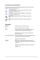
Conventions used in this guide To make sure that you perform certain tasks properly, take note of the following symbols used throughout this manual. DANGER/WARNING: Information to prevent injury to yourself when trying to complete a task. CAUTION: Information to prevent damage to the components when trying to complete a task. IMPORTANT: Instructions that you MUST follow to complete a task. NOTE: Tips and additional information to help you complete a task.
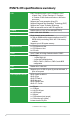
P5N73-CM specifications summary CPU LGA775 socket for Intel® Core™ 2 Extreme / Core™ 2 Quad / Core™ 2 Duo / Pentium® D / Pentium® 4 / Celeron® E1000 Series and Celeron® 400 Series processors Supports Intel® next generation 45nm CPU Supports Enhanced Intel SpeedStep® Technology (EIST) Supports Intel® Hyper-Threading Technology *Refer to www.asus.
P5N73-CM specifications summary Internal connectors 1 x CD audio in connector 1 x 24-pin EPS 12V power connector 1 x 4-pin ATX 12 V power connector 3 x USB connectors for additional six USB 2.
xii
This chapter describes the motherboard features and the new technologies it supports.
1.1 Welcome! Thank you for buying an ASUS® P5N73-CM motherboard! The motherboard delivers a host of new features and latest technologies, making it another standout in the long line of ASUS quality motherboards! P5N73-CM with NVIDIA GeForce 7100 / nForce 630i chipset inside supports Intel® 45nm multi-core CPU and features 1333MHz FSB, PCI Express X 16, Serial ATA interfacee, high performance integrated graphics engine, DDR 2 1066(OC) memory, and HD Audio CODEC.
LGA775 Intel® Quad-core Processor Ready This motherboard supports the latest Intel® Quad-core processors in LGA775 package. It also can support Intel® next generation 45nm Multi-Core CPU. It´s excellent for multi-tasking, multi-media and enthusiastic gamers with 1333/1066/800 MHz FSB. . Intel® Core™2 Processor Ready This motherboard supports the latest Intel® Core™2 processor in the LGA775 package.
Japan-made 5000hrs VRM Solid Capacitors Stable system operation depends upon the quality of CPU VRM (voltage regulator module). ASUS adopts Japan-made 5000hrs Conductive Polymer Solid Capacitors CPU VRM to ensure a longer lifespan for systems in daily operation and boost system stability under extreme conditions. CPU VRM with Polymer Capacitors featuring better electronic conductivity, excellent heat resistance enhances system durability even operating in high temperature environment.
Dual VGA Output This motherboard supports Dual-VGA output (RGB / DVI). DVI interface is compliant with HDCP. 1.3.2 ASUS Special features ASUS Q-Fan technology The ASUS Q-Fan technology smartly adjusts the fan speeds according to the system loading to ensure quiet, cool, and efficient operation. See page 2‑34 for details. ASUS MyLogo2™ This feature allows you to convert your favorite photo into a 256-color boot logo for a more colorful and vivid image on your screen. See page 2-38 for details.
ASUS O.C. Profile The motherboard features the ASUS O.C. Profile that allows users to conveniently store or load multiple BIOS settings. The BIOS settings can be stored in the CMOS or a separate file, giving users freedom to share and distribute their favorite overclocking settings. ASUS Express Gate Taking only 5 seconds to go online from bootup, Express Gate is the one-stop gateway to instant fun! It’s a unique motherboard built-in OS.
1.4 Before you proceed Take note of the following precautions before you install motherboard components or change any motherboard settings. • Unplug the power cord from the wall socket before touching any component. • Use a grounded wrist strap or touch a safely grounded object or to a metal object, such as the power supply case, before handling components to avoid damaging them due to static electricity • Hold components by the edges to avoid touching the ICs on them.
1.5 Motherboard overview Before you install the motherboard, study the configuration of your chassis to ensure that the motherboard fits into it. Ensure to unplug the power cord before installing or removing the motherboard. Failure to do so can cause you physical injury and damage motherboard components. 1.5.1 Placement direction When installing the motherboard, ensure that you place it into the chassis in the correct orientation.
1.5.3 Motherboard layout 21.3cm (8.4in) PS/2KBMS T:Mouse B:Keyboard CPU_FAN ATX12V R COM2 PWR_FAN MCP73PV CHA_FAN 24.5cm (9.
1.6 Central Processing Unit (CPU) The motherboard comes with a surface mount LGA775 socket designed for the Core™2 Extreme / Core™2 Quad / Core™2 Duo / Pentium® D / Pentium® 4 and Celeron® E1000 Series and Celeron® 400 Series processors. 1.6.1 • Your boxed Intel® Core™2 Extreme / Core™2 Quad / Core™2 Duo / Pentium® D / Pentium® 4 or Celeron® E1000 Series and Celeron® 400 Series LGA775 processor package should come with installation instructions for the CPU, fan and heatsink assembly.
2. Press the load lever with your thumb (A) and move it to the left (B) until it is released from the retention tab. Retention tab Load lever PnP Cap A B This side of the cam box should face you. To prevent damage to the socket pins, do not remove the PnP cap unless you are installing a CPU. 3. Lift the load lever in the direction of the arrow to a 135º angle. 4. Lift the load plate with your thumb and forefinger to a 100º angle (A), then push the PnP cap from the load plate window to remove (B).
5. Position the CPU over the socket, making sure that the gold triangle is on the bottom‑left corner of the socket. The socket alignment key should fit into the CPU notch. Alignment key Gold triangle mark 6. Close the load plate (A), then push the load lever (B) until it snaps into the retention tab. A B The CPU fits in only one correct orientation.
1.6.2 Installling the CPU heatsink and fan The Intel® Core™ 2 Extreme / Core™ 2 Quad / Core™ 2 Duo / Pentium D / Pentium® 4 / Celeron® E1000 Series and Celeron® 400 Series processor require a specially designed heatsink and fan assembly to ensure optimum thermal condition and performance.
2. 3. Push down two fasteners at a time in a diagonal sequence to secure the heatsink and fan assembly in place. A B B A B A A B When the fan and heatsink assembly is in place, connect the CPU fan cable to the connector on the motherboard labeled CPU_FAN. CPU FAN PWM CPU FAN IN CPU FAN PWR GND R CPU_FAN P5N73-CM P5N73-CM CPU Fan Connector 1-14 • Do not forget to connect the CPU fan connector! Hardware monitoring errors can occur if you fail to plug this connector.
1.6.3 Uninstalling the CPU heatsink and fan To uninstall the CPU heatsink and fan: 1. 2. 3. Disconnect the CPU fan cable from the connector on the motherboard. Rotate each fastener counterclockwise. Pull up two fasteners at a time in a diagonal sequence to disengage the heatsink and fan assembly from the motherboard.
4. Remove the heatsink and fan assembly from the motherboard. 5. Rotate each fastener clockwise to reset the orientation. Narrow end of the groove The narrow end of the groove should point outward after resetting. (The photo shows the groove shaded for emphasis.
1.7 System memory 1.7.1 Overview The motherboard comes with three Double Data Rate 2 (DDR2) Dual Inline Memory Modules (DIMM) sockets. A DDR2 module has the same physical dimensions as a DDR DIMM but has a 240-pin footprint compared to the 184-pin DDR DIMM. DDR2 DIMMs are notched differently to prevent installation on a DDR DIMM socket.
1.7.2 Memory configurations You may install 256 MB, 512 MB, 1 GB and 2 GB unbuffered non-ECC DDR2 DIMMs into the DIMM sockets. • This motherboard only supports single-channel configuration. • Always install DIMMs with the same CAS latency. For optimum compatibility, it is recommended that you obtain memory modules from the same vendor. • When installing total memory of 4GB capacity or more, Windows 32bit operation system may only recognize less than 3GB.
1.7.3 DDR2 Qualified Vendors List The following table lists the memory modules that have been tested and qualified for use with this motherboard. Visit the ASUS website (www.asus.com) for the latest DDR2 DIMM modules for this motherboard. DDR2 533 Qualified Vendors List Size Vendor Part No. CL Chip Brand SS/ DS Chip No.
DDR2 667 Qualified Vendors List Size 1-20 Vendor Part No. CL Chip Brand SS/ DS Chip No.
DDR2 800 Qualified Vendors List Size Vendor Part No. CL Chip Brand SS/ DS Chip No.
DDR2 1066 Qualified Vendors List Size Vendor Part No. CL Chip Brand SS/ DS Chip No. DIMM support 512MB Kingston KHX8500D2/512 N/A Kingston SS Heat-Sink Package • 1G GEIL GB24GB8500C5QC N/A GEIL SS GL2L128M88BA25AB • A* B* SS - Single-sided / DS - Double - sided DIMM support: • A*: Supports one module inserted into any slot as Single-channel memory configuration. • B*: Supports two modules inserted into both slots as Single-channel memory configuration.
1.7.4 Installing a DIMM Unplug the power supply before adding or removing DIMMs or other system components. Failure to do so can cause severe damage to both the motherboard and the components. To install a DIMM: 1. 2. 3. 2 Unlock a DIMM socket by pressing the retaining clips outward. Align a DIMM on the socket such that the notch on the DIMM matches the break on the socket.
1.8 Expansion slots In the future, you may need to install expansion cards. The following sub‑sections describe the slots and the expansion cards that they support. Ensure to unplug the power cord before adding or removing expansion cards. Failure to do so may cause you physical injury and damage motherboard components. 1.8.1 Installing an expansion card To install an expansion card: 1. 2. 3. 4. 5. 6.
1.8.
IRQ assignments for this motherboard External devices interrupt PIRQ1 PIRQ2 PIRQ3 PIRQ4 PIRQ5 PIRQ6 PIRQ7 PIRQ8 PCI slot 1 shared — — — — — — — PCI slot 2 — shared — — — — — — Onboard USB controller — — — — — — — — Onboard USB 2.
1.8.4 PCI slots The PCI slots support cards such as a LAN card, SCSI card, USB card, and other cards that comply with PCI specifications. The figure shows a LAN card installed on a PCI slot. If you install a PCI graphics card, we recommend that you remove the onboard graphics card driver. 1.8.5 PCI Express x1 slot This motherboard supports PCI Express x1 network cards, SCSI cards and other cards that comply with the PCI Express specifications.
1.9 1. Jumpers Clear RTC RAM (CLRTC) This jumper allows you to clear the Real Time Clock (RTC) RAM in CMOS. You can clear the CMOS memory of date, time, and system setup parameters by erasing the CMOS RTC RAM data. The onboard button cell battery powers the RAM data in CMOS, which include system setup information such as system passwords. To erase the RTC RAM: 1. Turn OFF the computer and unplug the power cord. 3. Move the jumper cap from pins 1-2 (default) to pins 2-3.
1.10 Connectors 1.10.1 Rear panel connectors 2 1 3 45 6 7 8 14 13 12 11 10 9 1. PS/2 mouse port (green). This port is for a PS/2 mouse. 3. LAN (RJ-45) port. Supported by Marvell Gigabit LAN controller, this port allows Gigabit connection to a Local Area Network (LAN) through a network hub. Refer to the table below for the LAN port LED indications. 2. Video Graphics Adapter (VGA) port. This 15-pin port is for a VGA monitor or other VGA-compatible devices.
Refer to the audio configuration table below for the function of the audio ports in 2, 4, 6 or 8-channel configuration. Audio 2, 4, 6, or 8-channel configuration Port Light Blue Lime Pink Orange Black Gray Headset 2-channel Line In Line Out Mic In – – – 4-channel 6-channel 8-channel Line In Front Speaker Out Mic In – Rear Speaker Out – Line In Front Speaker Out Mic In Center/Subwoofer Rear Speaker Out – Line In Front Speaker Out Mic In Center/Subwoofer Rear Speaker Out Side Speaker Out 10. USB 2.
1.10.2 1. Internal connectors Floppy disk drive connector (34-1 pin FLOPPY) This connector is for the provided floppy disk drive (FDD) signal cable. Insert one end of the cable to this connector, then connect the other end to the signal connector at the back of the floppy disk drive. R Pin 5 on the connector is removed to prevent incorrect cable connection when using an FDD cable with a covered Pin 5. FLOPPY P5N73-CM PIN1 NOTE: Orient the red markings on the floppy ribbon cable to PIN 1.
3. IDE connector (40-1 pin PRI_IDE) The onboard IDE connector is for Ultra DMA 133 / 100 / 66 / 33 signal cable. There are three connectors on each Ultra DMA 100/66/33 signal cable: blue, black, and gray. Connect the blue connector to the motherboard’s IDE connector, then select one of the following modes to configure your device(s). R PRI_IDE PIN1 P5N73-CM P5N73-CM IDE Connector NOTE: Orient the red markings (usually zigzag) on the ID ribbon cable to PIN 1.
4. CPU, Chassis, and Power fan connectors (4-pin CPU_FAN, 3-pin CHA_FAN, 3-pin PWR_FAN) The fan connectors support cooling fans of a total of 1A~2.2A (26.4W max.) at +12V. Connect the fan cables to the fan connectors on the motherboard, making sure that the black wire of each cable matches the ground pin of the connector. Do not forget to connect the fan cables to the fan connectors. Insufficient air flow inside the system may damage the motherboard components.
6. ATX power connectors (24-pin EATXPWR and 4-pin ATX12V) These connectors are for ATX power supply plugs. The power supply plugs are designed to fit these connectors in only one orientation. Find the proper orientation and push down firmly until the connectors completely fit. • Do not forget to connect the 4-pin ATX +12 V power plug; otherwise, the system will not boot. • Use of a PSU with a higher power output is recommended when configuring a system with more power-consuming devices.
Optical drive audio connector (4-pin CD) This connector allows you to receive stereo audio input from sound sources such as a CD-ROM, TV tuner, or MPEG card. CD (black) R 7. Right Audio Channel Ground Ground Left Audio Channel P5N73-CM P5N73-CM Internal Audio Connector Enable the CD-IN function in the audio utility when using this connector. USB connectors (10-1 pin USB56, USB78, USB910) These connectors are for USB 2.0 ports.
Front panel audio connector (10-1 pin AAFP) This connector is for a chassis-mounted front panel audio I/O module that supports either HD Audio or legacy AC’97 audio standard. NC Legacy AC’97-compliant pin definition HP_HD AGND PRESENSE# MIC2_JD Azalia-compliant pin definition AGND NC NC R AAFP MIC2_L MIC2_R HP_R Jack_Sense HP_L P5N73-CM MIC2_L MIC2_R Line out_R NC Line out_L 9.
LPT connector (26-1 pin LPT) The LPT (Line Printing Terminal) connector supports devices such as a printer. LPT standardizes as IEEE 1394, which is the parallel port interface on IBM PC-compatible computers. R 11.
12. System panel connector (20-8 pin F_PANEL) This connector supports several chassis-mounted functions. R PANEL PLED 1-38 Ground Reset P5N73-CM System Panel Connector Ground PWR IDE_LEDIDE_LED+ +IDE_LED Speaker Ground Ground +5V PLED- PLED+ P5N73-CM SPEAKER Reset PWRSW • System power LED (2-pin PLED) This 2-pin connector is for the system power LED. Connect the chassis power LED cable to this connector.
This chapter tells how to change the system settings through the BIOS Setup menus. Detailed descriptions of the BIOS parameters are also provided.
2.1 Managing and updating your BIOS The following utilities allow you to manage and update the motherboard Basic Input/Output System (BIOS) setup. 1. ASUS Update: Updates the BIOS in Windows® environment. 3. AwardBIOS Flash Utility: Updates the BIOS in DOS mode using a bootable floppy disk. ASUS EZ Flash 2: Updates the BIOS using a floppy disk/ USB flash disk or the motherboard support DVD. 2.
Quit all Windows® applications before you update the BIOS using this utility. Updating the BIOS through the Internet To update the BIOS through the Internet: 1. Launch the ASUS Update utility from the Windows® desktop by clicking Start > Programs > ASUS > ASUSUpdate > ASUSUpdate. The ASUS Update main window appears. 2. Select Update BIOS from the Internet option from the drop‑down menu, then click Next. ASUS P5N73-CM 3.
4. 5. From the FTP site, select the BIOS version that you wish to download. Click Next. Follow the screen instructions to complete the update process. The ASUS Update utility is capable of updating itself through the Internet. Always update the utility to avail all its features. Updating the BIOS through a BIOS file To update the BIOS through a BIOS file: 1. 2. 3. 4. Launch the ASUS Update utility from the Windows® desktop by clicking Start > Programs > ASUS > ASUSUpdate > ASUSUpdate.
2.1.2 1. Creating a bootable floppy disk Do either one of the following to create a bootable floppy disk. DOS environment a. Insert a 1.44MB floppy disk into the drive. b. At the DOS prompt, type format A:/S then press . Windows® XP environment a. Insert a 1.44 MB floppy disk to the floppy disk drive. b. Click Start from the Windows® desktop, then select My Computer. c. Select the 3 1/2 Floppy Drive icon. d. Click File from the menu, then select Format.
2.1.3 ASUS EZ Flash 2 utility The ASUS EZ Flash 2 feature allows you to update the BIOS without having to go through the long process of booting from a floppy disk and using a DOS‑based utility. The EZ Flash 2 utility is built-in the BIOS chip so it is accessible by pressing + during the Power-On Self Tests (POST). To update the BIOS using EZ Flash 2: 1. 2. 3. Visit the ASUS website (www.asus.com) to download the latest BIOS file for the motherboard.
2.1.4 Updating the BIOS The Basic Input/Output System (BIOS) can be updated using the AwardBIOS Flash Utility. Follow these instructions to update the BIOS using this utility. 1. Download the latest BIOS file from the ASUS web site. Rename the file to P5N73CM.BIN and save it to a floppy disk, CD ROM or a USB flash disk in FAT 16/12 format. Save only the updated BIOS file in the floppy disk to avoid loading the wrong BIOS file. 2. 3. 4. 5. Copy the AwardBIOS Flash Utility (awdflash.
7. 8. Press when the utility prompts you to save the current BIOS file. The following screen appears. The utility verifies the BIOS file in the floppy disk, CD ROM or a USB flash disk and starts flashing the BIOS file. AwardBIOS Flash Utility for ASUS V1.17 (C) Phoenix Technologies Ltd. All Rights Reserved For 690G-SB600-P5N73-CM_H-00 DATE: 12/12/2006 Flash Type - Winbond W39V080A (8Mb) File Name to Program: P5N-EM HDMI.
2.1.5 Saving the current BIOS file You can use the AwardBIOS Flash Utility to save the current BIOS file. You can load the current BIOS file when the BIOS file gets corrupted during the flashing process. Ensure that the floppy disk, CD ROM or a USB flash disk has enough disk space to save the file. To save the current BIOS file using the AwardBIOS Flash Utility: 1. 2. Follow steps 1 to 6 of the previous section. Press when the utility prompts you to save the current BIOS file.
2.1.6 ASUS CrashFree BIOS 2 utility The ASUS CrashFree BIOS 2 is an auto recovery tool that allows you to restore the BIOS file when it fails or gets corrupted during the updating process. You can update a corrupted BIOS file using the motherboard support DVD or the floppy disk that contains the updated BIOS file. • Prepare the motherboard support DVD, or the floppy disk containing the updated motherboard BIOS before using this utility.
Recovering the BIOS from the support DVD To recover the BIOS from the support DVD: 1. Remove any floppy disk from the floppy disk drive, then turn on the system. 3. The utility displays the following message and automatically checks the floppy disk for the original or updated BIOS file. 2. Insert the support DVD to the optical drive. Bad BIOS checksum. Starting BIOS recovery... Checking for floppy...
2.2 BIOS setup program This motherboard supports a programmable Serial Peripheral Interface (SPI) chip that you can update using the provided utility described in section “2.1 Managing and updating your BIOS”. Use the BIOS Setup program when you are installing a motherboard, reconfiguring your system, or prompted to “Run Setup”. This section explains how to configure your system using this utility.
2.2.1 BIOS menu screen Menu items Main Menu bar Configuration fields Phoenix-AwardBIOS CMOS Setup Utility Power Boot Tools Exit Advanced System Time System Date 0 : 7 : 28 Tue, Jan 1 2008 Legacy Diskette A: [1.44M, 3.5 in.
2.2.3 Legend bar At the bottom of the Setup screen is a legend bar. The keys in the legend bar allow you to navigate through the various setup menus. The following table lists the keys found in the legend bar with their corresponding functions.
2.2.7 Pop-up window Select a menu item then press to display a pop-up window with the configuration options for that item. Main Advanced Phoenix-Award BIOS CMOS Setup Utility Power Boot Tools Exit System Time System Date 0 : 14 : 36 Tue, Jan 1 2008 Legacy Diskette A: [1.44M, 3.5 in.] Primary IDE MasterLegacy Diskette [ST321122A] A: Primary IDE Slave [ASUS CDS520/A] SATA1 [None] Disabled ..... [ ] SATA2 [None] 720K , 3.5 in. ..... [ ] SATA3 [None] 1.44M, 3.5 in. .....
2.3 Main menu When you enter the BIOS Setup program, the Main menu screen appears, giving you an overview of the basic system information. Refer to section “2.2.1 BIOS menu screen” for information on the menu screen items and how to navigate through them.
2.3.4 Primary IDE Master/Slave While entering Setup, the BIOS automatically detects the presence of IDE devices. There is a separate sub-menu for each IDE device. Select a device item then press to display the IDE device information.
Before attempting to configure a hard disk drive, ensure that you have the correct configuration information supplied by the drive manufacturer. Incorrect settings may cause the system to fail to recognize the installed hard disk. Capacity Displays the auto-detected hard disk capacity. This item is not configurable. Cylinder Shows the number of the hard disk cylinders. This item is not configurable. Head Shows the number of the hard disk read/write heads. This item is not configurable.
2.3.5 SATA 1-4 While entering Setup, the BIOS automatically detects the presence of Serial ATA devices. There is a separate sub-menu for each SATA device. Select a device item then press to display the SATA device information.
Landing Zone Shows the number of landing zone per track. This item is not configurable. Sector Shows the number of sectors per track. This item is not configurable. After entering the IDE hard disk drive information into BIOS, use a disk utility, such as FDISK, to partition and format new IDE hard disk drives. This is necessary so that you can write or read data from the hard disk. Ensure to set the partition of the Primary IDE hard disk drives to active. 2.3.
2.4 Advanced menu The Advanced menu items allow you to change the settings for the CPU and other system devices. Take caution when changing the settings of the Advanced menu items. Incorrect field values can cause the system to malfunction. Main Advanced Power Phoenix-Award BIOS CMOS Setup Utility Boot Tools Exit Select Menu Jumperfree AI NET 2 Item Specific Help CPU Configuration Chipset PCIPnP Onboard Device Configuration USB Configuration F1:Help ESC: Exit 2.4.
FSB (QDR), MHz [Auto] Allows you to adjust CPU FSB frequency from 600 to 2000. You may enter a new value or use +/- keys to adjust. This item becomes user-configurabled when the FSB - Memory Clock Mode item is set to [Linked] or [Unlinked]. The Actual FSB (QDR) reflects the actual frequency that takes effect on a reboot. MEM (DDR), MHz [Auto] Allows you to adjust the memory frequency from 400 to 1400. You may enter a new value or use +/- keys to adjust.
tRCD [Auto] Allows you to set RAS to CAS delay for a RD/WR command to the same bank. Configuration options: [Auto] [1] [2] [3] [4] [5] [6] [7] tRP [Auto] Allows you to set the row precharge time Precharge-to-Active or AutoRefresh of the same bank. Configuration options: [Auto] [1] [2] [3] [4] [5] [6] [7] tRAS [Auto] Allows you set the minimum RAS active time. Configuration options: [Auto] [1] [2] [3] [4] [5] [6] [7]...[31] Command Per Clock (CMD) [Auto] Allows you to command timing setting (per clock unit).
2.4.2 AI NET 2 Check Realtek Phy LAN cable during POST. AI NET 2 Post Check LAN cable [Disabled] Pair LAN1(1-2) LAN1(3-6) LAN1(4-5) LAN1(7-8) Status Open Open Open Open Length N/A N/A N/A N/A +- F1 F10 ESC Select Screen Select Item Change Option General Help Save and Exit Exit Post check LAN cable [Disabled] Enables or disables checking of the post LAN cable.
2.4.3 CPU Configuration Advanced Phoenix-Award BIOS CMOS Setup Utility CPU Configuration Inter(R) Core(TM)2 CPU 6300 @ 1.86GHz CPU Speed 1.86GHz Cache RAM 2048K [Auto] CPU Internal Thermal Control Limit CPUID MaxVal [Disabled] Enhanced C1 (C1E) [Disabled] Execute Disable Bit [Enabled] Virtualization Technology [Enabled] CPU Multiplier [ 7.0] Enhanced Intel SpeedStep(tm) Tech.
2.4.
2.4.6 Onboard Device Configuration Phoenix-Award BIOS CMOS Setup Utility Advanced Onboard Device Configuration x IDE Function Setup Serial-ATA configuration HD Audio Controller Front Panel Support Type Onboard nVidia LAN Onboard LAN Boot ROM Serial Port1 Address Parallel Port Address Parallel Port Mode EPP Mode Select ECP Mode Use DMA F1:Help ESC: Exit ↑↓ : Select Item →←: Select Menu Select Menu Item Specific Help [Auto] [HD Audio] [Enabled] [Disabled] [3F8/IRQ4] [378/IRQ7] [ECP] EPP1.
Serial-ATA configuration Advanced Phoenix-Award BIOS CMOS Setup Utility Serial-ATA configuration X X X X SATA SATA SATA SATA SATA Operation Mode 1 2 3 4 [IDE] Disabled Disabled Disabled Disabled Select Menu Item Specific Help SATA Operation Mode [IDE] Allows you to select SATA operation mode. Configuration options: [IDE] [RAID] [AHCI]. The following items become user-configurable when the SATA Operation Mode item is set to [RAID].
Serial Port1 Address [3F8/IRQ4] Allows you to select the Serial Port1 base address. Configuration options: [Disabled] [3F8/IRQ4] [2F8/IRQ3] [3E8/IRQ4] [2E8/IRQ3] [Auto] Parallel Port Address [378/IRQ7] Allows you to select the Parallel Port address. Configuration options: [Disabled] [378/IRQ7] [278/IRQ5] [3BC/IRQ7] Parallel Port Mode [ECP] Allows you to select the Parallel Port mode.
2.4.7 USB Configuration The items in this menu allows you to change the USB-related features. Select an item then press to display the configuration options. Phoenix-Award BIOS CMOS Setup Utility Advanced USB Configuration USB Controller USB 2.0 Controller USB Legacy support [Enabled] [Enabled] [Enabled] Select Menu Item Specific Help Enable or Disable USB 1.1 and 2.0 Controller USB Controller [Enabled] Allows you to enable or disable the USB controller.
2.5 Power menu The Power menu items allow you to change the settings for the Advanced Configuration and Power Interface (ACPI) and the Advanced Power Management (APM). Select an item then press to display the configuration options. Main Advanced Phoenix-Award BIOS CMOS Setup Utility Power Boot Tools Exit ACPI Suspend Type ACPI APIC support APM Configuration HardWare Monitor Item Specific Help Select the ACPI state used for System Suspend.
Restore on AC Power Loss [Power Off] When set to Power Off, the system goes into off state after an AC power loss. When set to Power On, the system goes on after an AC power loss. When set to Configuration options: [Power Off] [Power On] [Last State] PWR Button < 4 secs [Instant-Off] Allows you to set the event after the power button is pressed for more than 4 seconds.
Alarm Time (hh:mm) [0:0:0] To set the time of alarm: 1. Highlight this item and press to display a pop-up menu for the hour field. 2. Key-in a value (Min=0, Max=23), then press . 3. Press to move to the minutes field then press . 4. Key-in a minute value (Min=0, Max=59), then press . 5. Press to move to the seconds field then press . 6. Key-in a value (Min=0, Max=59), then press .
2.5.4 Hardware Monitor The items in this sub-menu displays the hardware monitor values automatically detected by the BIOS. It also allows you to change CPU Q-Fan feature-related parameters. Select an item then press to display the configuration options.
Vcore, Vcc 12, Vcc 3.3V, 5V The onboard hardware monitor automatically detects the voltage output through the onboard voltage regulators. Configuration options: [xxx] [Ignored] CPU Fan Speed warning [600 RPM] Sets the CPU fan speed warning feature.
2.6 Boot menu The Boot menu items allow you to change the system boot options. Select an item then press to display the sub-menu. Phoenix-Award BIOS CMOS Setup Utility Main Advanced Power Boot Tools Exit Select Menu Boot Device Priority Removable Drives Boot Settings Configuration Security Item Specific Help Select Boot Device Priority F1:Help ESC: Exit 2.6.
2.6.3 Boot Settings Configuration Phoenix-Award BIOS CMOS Setup Utility Boot Boot Settings Configuration x x Quick Boot Boot Up Floppy Seek Bootup Num-Lock Typematic Rate Setting Typematic Rate (Chars/Sec) Typematic Delay (Msec) Full Screen LOGO Halt On F1:Help ESC: Exit ↑↓ : Select Item →←: Select Menu [Enabled] [Disabled] [On] [Disabled] 6 250 [Enabled] [All Errors] -/+: Change Value Enter: Select SubMenu Select Menu Item Specific Help Allows the system to skip certain tests while booting.
Typematic Rate (Chars/Sec) [6] Allows you to select the rate at which a character repeats when you hold a key. Configuration options: [6] [8] [10] [12] [15] [20] [24] [30] Typematic Delay (Msec) [250] Allows you to set the delay before keystrokes begin to repeat. Configuration options: [250] [500] [750] [1000] Full Screen LOGO [Enabled] Allows you to enable or disable the full screen logo display feature.
2.6.4 Security Phoenix-Award BIOS CMOS Setup Utility Boot Select Menu Security Supervisor Password User Password Password Check Clear Clear [Setup] Item Specific Help Supervisor Password User Password These fields allow you to set passwords: To set a password: 1. 2. 3. Select an item then press . Type in a password using a combination of a maximum of eight (8) alphanumeric characters, then press .
2.7 Tools menu The Tools menu items allow you to configure options for special functions. Select an item then press to display the sub-menu. Main Advanced Power Phoenix-Award BIOS CMOS Setup Utility Boot Tools Exit ASUS EZ Flash 2 Express Gate Select Menu Item Specific Help Press [Enter] to Run ASUS EX Flash 2 F1:Help ESC: Exit 2.7.
2.7.2 Express Gate [Enabled] Allows you to enable or disable the ASUS Express Gate feature. The ASUS Express Gate feature is a unique instant-on environment that provides quick access to the Internet browser and Skype. Configuration options: [Enabled] [Disabled] Enter OS Timer [10 Seconds] Sets countdown duration that the system waits at the Express Gate’s first screen before starting Windows or other installed OS. Choose [Prompt User] to stay at the first screen of Express Gate for user action.
2.8 Exit menu The Exit menu items allow you to load the optimal or failsafe default values for the BIOS items, and save or discard your changes to the BIOS items.
This chapter describes the contents of the support DVD that comes with the motherboard package.
3.1 Installing an operating system This motherboard supports Windows® 32-bit XP / 32-bit Vista / 64-bit XP / 64bit Vista Operating Systems (OS). Always install the latest OS version and corresponding updates to maximize the features of your hardware. 3.2 • Motherboard settings and hardware options vary. Use the setup procedures presented in this chapter for reference only. Refer to your OS documentation for detailed information.
3.2.2 Drivers menu The drivers menu shows the available device drivers if the system detects installed devices. Install the necessary drivers to activate the devices. ASUS InstAll - Installation Wizard for Anti-Virus and Drivers Utility Launches the ASUS InstallAll driver installation wizard. Norton Internet Security 2008 Installs the Norton Internet Security 2008. Nvidia nForce Chipset Driver Installs the Nvidia chipset driver. VIA Audio Driver Installs the VIA audio driver.
3.2.3 Utilities menu The Utilities menu shows the applications and other software that the motherboard supports. ASUS InstAll - Installation Wizard for Utilities Install all of the utilities through the Installation Wizard. ASUS PC Probe II This smart utility monitors the fan speed, CPU temperature, and system voltages, and alerts you of any detected problems. This utility helps you keep your computer in healthy operating condition.
Corel MediaOne Starter Installs the Corel MediaOne Starter application to easily manage, edit share and protect your multimedia data. CyberLink PowerBackup Installs CyberLink PowerBackup to back up and restore your data easily. WinZip 11 Installs the Winzip utility for easy file-compression and protection. Ulead Burn. Now Installs the Ulead Burn. Now application for Audio DVD,CD and data disc creation. Ulead Photolmpact 12 SE Installs the Photolmpact image editing software.
3.2.4 Make Disk menu The Make Disk menu allows you to make a RAID driver disk. NVIDIA 32/64 bit Vista AHCI Driver Allows you to create the NVIDIA® 32/64-bit Vista AHCI disk. NVIDIA 32 bit XP AHCI Driver [Disk1] Allows you to create the NVIDIA® 32-bit XP AHCI disk1. NVIDIA 32 bit XP AHCI Driver [Disk2] Allows you to create the NVIDIA® 32-bit XP AHCI disk2. NVIDIA 64 bit XP AHCI Driver [Disk1] Allows you to create the NVIDIA® 64-bit XP AHCI disk1.
NVIDIA 64 bit XP SATA RAID Driver [Disk1] Allows you to create the NVIDIA® 64-bit XP SATA RAID disk1. NVIDIA 64 bit XP SATA RAID Driver [Disk2] Allows you to create the NVIDIA® 64-bit XP SATA RAID disk2.
3.2.5 Manual menu The Manual menu contains a list of supplementary user manuals. Click an item to open the folder of the user manual. Most user manual files are in Portable Document Format (PDF). Install the Adobe® Acrobat® Reader from the Utilities menu before opening a user manual file. NVIDIA® SATA RAID User’s Manual Allows you to open the NVIDIA® SATA RAID user’s manual. ASUS Motherboard Installation Guide Allows you to open ASUS motherboard installation guide.
3.2.6 ASUS Contact information Click the Contact tab to display the ASUS contact information. You can also find this information on the inside front cover of this user guide. 3.2.7 Other information The icons on the top right corner of the screen give additional information on the motherboard and the contents of the support DVD. Click an icon to display the specified information. Motherboard Info Displays the general specifications of the motherboard.
Browse this DVD Displays the support DVD contents in graphical format. Technical Support Form Displays the ASUS Technical Support Request Form that you have to fill out when requesting technical support. Filelist Displays the contents of the support DVD and a brief description of each in text format.
3.3 Creating a RAID driver disk A floppy disk with the RAID driver is required when installing Windows® 32-bit XP / 32-bit Vista / 64-bit XP / 64-bit Vista OS on a hard disk drive that is included in a RAID set. To create a RAID driver disk: 1. Place the motherboard support DVD into the DVD-ROM drive. 3. From the Make Disk menu, select the RAID driver disk you want to create or browse the contents of the support DVD to locate the driver disk utility. 2. Select Make Disk tab.
3-12 Chapter 3: Software support
The Appendix describes the CPU features that the motherboard supports.
A.1 A.1.1 Enhanced Intel SpeedStep® Technology (EIST) • The motherboard comes with a BIOS file that supports EIST. You can download the latest BIOS file from the ASUS website (www.asus.com/ support/download/) if you need to update the BIOS. See Chapter 2 for details. • Visit www.intel.com for more information on the EIST feature.
8. 9. On the Power schemes section, click , then select any option except Home/Office Desktop or Always On. Click Apply, then click OK. 10. Close the Display Properties window. After you adjust the power scheme, the CPU internal frequency slightly decreases when the CPU loading is low. The screen displays and procedures may vary depending on the operating system.
A.2 Intel® Hyper-Threading Technology • The motherboard supports Intel® Pentium® 4 LGA775 processors with Hyper-Threading Technology. • Hyper-Threading Technology is supported under Windows® XP and Linux 2.4.x (kernel) and later versions only. Under Linux, use the HyperThreading compiler to compile the code. If you are using any other operating systems, disable the Hyper-Threading Techonology item in the BIOS to ensure system stability and performance.