Motherboard P5P43TD
E4782 First Edition V1 Jun 2009 Copyright © 2009 ASUSTeK Computer Inc. All Rights Reserved. No part of this manual, including the products and software described in it, may be reproduced, transmitted, transcribed, stored in a retrieval system, or translated into any language in any form or by any means, except documentation kept by the purchaser for backup purposes, without the express written permission of ASUSTeK Computer Inc. (“ASUS”).
Contents Notices.......................................................................................................... vi Safety information...................................................................................... vii About this guide......................................................................................... vii P5P43TD specifications summary............................................................. ix Chapter 1: Product introduction 1.1 Welcome!........................
Contents 1.10 1.11 Connectors.................................................................................. 1-21 1.10.1 1.10.2 1.11.1 Chapter 2: 2.1.3 ASUS CrashFree BIOS 3 utility....................................... 2-3 2.2.1 BIOS menu screen........................................................... 2-5 2.2.3 Navigation keys................................................................ 2-6 2.2.6 2.2.7 2.2.8 2.2.9 Menu bar.................................................................
Contents 2.6 Power menu................................................................................. 2-18 2.6.1 Suspend Mode............................................................... 2-18 2.6.3 ACPI APIC Support........................................................ 2-18 2.6.2 2.6.4 2.7 2.6.5 Hardware Monitor.......................................................... 2-19 2.7.1 Boot Device Priority....................................................... 2-20 2.7.3 Security................
Notices Federal Communications Commission Statement This device complies with Part 15 of the FCC Rules. Operation is subject to the following two conditions: • • This device may not cause harmful interference, and This device must accept any interference received including interference that may cause undesired operation. This equipment has been tested and found to comply with the limits for a Class B digital device, pursuant to Part 15 of the FCC Rules.
Safety information Electrical safety • • • • • • To prevent electrical shock hazard, disconnect the power cable from the electrical outlet before relocating the system. When adding or removing devices to or from the system, ensure that the power cables for the devices are unplugged before the signal cables are connected. If possible, disconnect all power cables from the existing system before you add a device.
Where to find more information Refer to the following sources for additional information and for product and software updates. 1. ASUS websites 2. The ASUS website provides updated information on ASUS hardware and software products. Refer to the ASUS contact information. Optional documentation Your product package may include optional documentation, such as warranty flyers, that may have been added by your dealer. These documents are not part of the standard package.
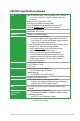
P5P43TD specifications summary CPU Chipset System bus Memory Expansion slots Storage LAN Audio USB ASUS exclusive overclocking features LGA775 Socket for Intel® Core™2 Extreme / Core™2 Quad / Core™2 Duo / Pentium® dual-core / Celeron® dual-core processors Supports Intel® 45nm multi-core CPU Intel® Hyper-Threading Technology ready Support Enhanced Intel SpeedStep Technology (EIST) * Refer to www.asus.com for Intel® CPU support list. Northbridge: Intel® P43 Southbridge: Intel® ICH10 1600(O.
P5P43TD specifications summary ASUS Special features Rear panel ports Internal connectors BIOS features Manageability Accessories Support DVD Form factor ASUS CrashFree BIOS 3 ASUS EZ Flash 2 ASUS EPU-4 Engine ASUS Q-Fan ASUS Turbo Key ASUS AI NET 2 ASUS MyLogo 2 ASUS Express Gate 1 x PS/2 Keyboard / Mouse Combo port 1 x COM port 1 x LPT port 1 x Optical S/PDIF out port 1 x LAN (RJ-45) port 6 x USB 2.0/1.1 ports 8-channel audio I/O ports 3 x USB 2.0/1.1 connectors support additional 6 USB 2.0/1.
Chapter 1 Product introduction 1.1 Welcome! Thank you for buying an ASUS® P5P43TD motherboard! The motherboard delivers a host of new features and latest technologies, making it another standout in the long line of ASUS quality motherboards! Before you start installing the motherboard, and hardware devices on it, check the items in your package with the list below. 1.2 Package contents Check your motherboard package for the following items.
Dual channel DDR3 1600 (O.C.)/1333/1066/800 support This motherboard supports DDR3 memory that features data transfer rates of 1600 (O.C.)/1333/1066/800 MHz providing great performance for 3D graphics and other memory-demanding applications. PCI Express architecture PCI Express is the latest I/O interconnect technology that replaces the existing PCI. With a bus bandwidth two times higher than that of AGP 8X interface, PCI Express x16 bus performs much better in applications such as 3D gaming.
ASUS EZ Flash 2 ASUS EZ Flash 2 is a utility that allows you to update the BIOS without using an OS-based utility. ASUS EPU The ASUS EPU (Energy Processing Unit) provides total system power management by detecting current PC loading and intelligently moderating power in real-time. It automatically provides the most appropriate power usage to save power and money! Express Gate Express Gate is a unique OS built into the motheroard.
1.4 Before you proceed Take note of the following precautions before you install motherboard components or change any motherboard settings. • Unplug the power cord from the wall socket before touching any component. • Before handling components, use a grounded wrist strap or touch a safely grounded object or a metal object, such as the power supply case, to avoid damaging them due to static electricity. • Hold components by the edges to avoid touching the ICs on them.
1.5 Motherboard overview Before you install the motherboard, study the configuration of your chassis to ensure that the motherboard fits into it. Ensure that you unplug the power cord before installing or removing the motherboard. Failure to do so can cause you physical injury and damage motherboard components. 1.5.1 Placement direction 1.5.2 Screw holes When installing the motherboard, ensure that you place it into the chassis in the correct orientation.
1-6 1.5.3 Motherboard layout 1.5.4 Layout contents Connectors/Jumpers/Slots/LED Page Connectors/Jumpers/Slots/LED Page 1. ATX power connectors (24-pin EATXPWR, 4-pin ATX12V) 1-23 8. USB connectors (10-1 pin USB78, USB910, USB1112) 1-27 2. CPU and chassis fan connectors (4-pin CPU_FAN, 1-22 3-pin CHA_FAN1) 9. System panel connector (20-8 pin PANEL) 1-26 3. LGA775 CPU socket 1-7 10. Digital audio connector (4-1 pin SPDIF_OUT) 1-23 4. DDR3 DIMM slots 1-12 11.
1.6 Central Processing Unit (CPU) The motherboard comes with a surface mount LGA775 socket designed for the Intel® Core™2 Extreme / Core™2 Quad / Core™2 Duo / Pentium® dual-core /Celeron® dual-core processors. • Unplug all power cables before installing the CPU. • Connect the chassis fan cable to the CHA_FAN connector to ensure system stability. • Upon purchase of the motherboard, ensure that the PnP cap is on the socket and the socket contacts are not bent.
2. Press the load lever with your thumb (A), then move it to the left (B) until it is released from the retention tab. To prevent damage to the socket pins, do not remove the PnP cap unless you are installing a CPU. Retention tab A B Load lever 3. 4. Lift the load lever in the direction of the arrow to a 135º angle. PnP cap Load plate 4B Lift the load plate with your thumb and forefinger to a 100º angle (4A), then push the PnP cap from the load plate window to remove (4B). 4A 3 5.
6. Apply some Thermal Interface Material to the exposed area of the CPU that the heatsink will be in contact with, ensuring that it is spread in an even thin layer. Some heatsinks come with pre-applied thermal paste. If so, skip this step. DO NOT eat the Thermal Interface Material. If it gets into your eyes or touches your skin, ensure that you wash it off immediately, and seek professional medical help. To prevent contaminating the paste, DO NOT spread the paste with your finger directly. 7.
1.6.2 Installing the CPU heatsink and fan The Intel® LGA775 processor requires a specially designed heatsink and fan assembly to ensure optimum thermal condition and performance. • When you buy a boxed Intel® processor, the package includes the CPU fan and heatsink assembly. If you buy a CPU separately, ensure that you use only Intel®‑certified multi‑directional heatsink and fan. • Your Intel® LGA775 heatsink and fan assembly comes in a push-pin design and requires no tool to install.
3. Connect the CPU fan cable to the connector on the motherboard labeled CPU_FAN. Do not forget to connect the CPU fan connector! Hardware monitoring errors can occur if you fail to plug this connector. 1.6.3 Uninstalling the CPU heatsink and fan To uninstall the CPU heatsink and fan: 1. Disconnect the CPU fan cable from the connector on the motherboard. 2. Rotate each fastener counterclockwise. 3.
4. Carefully remove the heatsink and fan assembly from the motherboard. 5. Rotate each fastener clockwise to ensure correct orientation when reinstalling. 1.7 System memory 1.7.1 Overview The motherboard comes with four Double Data Rate 3 (DDR3) Dual Inline Memory Modules (DIMM) sockets.
1.7.2 Memory configurations You may install 512MB, 1GB, 2GB, and 4GB unbuffered non‑ECC DDR3 DIMMs into the DIMM sockets. • You may install varying memory sizes in Channel A and Channel B. The system maps the total size of the lower-sized channel for the dual-channel configuration. Any excess memory from the higher-sized channel is then mapped for single-channel operation.
P5P43TD Motherboard Qualified Vendors Lists (QVL) DDR3-1600 (O.C.) MHz capability 1-14 SS/ DD Chip Brand Chip No. CL DIMM Support Vendor Part No. Size A-DATA AD31600E001GMU 3072MB(Kit of 3) SS N/A Heat-Sink Package 8-8-8-24(1333-9-9-9-24) • A-DATA AD31600F002GMU(XMP) 6144MB(Kit of 3) DS N/A Heat-Sink Package 7-7-7-20(1333-9-9-9-24) • • CORSAIR TR3X3G1600C8D(XMP)Ver2.
DDR3-1333 MHz capability Size SS/DD Chip Brand Chip No. CL DIMM Support Vendor Part No. A* B* A-Data AD31333001GOU 1024MB SS A-Data AD30908C8D-151C E0906 N/A • • A-Data AD31333002GOU 2048MB DS A-Data AD30908C8D-151C E0903 N/A • • Apacer 78.01GC6.9L0 1024MB SS Apacer AM5D5808AEWSBG0914E 9 • • Apacer 78.A1GC6.
DDR3-1333 MHz capability Size SS/DD Chip Brand Chip No. CL DIMM Support Vendor Part No.
SS - Single-sided / DS - Double - sided DIMM support: • A*: Supports one module inserted into any slot as Single-channel memory configuration. • B*: Supports one pair of modules inserted into either the orange or black slots as one pair of Dual-channel memory configuration. • C*: S upports four modules inserted into both the orange and black slots as two pairs of Dual-channel memory configuration. Visit the ASUS website at www.asus.com for the latest QVL. 1.7.
1.7.4 Removing a DIMM To remove a DIMM: 1. Simultaneously press the retaining clips outward to unlock the DIMM. Support the DIMM lightly with your fingers when pressing the retaining clips. The DIMM might get damaged when it flips out with extra force. 2 1 1 DDR3 DIMM notch 2. 1-18 Remove the DIMM from the socket.
1.8 Expansion slots In the future, you may need to install expansion cards. The following sub‑sections describe the slots and the expansion cards that they support. Unplug the power cord before adding or removing expansion cards. Failure to do so may cause you physical injury and damage motherboard components. 1.8.1 Installing an expansion card To install an expansion card: 1.
1.9 1. Jumpers Clear RTC RAM (3-pin CLRTC) This jumper allows you to clear the Real Time Clock (RTC) RAM in CMOS. You can clear the CMOS memory of date, time, and system setup parameters by erasing the CMOS RTC RAM data. The onboard button cell battery powers the RAM data in CMOS, which include system setup information such as system passwords. To erase the RTC RAM: 1. Turn OFF the computer and unplug the power cord. 2. Move the jumper cap from pins 1-2 (default) to pins 2-3.
1.10 Connectors 1.10.1 Rear panel connectors 1. PS/2 Keyboard/Mouse Combo port (purple). This port is for a PS/2 keyboard or mouse. 2. Parallel port. This 25-pin port connects a parallel printer, a scanner, or other devices. 3. LAN (RJ-45) port. This port allows Gigabit connection to a Local Area Network (LAN) through a network hub. Refer to the table below for the LAN port LED indications.
Audio 2, 4, 6, or 8-channel configuration Port Headset 2-channel 4-channel 6-channel 8-channel Lime Line Out Front Speaker Out Front Speaker Out Front Speaker Out Orange - - Center/Subwoofer Center/Subwoofer Black - Rear Speaker Out Rear Speaker Out Rear Speaker Out Gray - - - Side Speaker Out Light Blue Pink Line In Mic In Line in Mic In Line in Mic in Line in Mic in 10. USB 2.0 ports 1 and 2.
2. ATX power connectors (24-pin EATXPWR, 4-pin ATX12V) These connectors are for ATX power supply plugs. The power supply plugs are designed to fit these connectors in only one orientation. Find the proper orientation and push down firmly until the connectors completely fit. • For a fully configured system, we recommend that you use a power supply unit (PSU) that complies with ATX 12 V Specification 2.0 (or later version) and provides a minimum power of 400 W.
4. Serial ATA connectors (7-pin SATA1-6) These connectors are for the Serial ATA signal cables for Serial ATA 3Gb/s hard disk and optical disk drives. The Serial ATA 3Gb/s is backward compatible with Serial ATA 1.5Gb/s specification. The data transfer rate of the Serial ATA 3Gb/s is faster than the standard parallel ATA with 133 MB/s (Ultra DMA133). Install the Windows® XP Service Pack 1 or later version before using Serial ATA. 5.
6. IDE connector (40-1 pin PRI_EIDE) The onboard IDE connector is for the Ultra DMA 133/100/66 signal cable. There are three connectors on each Ultra DMA 133/100/66 signal cable: blue, black, and gray. Connect the blue connector to the motherboard’s IDE connector, then select one of the following modes to configure your device.
7. • • • • • 1-26 System panel connector (20-8 pin PANEL) This connector supports several chassis-mounted functions. System power LED (2-pin PLED) This 2-pin connector is for the system power LED. Connect the chassis power LED cable to this connector. The system power LED lights up when you turn on the system power, and blinks when the system is in sleep mode. Hard disk drive activity LED (2-pin IDE_LED) This 2-pin connector is for the HDD Activity LED.
8. USB connectors (10-1 pin USB78, USB910, USB1112) These connectors are for USB 2.0 ports. Connect the USB module cable to any of these connectors, then install the module to a slot opening at the back of the system chassis. These USB connectors comply with USB 2.0 specification that supports up to 480 Mbps connection speed. Never connect a 1394 cable to the USB connectors. Doing so will damage the motherboard! The USB module cable is purchased separately. 9.
1.11 Software support 1.11.1 Installing an operating system This motherboard supports Windows® XP/Vista Operating Systems (OS). Always install the latest OS version and corresponding updates to maximize the features of your hardware. • Motherboard settings and hardware options vary. Refer to your OS documentation for detailed information.
Chapter 2 BIOS information 2.1 Managing and updating your BIOS Save a copy of the original motherboard BIOS file to a USB flash disk in case you need to restore the BIOS in the future. Copy the original motherboard BIOS using the ASUS Update utility. 2.1.1 ASUS Update utility The ASUS Update is a utility that allows you to manage, save, and update the motherboard BIOS in Windows® environment. • ASUS Update requires an Internet connection either through a network or an Internet Service Provider (ISP).
The ASUS Update utility is capable of updating itself through the Internet. Always update the utility to avail all its features. Updating from a BIOS file 3. a. Select Update BIOS from a file, then click Next. b. Locate the BIOS file from the Open window, then click Open. Follow the onscreen instructions to complete the updating process. 2.1.2 ASUS EZ Flash 2 utility The ASUS EZ Flash 2 feature allows you to update the BIOS without using an OS‑based utility.
• Only a USB flash disk with FAT 32/16 format and single partition can support the ASUS EZ Flash 2 utility. • Do not shut down or reset the system while updating the BIOS to prevent system boot failure! 2.1.3 ASUS CrashFree BIOS 3 utility The ASUS CrashFree BIOS 3 is an auto recovery tool that allows you to restore the BIOS file when it fails or gets corrupted during the updating process.
4. Restart the system after the utility completes the updating process. • Only a USB flash disk with FAT 32/16 format and single partition can support ASUS CrashFree BIOS 3. The device size should be smaller than 8GB. • DO NOT shut down or reset the system while updating the BIOS! Doing so can cause system boot failure! The recovered BIOS may not be the latest BIOS version for this motherboard. Download the latest BIOS file from the ASUS website at www.asus.com. 2.
• The default BIOS settings for this motherboard apply for most conditions to ensure optimum performance. If the system becomes unstable after changing any BIOS settings, load the default settings to ensure system compatibility and stability. Select the Load Setups Defaults item under the Exit Menu. See section 2.9 Exit Menu. • The BIOS setup screens shown in this section are for reference purposes only, and may not exactly match what you see on your screen. • Visit the ASUS website at www.asus.
2.2.3 Navigation keys At the bottom right corner of a menu screen are the navigation keys for that particular menu. Use the navigation keys to select items in the menu and change the settings. Some of the navigation keys differ from one screen to another. 2.2.4 Menu items 2.2.5 Submenu items 2.2.6 Configuration fields 2.2.7 Pop-up window The highlighted item on the menu bar displays the specific items for that menu. For example, selecting Main shows the Main menu items.
2.3 Main menu When you enter the BIOS Setup program, the Main menu screen appears, giving you an overview of the basic system information. Refer to section 2.2.1 BIOS menu screen for information on the menu screen items and how to navigate through them.
LBA/Large Mode [Auto] Enables or disables the LBA mode. Setting to [Auto] enables the LBA mode if the device supports this mode, and if the device was not previously formatted with LBA mode disabled. Configuration options: [Disabled] [Auto] Block (Multi-sector Transfer) M [Auto] Enables or disables data multi-sectors transfers. When set to [Auto], the data transfer from and to the device occurs multiple sectors at a time if the device supports multi-sector transfer feature.
2.3.5 System Information This menu gives you an overview of the general system specifications. The BIOS automatically detects the items in this menu. Bios Information Displays the auto-detected BIOS information. Processor Displays the auto-detected CPU specification. System Memory Displays the auto-detected system memory. 2.4 Ai Tweaker menu The Ai Tweaker menu items allow you to change the settings for the CPU and other system devices.
Ai Overclock Tuner [Auto] Allows selection of CPU overclocking options to achieve desired CPU internal frequency. Select either one of the preset overclocking configuration options: Manual - Allows you to individually set overclocking parameters. Auto - Loads the optimal settings for the system. X.M.P. - If you install memory module(s) supporting the eXtreme Memory Profile X.M.P.) Technology, choose this item to set the profile(s) supported by your memory module(s) for optimizing the system performance.
DRAM CLK Skew on Channel A1/A2/B1/B2 [Auto] Allows you to set the DIMM clock skew on channel A1, A2, B1, and B2. Configuration options: [Auto] [Advance 350ps] [Advance 300ps] [Advance 250ps] [Advance 200ps] [Advance 150ps] [Advance 100ps] [Advance 50ps] [Normal] [Delay 50ps] [Delay 100ps] [Delay 150ps] [Delay 200ps] [Delay 250ps] [Delay300ps] [Delay 350ps] DRAM Timing Control [Auto] Allows you to select the DRAM timing configuration.
2nd Information: 9-4-7-4-9-4-7 READ to WRITE Delay (S/D) [Auto] WRITE to READ Delay (S) [Auto] WRITE to READ Delay (D) [Auto] READ to READ Delay (S) [Auto] READ to READ Delay (D) [Auto] WRITE to WRITE Delay (S) [Auto] WRITE to WRITE Delay (D) [Auto] Configuration options: [Auto] [1 DRAM Clocks] [2 DRAM Clocks] [3 DRAM Clocks] [4 DRAM Clocks] [5 DRAM Clocks] [6 DRAM Clocks] [7 DRAM Clocks] [8 DRAM Clocks] [9 DRAM Clocks] [10 DRAM Clocks] [11 DRAM Clocks] [12 DRAM Clocks] [13 DRAM Clocks] [14 DRAM Clocks] [1
Ai Clock Twister [Auto] Allows you to set the DRAM performance. Configuration options: [Auto] [Lighter] [Light] [Moderate] [Strong] [Stronger] Ai Transaction Booster [Auto] Allows you to set the system performance. Configuration options: [Auto] [Manual] The following items appear only when you set the Ai Transaction Booster item to [Manual]. C/P : A1 A2 LVL : 08 08 Common Performance Level [05] Set this item to a higher level for better compatiility or a lower level for better performance.
2.5 Advanced menu The Advanced menu items allow you to change the settings for the CPU and other system devices. Take caution when changing the settings of the Advanced menu items. Incorrect field values can cause the system to malfunction. Main Ai Tweaker Advanced BIOS SETUP UTILITY Power Boot Tools CPU Configuration Chipset Onboard Devices Configuration USB Configuration PCIPnP 2.5.1 Exit Configure CPU.
The following item appears only when you installed an Intel® CPU that supports the Enhanced Intel® SpeedStep® Technology (EIST). Intel(R) SpeedStep(TM) Tech [Enabled] Allows you to use the Enhanced Intel® SpeedStep® Technology. When set to [Enabled], you can adjust the system power settings in the operating system to use the EIST feature. Set this item to [Disabled] if you do not want to use the EIST. Configuration options: [Enabled] [Disabled] 2.5.
LAN Option ROM [Disabled] Allows you to enable or disable the boot ROM in the onboard LAN controller. This item appears only when the Onboard LAN item is set to Enabled. Configuration options: [Disabled] [Enabled] Serial Port1 Address [3F8/IRQ4] Allows you to select the Serial Port1 base address. Configuration options: [Disabled] [3F8/IRQ4] [2F8/IRQ3] [3E8/IRQ4] [2E8/IRQ3] Parallel Port Address [378] Allows you to select the Parallel Port base addresses.
The following items may only appear when a USB storage device is plugged. USB Mass Storage Device Configuration USB Mass Storage Reset Delay [20 Sec] Allows you to set the maximum time that the BIOS waits for the USB storage device to initialize. Configuration options: [10 Sec] [20 Sec] [30 Sec] [40 Sec] Emulation Type [Auto] Allows you to set the emulation type. Configuration options: [Auto] [Floppy] [Forced FDD] [Hard Disk] [CDROM] 2.5.
2.6 Power menu The Power menu items allow you to change the settings for the Advanced Power Management (APM). Select an item then press to display the configuration options. Main Ai Tweaker Advanced Suspend Mode ACPI 2.0 Support ACPI APIC Support BIOS SETUP UTILITY Power Boot [Auto] [Disabled] [Enabled] Tools Exit Select the ACPI state used for System Suspend. APM Configuration Hardware Monitor 2.6.
Power On By External Modems [Disabled] This allows either settings of [Enabled] or [Disabled] for powering up the computer when the external modem receives a call while the computer is in Soft-off mode. Configuration options: [Disabled] [Enabled] Power On By PCI Devices [Disabled] When set to [Enabled], this parameter allows you to wake the system through a PCI LAN or modem card. This feature requires an ATX power supply that provides at least 1A on the +5VSB lead.
VCORE Voltage, 3.3V Voltage, 5V Voltage, 12V Voltage [xxxV] or [Ignored] The onboard hardware monitor automatically detects the voltage output through the onboard voltage regulators. 2.7 Boot menu The Boot menu items allow you to change the system boot options. Select an item then press to display the sub-menu. Main Ai Tweaker Advanced BIOS SETUP UTILITY Power Boot Boot Settings Boot Device Priority Boot Settings Configuration Security 2.7.
Wait For ‘F1’ If Error [Enabled] When set to Enabled, the system waits for the F1 key to be pressed when error occurs. Configuration options: [Disabled] [Enabled] Hit ‘DEL’ Message Display [Enabled] When set to [Enabled], the system displays the message Press DEL to run Setup during POST. Configuration options: [Disabled] [Enabled] 2.7.3 Security The Security menu items allow you to change the system security settings. Select an item then press to display the configuration options.
Change User Password Select this item to set or change the user password. The User Password item on top of the screen shows the default Not Installed. After you set a password, this item shows Installed. To set a User Password: 1. Select the Change User Password item and press . 2. On the password box, key in a password containing up to six letters, or numbers, or both, then press . 3. Confirm the password when prompted.
2.8 Tools menu The Tools menu items allow you to configure options for special functions. Select an item then press to display the sub-menu. Main Ai Tweaker Advanced BIOS SETUP UTILITY Power Boot ASUS EZ Flash 2 Express Gate Enter OS Timer Reset User Data [Auto] [10 Seconds] [No] Tools Exit Press ENTER to run the utility to select and update BIOS. This utility supports 1. FAT 12/16/32 (r/w) 2. NTFS (read only) 3. CD-DISC (read only) AI NET 2 2.8.1 ASUS EZ Flash 2 2.8.
2.9 Exit menu The Exit menu items allow you to load the optimal or failsafe default values for the BIOS items, and save or discard your changes to the BIOS items. Main Ai Tweaker Advanced Exit Options Exit & Save Changes Exit & Discard Changes Discard Changes Load Setup Defaults BIOS SETUP UTILITY Power Boot Tools Exit Exit system setup after saving the cahnges. F10 key can be used for this operation. Pressing does not immediately exit this menu.