Motherboard P5PE-VM
E2609 First Edition June 2006 Copyright © 2006 ASUSTeK COMPUTER INC. All Rights Reserved. No part of this manual, including the products and software described in it, may be reproduced, transmitted, transcribed, stored in a retrieval system, or translated into any language in any form or by any means, except documentation kept by the purchaser for backup purposes, without the express written permission of ASUSTeK COMPUTER INC. (“ASUS”).
Contents Notices................................................................................................. vi Safety information...............................................................................vii About this guide..................................................................................viii How this guide is organized.....................................................viii Where to find more information..............................................
Contents 1.9 Jumpers............................................................................... 1-21 1.10 Connectors.......................................................................... 1-23 1.10.1 Rear panel connectors........................................... 1-23 1.10.2 Internal connectors................................................ 1-24 Chapter 2: BIOS setup 2.1 2.2 2.3 2.4 iv Managing and updating your BIOS......................................... 2-2 2.1.
Contents 2.5 2.6 2.7 Power menu......................................................................... 2-24 2.5.1 Suspend Mode ...................................................... 2-24 2.5.2 ACPI 2.0 Support .................................................. 2-24 2.5.3 ACPI APIC Support ................................................ 2-24 2.5.4 APM Configuration................................................. 2-25 2.5.5 Hardware Monitor...................................................
Notices Federal Communications Commission Statement This device complies with Part 15 of the FCC Rules. Operation is subject to the following two conditions: • This device may not cause harmful interference, and • This device must accept any interference received including interference that may cause undesired operation. This equipment has been tested and found to comply with the limits for a Class B digital device, pursuant to Part 15 of the FCC Rules.
Safety information Electrical safety • To prevent electrical shock hazard, disconnect the power cable from the electrical outlet before relocating the system. • When adding or removing devices to or from the system, ensure that the power cables for the devices are unplugged before the signal cables are connected. If possible, disconnect all power cables from the existing system before you add a device.
About this guide This user guide contains the information you need when installing and configuring the motherboard. How this guide is organized This manual contains the following parts: • Chapter 1: Product introduction This chapter describes the features of the motherboard and the new technology it supports. This chapter also lists the hardware setup procedures that you have to perform when installing system components. It includes description of the jumpers and connectors on the motherboard.
Conventions used in this guide To make sure that you perform certain tasks properly, take note of the following symbols used throughout this manual. DANGER/WARNING: Information to prevent injury to yourself when trying to complete a task. CAUTION: Information to prevent damage to the components when trying to complete a task. IMPORTANT: Instructions that you MUST follow to complete a task. NOTE: Tips and additional information to help you complete a task.
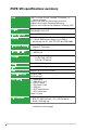
P5PE-VM specifications summary CPU LGA775 socket for Intel® Pentium® D/ Pentium® 4/ Celeron processor Supports Intel® Dual-Core 65nm Intel® processors Supports Intel® Hyper-Threading Technology Supports Intel® Enhanced Intel SpeedStep Technology (EIST) Chipset Northbridge: Intel® 865G Southbridge: Intel® ICH5 Front Side Bus 1066/800/533 MHz Memory Dual-channel memory architecture 2 x 184-pin DIMM sockets support up to 2GB of unbufferred non-ECC 400/333/266 MHz DDR DIMMs In
P5PE-VM specifications summary Industry standard PCI 2.2, USB 2.0 Manageability WfM 2.0, DMI 2.0, WOL by PME, WOR by PME Internal connectors 2 x USB 2.0 connectors for 4 additional USB 2.
xii
This chapter describes the motherboard features and the new technologies it supports.
1.1 Welcome! Thank you for buying an ASUS® P5PE-VM motherboard! The motherboard delivers a host of new features and latest technologies, making it another standout in the long line of ASUS quality motherboards! Before you start installing the motherboard, and hardware devices on it, check the items in your package with the list below. 1.2 Package contents Check your motherboard package for the following items.
Intel ® 65nanometer process technology support The motherboard supports Intel® processors built on the 65-nanometer (nm) process technology with copper interconnect. Intelʼs 65 nm process is the most advanced chip manufacturing technology, delivering breakthrough performance, enhanced media experience, and low power consumption. The Intel® 65 nm Dual-Core processors utilize this package technology for a thinner, lighter design without compromising performance.
Temperature, fan, and voltage monitoring The CPU temperature is monitored by the ASIC (integrated in the Winbond Super I/O) to prevent overheating and damage. The system fan rotations per minute (RPM) is monitored for timely xure detection. The ASIC monitors the voltage levels to ensure stable supply of current for critical components. 1.3.2 Innovative ASUS features ASUS EZ Flash BIOS With the ASUS EZ Flash, you can easily update the system BIOS even before loading the operating system.
1.4 Before you proceed Take note of the following precautions before you install motherboard components or change any motherboard settings. • Unplug the power cord from the wall socket before touching any component. • Use a grounded wrist strap or touch a safely grounded object or to a metal object, such as the power supply case, before handling components to avoid damaging them due to static electricity • Hold components by the edges to avoid touching the ICs on them.
1.5 Motherboard overview Before you install the motherboard, study the configuration of your chassis to ensure that the motherboard fits into it. Make sure to unplug the power cord before installing or removing the motherboard. Failure to do so can cause you physical injury and damage motherboard components. 1.5.1 Placement direction When installing the motherboard, make sure that you place it into the chassis in the correct orientation.
1.5.3 Motherboard layout 19.3cm (7.6in) KBPWR PS/2KBMS T: Mouse B: Keyboard ATX12V USB12 RJ-45 Top:Line In Center:Line Out Below:Mic In R Marvell 88E8001 PCI1 Super I/O SB_PWR PCI2 USB78 FP_AUDIO SPEAKER SEC_IDE AGP 4Mb BIOS Intel ICH5 CR2032 3V Lithium Cell CMOS Power PCI3 CHA_FAN USB3 USB4 PRI_IDE Intel 865G Bottom : Top: 24.5cm (9.
1.6 Central Processing Unit (CPU) The motherboard comes with a surface mount LGA775 socket designed for the Intel® Pentium® 4 processor in the 775-land package. 1.6.1 • Your boxed Intel® Pentium® 4 LGA775 processor package should come with installation instructions for the CPU, fan and heatsink assembly. If the instructions in this section do not match the CPU documentation, follow the latter.
2. Press the load lever with your thumb (A) and move it to the left (B) until it is released from the retention tab. Retention tab PnP Cap A Load lever B This side of the cam box should face you. To prevent damage to the socket pins, do not remove the PnP cap unless you are installing a CPU. 3. Lift the load lever in the direction of the arrow to a 135º angle. 4.
6. Close the load plate (A), then push the load lever (B) until it snaps into the retention tab. A B The CPU fits in only one correct orientation. DO NOT force the CPU into the socket to prevent bending the connectors on the socket and damaging the CPU! Notes on Intel ® Hyper-Threading Technology • This motherboard supports Intel® Pentium® 4 CPUs in the 775-land package with Hyper‑Threading Technology. • Hyper-Threading Technology is supported under Windows® XP/2003 Server and Linux 1.7.
1.6.2 Installing the CPU heatsink and fan The Intel Pentium® 4 LGA775 processor requires a specially designed heatsink and fan assembly to ensure optimum thermal condition and performance. ® • When you buy a boxed Intel® Pentium® 4 processor, the package includes the CPU fan and heatsink assembly. If you buy a CPU separately, make sure that you use only Intel®‑certified multi‑directional heatsink and fan.
2. Push down two fasteners at a time in a diagonal sequence to secure the heatsink and fan assembly in place. B A A B 3. A B B A Connect the CPU fan cable to the connector on the motherboard labeled CPU_FAN. P5PE-VM CPU_FAN GND CPU FAN PWR CPU FAN IN CPU FAN PWM R P5PE-VM CPU Fan Connector Do not forget to connect the CPU fan connector! Hardware monitoring errors can occur if you fail to plug this connector.
1.6.3 Uninstalling the CPU heatsink and fan To uninstall the CPU heatsink and fan: 1. Disconnect the CPU fan cable from the connector on the motherboard. 2. Rotate each fastener counterclockwise. 3. Pull up two fasteners at a time in a diagonal sequence to disengage the heatsink and fan assembly from the motherboard.
4. Carefully remove the heatsink and fan assembly from the motherboard. 5. Rotate each fastener clockwise to ensure correct orientation when reinstalling. Narrow end of the groove The narrow end of the groove should point outward after resetting. (The photo shows the groove shaded for emphasis.
1.7 System memory 1.7.1 Overview The motherboard comes with four 184-pin Double Data Rate (DDR) Dual Inline Memory Modules (DIMM) sockets. P5PE-VM The following figure illustrates the location of the sockets: R P5PE-VM 184-pin DDR DIMM Sockets 1.7.2 Channel Sockets Channel A DIMM_A1 Channel B DIMM_B1 Memory configurations You may install 64MB,128 MB, 256 MB, 512 MB, and 1 GB DDR DIMMs into the DIMM sockets using the memory configuration in this section.
1.7.3 DDR Qualified Vendors List The following table lists the memory modules that have been tested and qualified for use with this motherboard. Visit the ASUS website (www.asus. com) for the latest DDR DIMM modules for this motherboard.
1.7.4 Installing a DIMM Make sure to unplug the power supply before adding or removing DIMMs or other system components. Failure to do so may cause severe damage to both the motherboard and the components. 1. Unlock a DIMM socket by pressing the retaining clips outward. 2. Align a DIMM on the socket such that the notch on the DIMM matches the break on the socket. 2 DDR DIMM notch 1 1 Unlocked retaining clip A DDR DIMM is keyed with a notch so that it fits in only one direction.
1.8 Expansion slots In the future, you may need to install expansion cards. The following sub‑sections describe the slots and the expansion cards that they support. Make sure to unplug the power cord before adding or removing expansion cards. Failure to do so may cause you physical injury and damage motherboard components. 1.8.1 Installing an expansion card To install an expansion card: 1.
1.8.
1.8.4 PCI slots The PCI slots support cards such as a LAN card, SCSI card, USB card, and other cards that comply with PCI specifications. The figure shows a LAN card installed on a PCI slot. 1.8.5 AGP slot The Accelerated Graphics Port(AGP) slot that supports AGP8X/4X cards. when you buy an AGP card, make sure that you ask for one with +1.5V specification. Note the notches on the card golden fingers to ensure that they fit he AGP slot on your mother board. P5PE-VM Install only 1.5V or 0.
1.9 1. Jumpers Clear RTC RAM (3-pin CLRTC) This jumper allows you to clear the Real Time Clock (RTC) RAM in CMOS. You can clear the CMOS memory of date, time, and system setup parameters by erasing the CMOS RTC RAM data. The onboard button cell battery powers the RAM data in CMOS, which include system setup information such as system passwords. To erase the RTC RAM: 1. Turn OFF the computer and unplug the power cord. 2. Remove the onboard battery. 3.
2. Keyboard power (3-pin KBPWR) This jumper allows you to enable or disable the keyboard wake-up feature. Set this jumper to pins 2-3 (+5VSB) to wake up the computer when you press a key on the keyboard (the default is the Space Bar). This feature requires an ATX power supply that can supply at least 1A on the +5VSB lead, and a corresponding setting in the BIOS.
1.10 Connectors 1.10.1 Rear panel connectors 1 2 3 4 5 6 11 10 9 8 7 1. PS/2 mouse port (green). This port is for a PS/2 mouse. 2. Parallel port. This 25-pin port connects a parallel printer, a scanner, or other devices. 3. LAN (RJ-45) port. This port allows Gigabit connection to a Local Area Network (LAN) through a network hub. Refer to the table below for the LAN port LED indications.
Refer to the audio configuration table for the function of the audio ports in 2, 4, or 6-channel configuration. Audio 2, 4, or 6-channel configuration Port Headset 2-channel Light Blue 4-channel 6-channel Line In Line In Bass/Center Lime Line Out Front Speaker Out Front Speaker Out Pink Mic In Rear Speaker Out Rear Speaker Out 7. USB 2.0 ports 3 and 4. These two 4-pin Universal Serial Bus (USB) ports are available for connecting USB 2.0 devices. 8. USB 2.0 ports 1 and 2.
2. IDE connectors (40-1 pin PRI_IDE, SEC_IDE) These connectors are for Ultra DMA 100/66/33 signal cables. There are three interfaces on each Ultra DMA 100/66/33 signal cables: blue, black, and gray. Connect the blue interface into the motherboad’s IDE connector, then select the following modes to configure your hard disk drive(s).
3. Serial ATA connectors (7-pin SATA1, SATA2) P5PE-VM These connectors are for the Serial ATA signal cables for Serial ATA hard disk drives. P5PE-VM SATA Connectors SATA 2 GND RSATA_TXP2 RSATA_TXN2 GND RSATA_RXP2 RSATA_RXN2 GND GND RSATA_TXP1 RSATA_TXN1 GND RSATA_RXP1 RSATA_RXN1 GND SATA1 R Install the Windows® 2000 Service Pack 4 or the Windows® XP Service Pack1 or later before using Serial ATA. 4.
5. Speaker out connector (4-pin SPEAKER) P5PE-VM This connector is for the case-mounted speaker and allows you to hear system beeps and warnings. SPEAKER P5PE-VM Speaker Out Connector 6. +5V GND GND Speak Out 1 R Front panel audio connector (10-1 pin FP_AUDIO) R HP_HD AGND PRESENSE# MIC2_JD P5PE-VM This connector is for a chassis-mounted front panel audio I/O module that supports legacy AC ‘97 audio standard. Connect one end of the front panel audio I/O module cable to this connector.
7. ATX power connectors (20-pin ATXPWR, 4-pin ATX12V) These connectors are for an ATX power supply. The plugs from the power supply are designed to fit these connectors in only one orientation. Find the proper orientation and push down firmly until the connectors completely fit. • Do not forget to connect the 4-pin ATX +12 V power plug; otherwise, the system will not boot up. • Use a PSU with a minimum power rating of 300 W on this motherboard.
8. USB connectors (10-1 pin USB56, USB78) USB+5V USB_P8USB_P8+ GND NC P5PE-VM These connectors are for USB 2.0 ports. Connect the optional USB/GAME module cable to any of these connectors, then install the module to a slot opening at the back of the system chassis. These USB connectors comply with USB 2.0 specification that supports up to 480 Mbps connection speed. 1 USB+5V USB_P7USB_P7+ GND USB78 USB+5V USB_P6USB_P6+ GND NC R USB56 1 USB+5V USB_P5USB_P5+ GND P5PE-VM USB 2.
10. System panel connector (10-1 pin PANEL) P5PE-VM This connector supports several chassis-mounted functions. PLED+ PLEDPWR GND PLED PWRSW F_PANEL IDELED+ IDELEDGround Reset R HD LED RESET P5PE-VM System Panel Connector The sytem panel connector is color-coded for easy connection. Refer to the connector description below for details. 1-30 • System power LED (2-pin PLED) This 2-pin connector is for the system power LED. Connect the chassis power LED cable to this connector.
This chapter tells how to change the system settings through the BIOS Setup menus. Detailed descriptions of the BIOS parameters are also provided.
2.1 Managing and updating your BIOS The following utilities allow you to manage and update the motherboard Basic Input/Output System (BIOS) setup. 1. ASUS AFUDOS (Updates the BIOS in DOS mode using a bootable floppy disk.) 2. ASUS EZ Flash (Updates the BIOS using a floppy disk during POST.) 3. ASUS CrashFree BIOS 2 (Updates the BIOS using a bootable floppy disk or the motherboard support CD when the BIOS file fails or gets corrupted.) 4. ASUS Update (Updates the BIOS in Windows® environment.
d. From the Open field, type D:\bootdisk\makeboot a: assuming that D: is your optical drive. e. Press , then follow screen instructions to continue. 2. Copy the original or the latest motherboard BIOS file to the bootable floppy disk. 2.1.2 ASUS EZ Flash utility The ASUS EZ Flash feature allows you to update the BIOS without having to go through the long process of booting from a floppy disk and using a DOS‑based utility.
2.1.3 AFUDOS utility The AFUDOS utility allows you to update the BIOS file in DOS environment using a bootable floppy disk with the updated BIOS file. This utility also allows you to copy the current BIOS file that you can use as backup when the BIOS fails or gets corrupted during the updating process. Copying the current BIOS To copy the current BIOS file using the AFUDOS utility: • Make sure that the floppy disk is not write-protected and has at least 600 KB free space to save the file.
Updating the BIOS file To update the BIOS file using the AFUDOS utility: 1. Visit the ASUS website (www.asus.com) and download the latest BIOS file for the motherboard. Save the BIOS file to a bootable floppy disk. Write the BIOS filename on a piece of paper. You need to type the exact BIOS filename at the DOS prompt. 2. Copy the AFUDOS utility (afudos.exe) from the motherboard support CD to the bootable floppy disk you created earlier. 3.
2.1.4 ASUS Update utility The ASUS Update is a utility that allows you to manage, save, and update the motherboard BIOS in Windows® environment. The ASUS Update utility allows you to: • Save the current BIOS file • Download the latest BIOS file from the Internet • Update the BIOS from an updated BIOS file • Update the BIOS directly from the Internet, and • View the BIOS version information. This utility is available in the support CD that comes with the motherboard package.
Updating the BIOS through the Internet To update the BIOS through the Internet: 1. Launch the ASUS Update utility from the Windows® desktop by clicking Start > Programs > ASUS > ASUSUpdate > ASUSUpdate. The ASUS Update main window appears. 2. Select Update BIOS from the Internet option from the drop‑down menu, then click Next. ASUS P5PE-VM 3. Select the ASUS FTP site nearest you to avoid network traffic, or click Auto Select. Click Next.
4. From the FTP site, select the BIOS version that you wish to download. Click Next. 5. Follow the screen instructions to complete the update process. The ASUS Update utility is capable of updating itself through the Internet. Always update the utility to avail all its features. Updating the BIOS through a BIOS file To update the BIOS through a BIOS file: 2- 1. Launch the ASUS Update utility from the Windows® desktop by clicking Start > Programs > ASUS > ASUSUpdate > ASUSUpdate.
2.2 BIOS setup program This motherboard supports a programmable firmware chip that you can update using the provided utility described in section “2.1 Managing and updating your BIOS.” Use the BIOS Setup program when you are installing a motherboard, reconfiguring your system, or prompted to“Run Setup.” This section explains how to configure your system using this utility. Even if you are not prompted to use the Setup program, you can change the configuration of your computer in the future.
2.2.1 BIOS menu screen Menu items Menu bar Configuration fields System Time System Date Legacy Diskette A [11:51:19] [Mon 05/15/2006] [1.44M, 3.5 in] Primary IDE Master Primary IDE Slave Secondary IDE Master Secondary IDE Slave Third IDE Master Fourth IDE Master IDE Configuration :[Not :[Not :[Not :[Not :[Not :[Not Detected Detected] Detected] Detected] Detected] Detected] General help Use [ENTER], [TAB] or [SHIFT-TAB] to select a field. Use [+] or [-] to configure system time.
2.2.4 Menu items The highlighted item on the menu bar displays the specific items for that menu. For example, selecting Main shows the Main menu items. The other items (Advanced, Power, Boot, and Exit) on the menu bar have their respective menu items. 2.2.5 System Time System Date Legacy Diskette A Legacy Diskette B Primary IDE Master Primary IDE Slave Secondary IDE Master Secondary IDE Slave Third IDE Master Fourth IDE Master IDE Configuration [11:10:19] [Thu 03/27/2003] [1.44M, 3.
2.3 Main menu When you enter the BIOS Setup program, the Main menu screen appears, giving you an overview of the basic system information. Refer to section “2.2.1 BIOS menu screen” for information on the menu screen items and how to navigate through them. System Time System Date Legacy Diskette A Primary IDE Master Primary IDE Slave Secondary IDE Master Secondary IDE Slave Third IDE Master Fourth IDE Master IDE Configuration [11:51:19] [Mon 05/15/2006] [1.44M, 3.
2.3.4 Primary, Secondary Master/Slave, Third and Fourth IDE Master While entering Setup, the BIOS automatically detects the presence of IDE devices. There is a separate sub-menu for each IDE device. Select a device item then press to display the IDE device information.
PIO Mode [Auto] Selects the PIO mode. Configuration options: [Auto] [0] [1] [2] [3] [4] DMA Mode [Auto] Selects the DMA mode. Configuration options: [Auto] [SWDMA0] [SWDMA1] [SWDMA2] [MWDMA0] [MWDMA1] [MWDMA2] [UDMA0] [UDMA1] [UDMA2] [UDMA3] [UDMA4] [UDMA5] SMART Monitoring [Auto] Sets the Smart Monitoring, Analysis, and Reporting Technology. Configuration options: [Auto] [Disabled] [Enabled] 32Bit Data Transfer [Disabled] Enables or disables 32-bit data transfer.
The P-ATA+S-ATA and P-ATA options are for advanced users only. If you set to any of these options and encounter problems, revert to the default setting S-ATA. Configuration options: [P-ATA+S-ATA] [S‑ATA] [P-ATA] The IDE Port Settings item appears only when the Onboard IDE Operate Mode item is set to Compatible Mode. IDE Port Settings [Primary P-ATA+S-ATA] Allows you to select the IDE port to be used.
2.4 Advanced menu The Advanced menu items allow you to change the settings for the CPU and other system devices. Take caution when changing the settings of the Advanced menu items. Incorrect field values can cause the system to malfunction. CPU Configuration Chipset Onboard Devices Configuration PCIPnP USB Configuration 2.4.1 CPU Configuration The items in this menu show the CPU-related information that the BIOS automatically detects.
Max CPUID Value Limit [Disabled] Enable this item to boot legacy operating systems that cannot support CPUs with extended CPUID functions. Configuration options: [Disabled] [Enabled] Execute Disable Function [Disabled] Allows you to Enable/disable Execute Disable Function. Configuration options: [Disabled] [Enabled] Enhanced C1 Control [Auto] When set to [Auto], the BIOS will automatically check the CPU’s capability to enable the C1E support. In C1E mode, the CPU power consumption is lower when idle.
2.4.2 Chipset The Chipset menu allows you to change the advanced chipset settings. Select an item then press to display the sub-menu. Advanced Chipset Settings WARNING: Setting wrong values in below sections may cause the system to malfunction. Configure DRAM Timing by SPD [Enabled] Performance Acceleration Mode [Auto] DRAM Idle Timer [Auto] DRAM Refresh Rate [Auto] Graphic Adapter Priority [AGP/Int-VGA] Graphics Aperture Size [64MB] MPS Revision [1.
Performance Acceleration Mode [Auto] Enables or sets the performance acceleration mode. When Enabled, the CPU to memory latency is minimized to boost performance. Configuration options: [Enabled] [Auto] Setting to Enabled may cause the system to become unstable! If this happens, revert to the default setting [Auto]. DRAM Idle Timer [Auto] Sets the DRAM idle timer. Configuration options: [Infinite] [0T] [8T] [16T] [64T] [Auto] DRAM Refresh Rate [Auto] Sets the DRAM refresh rate.
2.4.3 Onboard Devices Configuration Onboard AC’97 Audio [Auto] Onboard LAN [Enabled] Onboard LAN Boot ROM [Disabled] Serial Port1 Address [3F8/IRQ4] Parallel Port Address [378] Parallel Port Mode [ECP] ECP Mode DMA Channel [DMA3] Parallel Port IRQ [IRQ7] Onboard AC’97 Audio [Auto] When set to Auto, the BIOS detects whether you are using any audio device. If an audio device is detected, the onboard audio controller is enable; if no audio device is detected, the controller is disabled.
2.4.4 PCI PnP The PCI PnP menu items allow you to change the advanced settings for PCI/PnP devices. The menu includes setting IRQ and DMA channel resources for either PCI/PnP or legacy ISA devices, and setting the memory size block for legacy ISA devices. Take caution when changing the settings of the PCI PnP menu items. Incorrect field values can cause the system to malfunction. Advanced PCI/PnP Settings WARNING: Setting wrong values in below sections may cause system to malfunction.
IRQ-xx assigned to [PCI Device] When set to [PCI Device], the specific IRQ is free for use of PCI/PnP devices. When set to [Reserved], the IRQ is reserved for legacy ISA devices. Configuration options: [PCI Device] [Reserved] 2.4.5 USB Configuration The items in this menu allows you to change the USB-related features. Select an item then press to display the configuration options. USB Configuration Module Version - 2.23.2-5.
USB Mass Storage Device Configuration USB Mass Storage Device Configuration USB Mass Storage Reset Delay [20 Sec] No USB Mass Storage device detected USB Mass Storage Reset Delay [20 Sec] Allows you to select the number of seconds POST waits for the USB mass storage device after the start unit command. The message “No USB mass storage device detected” appears if none is installed in the system.
2.5 Power menu The Power menu items allow you to change the settings for the Advanced Power Management (APM). Select an item then press to display the configuration options. Suspend Mode [Auto] ACPI 2.0 Support [No] ACPI APIC Support [Enabled] APM Configuration Hardware Monitor 2.5.1 Suspend Mode [Auto] Allows you to select the Advanced Configuration and Power Interface (ACPI) state to be used for system suspend. Configuration options: [S1 Only] [Auto] 2.5.2 ACPI 2.
2.5.4 APM Configuration APM Configuration Power Button Mode [On/Off] Restore on AC Power Loss [Power Off] Power On By RTC Alarm [Disabled] Resume On LAN [Enabled] Power On By External Modems [Enabled] Power On By PCI Devices [Enabled] Power On By PS/2 Keyboard [Ctrl-Esc] Power On By PS/2 Mouse [Enabled] Power Button Mode [On/Off] When the power button is pressed, the system goes into On/Off or Suspend.
Power On By PCI Devices [Enabled] When set to [Enabled], this parameter allows you to turn on the system through a PCI LAN or modem card. This feature requires an ATX power supply that provides at least 1A on the +5VSB lead. Configuration options: [Disabled] [Enabled] Power On By PS/2 Keyboard [Ctrl-Esc] Allows you to use specific keys on the keyboard to turn on the system. This feature requires an ATX power supply that provides at least 1A on the +5VSB lead.
CPU Fan Speed [xxxxRPM] or [N/A] The onboard hardware monitor automatically detects and displays the CPU fan speed in rotations per minute (RPM). If the fan is not connected to the motherboard, the field shows N/A. Chassis Fan Speed [xxxxRPM] or [N/A] The onboard hardware monitor automatically detects and displays the chassis fan speed in rotations per minute (RPM). If the fan is not connected to the chassis, the specific field shows N/A. VCORE Voltage, 3.
2.6 Boot menu The Boot menu items allow you to change the system boot options. Select an item then press to display the sub-menu. APM Configuration Boot Device Priority Boot Settings Configuration Security Enter F1 F10 ESC 2.6.
2.6.2 Boot Settings Configuration Boot Settings Configuration Quick Boot [Enabled] Full Screen Logo [Enabled] AddOn ROM Display Mode [Force BIOS] Bootup Num-Lock [On] PS/2 Mouse Support [Auto] Wait For ‘F1’ If Error [Enabled] Hit ‘DEL’ Message Display [Enabled] Interrupt 19 Capture [Disabled] Quick Boot [Enabled] Allows BIOS to skip certain tests while booting. This will decrease the time needed to boot the system.
Interrupt 19 Capture [Disabled] When set to [Enabled], this function allows the option ROMs to trap Interrupt 19. Configuration options: [Disabled] [Enabled] 2.6.3 Security The Security menu items allow you to change the system security settings. Select an item then press to display the configuration options. Security Settings Supervisor Password User Password : Not Installed : Not Installed to change password. again to disabled password.
Security Settings Supervisor Password User Password : Not Installed : Not Installed Change Supervisor Password User Access Level [Full Access] Change User Password Clear User Password Password Check [Setup] User Access Level [Full Access] Select Screen Select Item +Change Option F1 General Help F10 Save and Exit to Setup items.
2.7 Exit menu The Exit menu items allow you to load the optimal or failsafe default values for the BIOS items, and save or discard your changes to the BIOS items. Exit Options Exit & Save Changes Exit & Discard Changes Discard Changes Load Setup Defaults Exit system setup after saving the changes. F10 key can be used for this operation. Select Screen Pressing does not immediately exit this menu.
This chapter describes the contents of the support CD that comes with the motherboard package.
3.1 Installing an operating system This motherboard supports Windows® 98SE/2000/XP/2003 Server operating systems (OS). Always install the latest OS version and corresponding updates to maximize the features of your hardware. 3.2 • Motherboard settings and hardware options vary. Use the setup procedures presented in this chapter for reference only. Refer to your OS documentation for detailed information.
3.2.2 Drivers menu The drivers menu shows the available device drivers if the system detects installed devices. Install the necessary drivers to activate the devices. INTEL Chipset Driver Installs the Intel® Chipset driver. INTEL Onboard VGA Driver Installs the Intel® Onboard VGA driver. SoundMAX Audio Driver and Application Installs the SoundMax Audio driver and application. Marvell Yukon Gigabit Ethernet Driver Installs the Marvell® Yukon Gigabit Ethernet driver. USB2.
3.2.3 Utilities menu The Utilities menu shows the applications and other software that the motherboard supports. ASUS PC Probe This smart utility monitors the fan speed, CPU temperature, and system voltages, and alerts you of any detected problems. This utility helps you keep your computer in healthy operating condition. ASUS Update The ASUS Update utility allows you to update the motherboard BIOS in a Windows® environment.
3.2.4 ASUS Contact information Click the Contact tab to display the ASUS contact information. You can also find this information on the inside front cover of this user guide.
3- Chapter 3: Software support