Motherboard P5RD1-VM
C2229 © 2005 2
® ® ® 5
• • • • • • • • • • • • 6
• • • 7
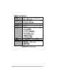
™ 1 2 Jumper Mode 8 2 3 Jumper Free (Default)
® ® ® ® ® ® ® ® ® ® ® 9
1-1
® ® ® ® ® ® 1-2
® ® ® ® ® ® 1-3
1-4
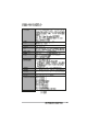
P5RD1-VM LED1 ® P5RD1-VM Onboard LED ON Standby Power OFF Powered Off 1-5
® 1-6 P5RD1-VM
24.3cm (9.6in) KBPWR CHASSIS PS/2KBMS T: Mouse B: Keyboard CHA_FAN ATX12V FLOPPY COM1 Super I/O CPU_FAN ATI RC410 TV-OUT Top:Line In Center:Line Out Below:Mic In EATXPWR SEC_IDE PRI_IDE CR2032 3V Lithium Cell CMOS Power RTL8201CL 21.8cm (8.
® ® • ® • • P5RD1-VM • ® P5RD1-VM CPU Socket 775 1-8
A B 1-9
A B 1-10
® • ® • ® ® • ® 1-11
1-12 B B A ® P5RD1-VM Fan connectors CPU_FAN CHA_FAN Rotation +12V GND A GND CPU FAN PWR CPU FAN IN CPU FAN PWM P5RD1-VM A B A B
B A A A B B B A 1-13
1-14
80 Pins 104 Pins P5RD1-VM DIMM1 P5RD1-VM 184-pin DDR DIMM sockets DIMM2 ® 1-15
1-16
1-17
1-18
1-19
1-20
A B C D E F G H 1-21
1-22
P5RD1-VM CLRTC 2 1 3 2 ® P5RD1-VM Clear RTC RAM Clear CMOS Normal (Default) 1-23
USBPW34 USBPW12 P5RD1-VM CLRTC 3 2 2 1 +5V (Default) +5VSB USBPW56 1 2 ® P5RD1-VM USB device wake-up 1-24 +5V (Default) USBPW78 2 3 +5VSB 3 2 2 1 +5V (Default) +5VSB
KBPWR P5RD1-VM 1 2 +5V 2 3 +5VSB (Default) ® P5RD1-VM Keyboard power setting 1-25
1 2 3 4 5 6 11 10 9 8 7 100M/ACT 10M/ACT LED LED LAN port 1-26
1-27
P5RD1-VM FLOPPY PIN 1 ® P5RD1-VM Floppy disk drive connector • P5RD1-VM IDE connectors 1-28 PRI_IDE ® SEC_IDE P5RD1-VM • PIN 1
P5RD1-VM SATA4 SATA1 ® SATA2 GND RSATA_TXP1 RSATA_TXN1 GND RSATA_RXP1 RSATA_RXN1 GND GND RSATA_TXP3 RSATA_TXN3 GND RSATA_RXP3 RSATA_RXN3 GND GND RSATA_TXP2 RSATA_TXN2 GND RSATA_RXP2 RSATA_RXN2 GND P5RD1-VM P5RD1-VM SATA connectors SATA3 GND RSATA_TXP4 RSATA_TXN4 GND RSATA_RXP4 RSATA_RXN4 GND Speak Out GND GND +5V SPEAKER ® 1 P5RD1-VM Speaker out connector 1-29
CHA_FAN GND CPU FAN PWR CPU FAN IN CPU FAN PWM Rotation +12V GND P5RD1-VM CPU_FAN ® SPDIFOUT GND +5V P5RD1-VM P5RD1-VM Fan connectors ® P5RD1-VM Digital audio connector 1-30 SPDIF_OUT
• • • ATX12V P5RD1-VM +12V DC GND ® P5RD1-VM ATX power connectors EATXPWR +12V DC GND +3 Volts -12 Volts Ground PSON# Ground Ground Ground -5 Volts +5 Volts +5 Volts +5 Volts Ground +3 Volts +3 Volts Ground +5 Volts Ground +5 Volts Ground Power OK +5V Standby +12 Volts +12 Volts +3 Volts 1-31
® P5RD1-VM Internal audio connectors 1-32 Right Audio Channel Ground Ground Left Audio Channel P5RD1-VM USB 2.
AAFP MIC2 MICPWR Line out_R NC Line out_L ® BLINE_OUT_L AGND +5VA BLINE_OUT_R SENSE2_RETUR Legacy AC’97 compliant definition PORT1 L PORT1 R PORT2 R SENSE_SEND PORT2 L GND PRESENCE# SENSE1_RETUR P5RD1-VM Azalia compliant definition P5RD1-VM Analog front panel connector P5RD1-VM CHASSIS GND Chassis Signal (Default) +5VSB_MB ® P5RD1-VM Chassis intrusion connector 1-33
PLED+ PLEDPWR GND P5RD1-VM PWR LED PWR BTN HDLED+ HDLEDGround Reset F_PANEL HD LED RESET ® * Requires an ATX power supply.
2-1
2-2
EZFlash starting BIOS update Checking for floppy... EZFlash starting BIOS update Checking for floppy... Floppy found! Reading file “P5RD1VM.ROM”. Completed. Start erasing.......| Start Programming...| Flashed successfully. Rebooting.
• • A:\>afudos /oOLDBIOS1.ROM A:\>afudos /oOLDBIOS1.ROM AMI Firmware Update Utility - Version 1.10 Copyright (C) 2002 American Megatrends, Inc. All rights reserved. Reading flash ..... done A:\> 2-4
A:\>afudos /iP5RD1VM.ROM A:\>afudos /iP5RD1VM.ROM AMI Firmware Update Utility - Version 1.10 Copyright (C) 2002 American Megatrends, Inc. All rights reserved. Reading file ..... done Erasing flash .... done Writing flash .... 0x0008CC00 (9%) A:\>afudos /iP5RD1VM.ROM AMI Firmware Update Utility - Version 1.10 Copyright (C) 2002 American Megatrends, Inc. All rights reserved. Reading file ..... done Erasing flash .... done Writing flash .... 0x0008CC00 (9%) Verifying flash .. done A:\> 2-5
Bad BIOS checksum. Starting BIOS recovery... Checking for floppy... Bad BIOS checksum. Starting BIOS recovery... Checking for floppy... Floppy found! Reading file “P5RD1VM.ROM”. Completed. Start flashing...
Bad BIOS checksum. Starting BIOS recovery... Checking for floppy... Bad BIOS checksum. Starting BIOS recovery... Checking for floppy... Floppy not found! Checking for CD-ROM... CD-ROM found. Reading file “P5RD1VM.ROM”. Completed. Start flashing...
2-8
2-9
2-10
2-11
System Time System Date Legacy Diskette A Primary IDE Master Primary IDE Slave Third IDE Master Third IDE Slave Fourth IDE Master Fourth IDE Slave IDE Configuration System Information 2-12 : : : : : : [11:51:19] [Thu 06/10/2004] [1.44M, 3.5 in] Use [ENTER], [TAB] or [SHIFT-TAB] to select a field. [ST320413A] [Pioneer CD-ROM ATA] [Not Detected] [Not Detected] [Not Detected] [Not Detected] Use [+] or [-] to configure the System time.
System Time System Date Legacy Diskette A [11:51:19] [Thu 06/10/2004] [1.44M, 3.5 in] Primary IDE Master : [ST320413A] Primary IDE Slave : [Pioneer CD-ROM ATA] Third IDE Master : [Not Detected] Third IDE Slave : [Not Detected] Fourth IDE Master : [Not Detected] Fourth IDE Slave : [Not Detected] IDE Configuration Use [ENTER], [TAB] or [SHIFTTAB] to select a field. Use [+] or [-] to configure the System time.
System Time System Date Legacy Diskette A Primary IDE Master Primary IDE Slave Third IDE Master Third IDE Slave Fourth IDE Master Fourth IDE Slave IDE Configuration System Information 2-14 : : : : : : [11:51:19] [Thu 06/10/2004] [1.44M, 3.5 in] Use [ENTER], [TAB] or [SHIFT-TAB] to select a field. [ST320413A] [Pioneer CD-ROM ATA] [Not Detected] [Not Detected] [Not Detected] [Not Detected] Use [+] or [-] to configure the System time.
Primary IDE Master Device Vendor Size LBA Mode Block Mode PIO Mode Async DMA Ultra DMA SMART Monitoring : : : : : : : : : Hard Disk ST320413A 20.0GB Supported 16 Sectors Supported MultiWord DMA-2 Ultra DMA-5 Supported Select the type of device connected to the system.
AMIBIOS Version : 0109 Build Date : 08/11/05 Processor Type Speed Count : Genuine Intel(R) CPU 3.
Configure the USB support. JumperFree Configuration USB Configuration CPU Configuration Chipset Onboard Devices Configuration PCI PnP USB Configuration Module Version - 2.24.0-10.4 USB Devices Enabled: None USB Controller Legacy USB Support USB 2.
2-18
Configure System Frequency/Voltage AI Overclocking [Auto] FSB 1066 266 MHZ FSB 800 200 MHz FSB 533 133 MHz 2-19
2-20
Configure Advanced CPU settings Manufacturer: Brand String: Frequency : FSB Speed : Cache L1 Cache L2 Cache L3 Intel Genuine Intel(R) CPU 3.20GHz 3200 MHz 800 MHz : 16 KB : 1024 KB : 0 KB Ratio Status: Unlocked (Max:16, Ratio Actual Value : 16 Ratio CMOS Setting: Hyper Threading Technology Microcode Updation: Max CPUID Value Limit: CPU Internal Thermal Control Sets the ratio between CPU Core Clock and the FSB Frequency. NOTE: If an invalid ratio is set in CMOS then actual and setpoint values may differ.
Chipset Settings NorthBridge Configuration SouthBridge Configuration Memory Reference Code(MRC) Version 5.
DRAM 1T/2T Command Configure DRAM Timing by SPD DRAM CAS Select DRAM tRP Select DRAM tRCD Select DRAM tRAS Select Refresh Rate Select [2T] [Enabled] [3.0 Clocks] [3.0 Clocks] [3.0 Clocks] [8.0 Clocks] [7.
2-24 AC’97 & Azalia LINK A Serial ATA Controller M1573 RAID Function [Azalia Only] [Enabled] [Enabled] Onboard LAN OnBoard LAN Boot ROM [Enabled] [Disabled]
Configure ITE8712 Super IO Chipset Serial Port1 Address [3F8/IRQ4] Parallel Port Address [378] Advanced PCI/PnP Settings WARNING: Setting wrong values in below sections may cause system to malfunction.
2-26
Suspend Mode Repost Video on S3 Resume ACPI 2.0 Support ACPI APIC Support [Auto] [No] [No] [Enabled] Select the ACPI state used for System Suspend.
APM Configuration Restore on AC Power Loss Power On By RTC Alarm Power On By External Modems Power On By PCI Devices Power On By PCIE Devices Power On By PS/2 Keyboard Power On By PS/2 Mouse 2-28 [Power Off] [Disabled] [Disabled] [Disabled] [Disabled] [Disabled] [Disabled] Go into On/Off or Suspend when Power button is pressed.
Hardware Monitor CPU Temperature MB Temperature [32.5ºC/90.5ºF] [36.0ºC/96.5ºF] CPU Fan Speed (RPM) Chassis Fan Speed (RPM) [3813 RPM] [N/A] VCORE Voltage 3.3V Voltage 5V Voltage 12V Voltage [ 1.320V] [ 3.345V] [ 5.094V] [11.
2-30
Boot Settings Specifies the Boot Device Priority sequence Boot Device Priority Boot Settings Configuration Security Boot Device Priority 1st Boot Device 2nd Boot Device 3rd Boot Device [1st FLOPPY DRIVE] [PM-ST330620A] [PS-Pioneer CD-ROM] 2-31
Boot Settings Configuration Quick Boot Full Screen Logo AddOn ROM Display Mode Bootup Num-Lock PS/2 Mouse Support Wait For ‘F1’ If Error Hit ‘DEL’ Message Display Interrupt 19 Capture 2-32 [Enabled] [Enabled] [Force BIOS] [On] [Auto] [Enabled] [Enabled] [Disabled] Allows BIOS to skip certain tests while booting. This will decrease the time needed to boot the system.
Security Settings Supervisor Password User Password : Not Installed : Not Installed to change password. again to disabled password.
Security Settings Supervisor Password User Password 2-34 : Not Installed : Not Installed Change Supervisor Password User Access Level Change User Password Clear User Password Password Check [Setup] Boot Sector Virus Protection [Disabled] [Full Access]
Exit Options Exit & Save Changes Exit & Discard Changes Discard Changes Load Setup Defaults 2-35
2-36
3-1
3-2
3-3
3-4
3-5
3-6
3-7
® ® ®
® ® ® ® ® ® ® ® ® ® ® ® A-1
Configure Advanced CPU settings Frequency FSB Speed Maximum: CPU speed is set to maximum. Minimum: CPU speed is set to minimum. Automatic: CPU speed is controlled by the operating system. Disabled: Default CPU speed.
® ® ® A-3
A-4