User Guide Motherboard P5VD1-X
E2180 First Edition July 2005 Copyright © 2005 ASUSTeK COMPUTER INC. All Rights Reserved. No part of this manual, including the products and software described in it, may be reproduced, transmitted, transcribed, stored in a retrieval system, or translated into any language in any form or by any means, except documentation kept by the purchaser for backup purposes, without the express written permission of ASUSTeK COMPUTER INC. (“ASUS”).
Contents Contents ........................................................................................................ iii Notices ..........................................................................................................vi Safety information ......................................................................................... vii About this guide ........................................................................................... viii Typography .............................
Contents 2.7.1 Rear panel connectors .................................................. 2-20 2.7.2 Internal connectors ....................................................... 2-22 Chapter 3: Powering up 3.1 Starting up for the first time ............................................................ 3-1 3.2 Powering off the computer ............................................................. 3-2 3.2.1 Using the OS shut down function.................................... 3-2 3.2.
Contents 4.5 4.6 4.7 4.4.2 USB Configuration ........................................................ 4-17 4.4.3 CPU Configuration ........................................................ 4-18 4.4.4 Chipset .......................................................................... 4-19 4.4.5 Onboard Devices Configuration .................................... 4-23 4.4.6 PCI PnP ........................................................................ 4-24 Power menu .................................
Notices Federal Communications Commission Statement This device complies with Part 15 of the FCC Rules. Operation is subject to the following two conditions: • This device may not cause harmful interference, and • This device must accept any interference received including interference that may cause undesired operation. This equipment has been tested and found to comply with the limits for a Class B digital device, pursuant to Part 15 of the FCC Rules.
Safety information Electrical safety • To prevent electrical shock hazard, disconnect the power cable from the electrical outlet before relocating the system. • When adding or removing devices to or from the system, ensure that the power cables for the devices are unplugged before the signal cables are connected. If possible, disconnect all power cables from the existing system before you add a device.
About this guide This user guide contains the information you need when installing and configuring the motherboard. How this guide is organized This manual contains the following parts: • Chapter 1: Product introduction This chapter describes the features of the motherboard and the new technology it supports. • Chapter 2: Hardware information This chapter lists the hardware setup procedures that you have to perform when installing system components.
Conventions used in this guide To make sure that you perform certain tasks properly, take note of the following symbols used throughout this manual. DANGER/WARNING: Information to prevent injury to yourself when trying to complete a task. CAUTION: Information to prevent damage to the components when trying to complete a task. IMPORTANT: Instructions that you MUST follow to complete a task NOTE: Tips and additional information to help you complete a task.
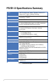
P5VD1-X Specifications Summary CPU LGA775 socket for Intel® Pentium® D/Pentium® 4/Celeron CPU Supports Intel® Hyper-Threading Technology Chipset Northbridge: VIA PT880Ultra Southbridge: VT 8237R Front Side Bus 1066/800/533 MHz Memory Dual-channel memory architecture 4 x 184-pin DIMM sockets support up to 4GB of unbuffered non-ECC 400/333 MHz DDR memory modules Expansion slots 1 x AGP8X slot 1 x Universal PCI Express x16 slot (max.
P5VD1-X Specifications Summary Rear panel I/O Ports 1 x Parallel port 1 x COM Port 1 x Coaxial S/PDIF out port 1 x PS/2 Keyboard port 1 x PS/2 Mouse port 1 x LAN (RJ-45) port 1 x Line In port 1 x Line Out port 1 x Microphone port 4 x USB 2.0/1.1 ports Internal connectors 2 x USB 2.0 connectors for 4 additional USB 2.
xii
This chapter describes the motherboard features and the new technologies it supports.
Chapter Summary 1.1 Welcome! ....................................................................................... 1-1 1.2 Package contents........................................................................... 1-1 1.3 Special features .............................................................................
1.1 Welcome! Thank you for buying an ASUS® P5VD1-X motherboard! The motherboard delivers a host of new features and latest technologies, making it another standout in the long line of ASUS quality motherboards! Before you start installing the motherboard, and hardware devices on it, check the items in your package with the list below. 1.2 Package contents Check your motherboard package for the following items.
1.3 Special features 1.3.1 Product highlights Intel LGA775 Pentium 4 CPU This motherboard supports the latest Pentium 4 CPU from Intel in LGA775 package. With 1066/800/533MHz FSB, Hyper-Threading Technology and corespeeds up to 3.8GHz and beyond, Intelʼs LGA775 Pentium 4 is one of the fastest desktop processors to date.
Dual-Core CPU Enjoy the extraordinary CPU power from the latest dual-core CPU. The advanced processing technology contains two physical CPU cores with individually dedicated L2 cache to satisfy the rising demand for more powerful processing capability. 64-bit CPU support 64-bit computing, the next generation technology to replace current 32-bit architecture, delivers advanced system performance, faster memory access and increased productivity.
1.3.2 Innovative ASUS features ASUS CrashFree BIOS 2 The CrashFree BIOS2 feature now includes the BIOS auto-recovery function in a support CD. Users can reboot their system through the support CD when a bootable disk is not available, and go through the simple BIOS auto-recovery process. ASUS motherboards now enable users to enjoy this protection feature without the need to pay for an optional ROM.
This chapter lists the hardware setup procedures that you have to perform when installing system components. It includes description of the jumpers and connectors on the motherboard.
Chapter Summary 2.1 Before you proceed ........................................................................ 2-1 2.2 Motherboard overview.................................................................... 2-2 2.3 Central Processing Unit (CPU) ...................................................... 2-4 2.4 System memory ............................................................................. 2-9 2.5 Expansion slots ............................................................................
2.1 Before you proceed Take note of the following precautions before you install motherboard components or change any motherboard settings. • Unplug the power cord from the wall socket before touching any component. • Use a grounded wrist strap or touch a safely grounded object or to a metal object, such as the power supply case, before handling components to avoid damaging them due to static electricity • Hold components by the edges to avoid touching the ICs on them.
2.2 Motherboard overview Before you install the motherboard, study the configuration of your chassis to ensure that the motherboard fits into it. Make sure to unplug the power cord before installing or removing the motherboard. Failure to do so can cause you physical injury and damage motherboard components. 2.2.1 Placement direction When installing the motherboard, make sure that you place it into the chassis in the correct orientation.
2.2.3 Motherboard layout 22.9cm( 9.0in) PS/2KBMS T: Mouse B: Keyboard ATX12V VIA PT880Ultra CPU_FAN 30.5cm (12.
2.3 Central Processing Unit (CPU) The motherboard comes with a surface mount LGA775 socket designed for the Intel® Pentium® 4 processor in the 775-land package. 2.3.1 • Your boxed Intel® Pentium® 4 LGA775 processor package should come with installation instructions for the CPU, fan and heatsink assembly. If the instructions in this section do not match the CPU documentation, follow the latter.
2. Press the load lever with your thumb (A) and move it to the left (B) until it is released from the retention tab. Retention tab PnP Cap A Load lever B This side of the cam box should face you. To prevent damage to the socket pins, do not remove the PnP cap unless you are installing a CPU. 3. Lift the load lever in the direction of the arrow to a 135º angle. 4. Lift the load plate with your thumb and forefinger to a 100º angle (A), then push the PnP cap from the load plate window to remove (B).
6. Close the load plate (A), then push the load lever (B) until it snaps into the retention tab. A B The CPU fits in only one correct orientation. DO NOT force the CPU into the socket to prevent bending the connectors on the socket and damaging the CPU! Notes on Intel® Hyper-Threading Technology • This motherboard supports Intel® Pentium® 4 CPUs in the 775-land package with Hyper-Threading Technology. • Hyper-Threading Technology is supported under Windows® XP/2003 Server and Linux 2.4.
2.3.2 Installing the CPU heatsink and fan The Intel® Pentium® 4 LGA775 processor requires a specially designed heatsink and fan assembly to ensure optimum thermal condition and performance. • Install the motherboard to the chassis before you install the CPU fan and heatsink assembly • When you buy a boxed Intel ® Pentium ® 4 processor, the package includes the CPU fan and heatsink assembly. If you buy a CPU separately, make sure that you use only Intel®-certified multi-directional heatsink and fan.
2. Push each of the pins downward to secure the heatsink and fan assembly in place. 3. When the fan and heatsink assembly is in place, connect the CPU fan cable to the connector on the motherboard labeled CPU_FAN. P5VD1-X ® CPU FAN PWM CPU FAN IN CPU FAN PWR GND CPU_FAN P5VD1-X CPU Fan connector Do not forget to connect the CPU fan connector! Hardware monitoring errors can occur if you fail to plug this connector.
2.4 System memory 2.4.1 Overview The motherboard comes with four 184-pin Double Data Rate (DDR) Dual Inline Memory Modules (DIMM) sockets. The following figure illustrates the location of the sockets: P5VD1-X 2.4.2 DIMM_B2 DIMM_B1 DIMM_A2 P5VD1-X 184-pin DDR DIMM sockets DIMM_A1 ® Memory Configurations You may install 256 MB, 512 MB and 1 GB unbuffered non-ECC DDR DIMMs into the DIMM sockets using the memory configurations in this section.
DDR400 Qualified Vendors List Size Vendor 256MB 512MB 256MB 512MB 256MB 512MB 256MB 512MB 256MB 1GB 256MB 512MB 256MB 512MB 256MB 512MB 256MB 512MB 256MB 256MB 512MB 512MB 256MB 512MB 512MB 512MB 256MB 256MB 512MB 256MB 512MB 256MB 512MB 256MB 256MB 512MB 512MB 256MB 512MB 256MB 256MB 512MB 512MB 512MB 256MB 512MB 256MB 512MB 256MB 512MB 256MB 512MB 256MB 512MB 256MB 512MB KINGSTON KINGSTON KINGSTON KINGSTON KINGSTON KINGSTON KINGSTON KINGSTON KINGSTON KINGSTON Infineon Infineon Infineon Infineon HY HY HY HY
DDR400 Qualified Vendors List Size Vendor 256MB 512MB 256MB 512MB 256MB 256MB 512MB 512MB 256MB 256MB 512MB 256MB 512MB 512MB 512MB 256MB Apacer Apacer Apacer Apacer Smart Smart Smart Smart TwinMOS TwinMOS TwinMOS Promos Promos BiaoXing Patriot Vdata Model 77.10636.46G 77.90728.U1G 77.10636.56G 77.10736.
2.4.3 Installing a DIMM Make sure to unplug the power supply before adding or removing DIMMs or other system components. Failure to do so may cause severe damage to both the motherboard and the components. 1. Unlock a DIMM socket by pressing the retaining clips outward. 2. Align a DIMM on the socket such that the notch on the DIMM matches the break on the socket. 2 DDR DIMM notch 1 1 Unlocked retaining clip A DDR DIMM is keyed with a notch so that it fits in only one direction.
2.5 Expansion slots In the future, you may need to install expansion cards. The following sub-sections describe the slots and the expansion cards that they support. Make sure to unplug the power cord before adding or removing expansion cards. Failure to do so may cause you physical injury and damage motherboard components. 2.5.1 Installing an expansion card To install an expansion card: 1.
2.5.
2.5.4 PCI slots The PCI slots support cards such as a LAN card, SCSI card, USB card, and other cards that comply with PCI specifications. The figure shows a LAN card installed on a PCI slot. 2.5.5 AGP slot The Accelerated Graphics Port (AGP) slot supports AGP 8X/4X (+1.5V) cards. When you buy an AGP card, make sure that you ask for one with +1.5V specification. Note the notches on the card golden fingers to ensure that they fit the AGP slot on the motherboard. Install only +1.5V or +0.8V AGP cards.
VGA Qualified Vender List PCIe X 16 VGA Card Abit RX300SE-PCIE Rev. V1.0 (BIOS: V008.015) PCIe _ 4X Pass ASUS EN5750/128 Rev. 1.01 (BIOS: V04.32.20.38.00) (BIOS: V5.43.02.16.AS27) Pass (BIOS: V4.35.20.45.E0) Pass (BIOS: V5.40.02.36.09) Pass Rev. B Pass Rev. V1.00 Pass Rev. 1.01 Pass (BIOS: V5.41.02.17.AS01) Pass (BIOS: V5.43.02.16.E1) Pass (BIOS: V009.004.001.032) ASUS P5VD1-X Motherboard Pass Rev. A1 (BIOS: V5.43.02.36.68) Pass Rev.V2.00 (BIOS: V8.015) Pass Rev. V1.00 (BIOS: V5D57.
VGA Qualified Vender List PCIe X 16 VGA Card MSI NX6600GT-TD128E PCIe _ 4X Rev.V200 Pass (BIOS: V5.43.02.16) ASUS EAX600XT Rev. V1.02 (BIOS:V113-AA20306-100AS) Gigabyte GV-NX66T128D (BIOS: V5.43.02.16) ASUS EN6800ULTRA (BIOS: V5.40.02.32.AS07) Albatron PCX5750 (BIOS: V4.36.20.38) Pass PCIe X 16 VGA Card PCIe _ 4X Rev V1.00A Pass ASUS EN6600 (BIOS: V5.43.02.16.AS11) Leadtek WinFast PX6600GT TDH Rev. A (BIOS: V5.43.02.16) Pass Pass Pass Albatron PC6200 (BIOS: V5.43.02.
2.6 Jumpers 1. Clear RTC RAM (CLRTC) This jumper allows you to clear the Real Time Clock (RTC) RAM in CMOS. You can clear the CMOS memory of date, time, and system setup parameters by erasing the CMOS RTC RAM data. The onboard button cell battery powers the RAM data in CMOS, which include system setup information such as system passwords. To erase the RTC RAM: 1. Turn OFF the computer and unplug the power cord. 2. Remove the onboard battery. 3. Move the jumper cap from pins 1-2 (default) to pins 2-3.
2. USB device wake-up (3-pin USBPW12, USBPW34, USBPW56, USBPW78) Set these jumpers to +5V to wake up the computer from S1 sleep mode (CPU stopped, DRAM refreshed, system running in low power mode) using the connected USB devices. Set to +5VSB to wake up from S3 and S4 sleep modes (no power to CPU, DRAM in slow refresh, power supply in reduced power mode). The USBPWR12 and USBPWR34 jumpers are for the rear USB ports.
2.7 Connectors 2.7.1 Rear panel connectors 1 2 3 4 5 6 11 9 10 8 7 1. PS/2 mouse port (green). This port is for a PS/2 mouse. 2. Parallel port. This 25-pin port connects a parallel printer, a scanner, or other devices. 3. LAN (RJ-45) port. This port allows Gigabit connection to a Local Area Network (LAN) through a network hub. Refer to the table below for the LAN port LED indications.
Audio 2, 4, or 6-channel configuration Port Light Blue Headset 2-channel 4-channel 6-channel Line In Line In Bass/Center Lime Line Out Front Speaker Out Front Speaker Out Pink Mic In Rear Speaker Out Rear Speaker Out 7. USB 2.0 ports 3 and 4. These two 4-pin Universal Serial Bus (USB) ports are available for connecting USB 2.0 devices. 8. USB 2.0 ports 1 and 2. These two 4-pin Universal Serial Bus (USB) ports are available for connecting USB 2.0 devices. 9. Serial connector.
2.7.2 Internal connectors 1. Floppy disk drive connector (34-1 pin FLOPPY) This connector is for the provided floppy disk drive (FDD) signal cable. Insert one end of the cable to this connector, then connect the other end to the signal connector at the back of the floppy disk drive. Pin 5 on the connector is removed to prevent incorrect cable connection when using an FDD cable with a covered Pin 5. FLOPPY PIN 1 P5VD1-X ® NOTE: Orient the red markings on the floppy ribbon cable to PIN 1.
3. Serial ATA connectors (7-pin SATA1, SATA2) These connectors are for the Serial ATA signal cables which are for Serial ATA hard disk drives. If you installed Serial ATA hard disk drives, you can create a RAID 0 or RAID 1 configuration through the onboard VIA® VT8237R RAID controller. Please refer to Chapter 5 for information on creating a RAID configuration. These connectors are set to Standard IDE configuration by default.
4. CPU and Chassis fan connectors (4-pin CPU_FAN, 3-pin CHA_FAN) The fan connectors support cooling fans of 350mA~740mA (8.88W max.) or a total of 1A~2.22A (26.64W max.) at +12V. Connect the fan cables to the fan connectors on the motherboard, making sure that the black wire of each cable matches the ground pin of the connector. Do not forget to connect the fan cables to the fan connectors. Insufficient air flow inside the system may damage the motherboard components.
6. ATX power connectors (24-pin EATXPWR, 4-pin ATX12V) These connectors are for an ATX power supply. The plugs from the power supply are designed to fit these connectors in only one orientation. Find the proper orientation and push down firmly until the connectors completely fit. • It is recommended that you use an ATX 12 V Specification 2.0-compliant power supply unit (PSU) with a minimum of 300 W power rating. This PSU type has 24-pin and 4-pin power plugs.
7. Internal audio connectors (4-pin CD, AUX) These connector allow you to receive stereo audio input from sound sources such as a CD-ROM, TV tuner, or MPEG card. CD(Black) AUX(White) P5VD1-X Left Audio Channel Ground Ground Right Audio Channel ® Left Audio Channel Ground Ground Right Audio Channel P5VD1-X Internal audio connectors 8. GAME port connector (16-1 pin GAME) +5V J1B2 J1CY GND GND J1CX J1B1 +5V This connector is for a GAME/MIDI port.
9. Front panel audio connector (10-1 pin FP_AUDIO) P5VD1-X FP_AUDIO MIC2 MICPWR Line out_R NC Line out_L ® BLINE_OUT_L AGND +5VA BLINE_OUT_R This is an interface for the front panel cable that allows convenient connection and control of audio devices. P5VD1-X Front panel audio connector Be default, the pins labeled LINE OUT_R/BLINE_OUT_R and the pins LINE OUT_L/BLINE_OUT_L are shorted with jumper caps. Remove the caps only when you are connecting the front panel audio cable.
10. System panel connector (20-pin PANEL) This connector supports several chassis-mounted functions. SPEAKER +5V Ground Ground Speaker PLED- PLED+ PLED ® IDE_LED Reset Ground P5VD1-X PWR Ground IDE_LED+ IDE_LED- PANEL RESET PWRSW * Requires an ATX power supply. P5VD1-X System Panel connector The sytem panel connector is color-coded for easy connection. Refer to the connector description below for details.
This chapter describes the power up sequence, the vocal POST messages, and ways of shutting down the system.
Chapter Summary 3.1 Starting up for the first time ............................................................ 3-1 3.2 Powering off the computer .............................................................
3.1 Starting up for the first time 1. After making all the connections, replace the system case cover. 2. Be sure that all switches are off. 3. Connect the power cord to the power connector at the back of the system chassis. 4. Connect the power cord to a power outlet that is equipped with a surge protector. 5. Turn on the devices in the following order: 6. a. Monitor b. External SCSI devices (starting with the last device on the chain) c.
3.2 Powering off the computer 3.2.1 Using the OS shut down function If you are using Windows® 2000: 1. Click the Start button then click Shut Down. 2. Make sure that the Shut Down option button is selected, then click the OK button to shut down the computer. 3. The power supply should turn off after Windows® shuts down. If you are using Windows® XP: 1. Click the Start button then select Turn Off Computer. 2. Click the Turn Off button to shut down the computer. 3.
This chapter tells how to change the system settings through the BIOS Setup menus. Detailed descriptions of the BIOS parameters are also provided.
Chapter Summary 4.1 Managing and updating your BIOS ................................................ 4-1 4.2 BIOS setup program .................................................................... 4-10 4.3 Main menu ................................................................................... 4-13 4.4 Advanced menu ........................................................................... 4-16 4.5 Power menu .................................................................................
4.1 Managing and updating your BIOS The following utilities allow you to manage and update the motherboard Basic Input/Output System (BIOS) setup. 1. ASUS AFUDOS (Updates the BIOS in DOS mode using a bootable floppy disk.) 2. ASUS EZ Flash (Updates the BIOS using a floppy disk during POST.) 3. ASUS CrashFree BIOS 2 (Updates the BIOS using a bootable floppy disk or the motherboard support CD when the BIOS file fails or gets corrupted.) 4. ASUS Update (Updates the BIOS in Windows® environment.
d. From the Open field, type D:\bootdisk\makeboot a: assuming that D: is your optical drive. e. Press , then follow screen instructions to continue. 2. Copy the original or the latest motherboard BIOS file to the bootable floppy disk. 4.1.2 ASUS EZ Flash utility The ASUS EZ Flash feature allows you to update the BIOS without having to go through the long process of booting from a floppy disk and using a DOS-based utility.
4.1.3 AFUDOS utility The AFUDOS utility allows you to update the BIOS file in DOS environment using a bootable floppy disk with the updated BIOS file. This utility also allows you to copy the current BIOS file that you can use as backup when the BIOS fails or gets corrupted during the updating process. Copying the current BIOS To copy the current BIOS file using the AFUDOS utility: • Make sure that the floppy disk is not write-protected and has at least 600 KB free space to save the file.
Updating the BIOS file To update the BIOS file using the AFUDOS utility: 1. Visit the ASUS website (www.asus.com) and download the latest BIOS file for the motherboard. Save the BIOS file to a bootable floppy disk. Write the BIOS filename on a piece of paper. You need to type the exact BIOS filename at the DOS prompt. 2. Copy the AFUDOS utility (afudos.exe) from the motherboard support CD to the bootable floppy disk you created earlier. 3.
4.1.4 ASUS CrashFree BIOS 2 utility The ASUS CrashFree BIOS 2 is an auto recovery tool that allows you to restore the BIOS file when it fails or gets corrupted during the updating process. You can update a corrupted BIOS file using the motherboard support CD or the floppy disk that contains the updated BIOS file. • • Prepare the motherboard support CD or the floppy disk containing the updated motherboard BIOS before using this utility.
Recovering the BIOS from the support CD To recover the BIOS from the support CD: 1. Remove any floppy disk from the floppy disk drive, then turn on the system. 2. Insert the support CD to the optical drive. 3. The utility displays the following message and automatically checks the floppy disk for the original or updated BIOS file. Bad BIOS checksum. Starting BIOS recovery... Checking for floppy...
4.1.5 ASUS Update utility The ASUS Update is a utility that allows you to manage, save, and update the motherboard BIOS in Windows® environment. The ASUS Update utility allows you to: • Save the current BIOS file • Download the latest BIOS file from the Internet • Update the BIOS from an updated BIOS file • Update the BIOS directly from the Internet, and • View the BIOS version information. This utility is available in the support CD that comes with the motherboard package.
Updating the BIOS through the Internet To update the BIOS through the Internet: 4-8 1. Launch the ASUS Update utility from the Windows® desktop by clicking Start > Programs > ASUS > ASUSUpdate > ASUSUpdate. The ASUS Update main window appears. 2. Select Update BIOS from the Internet option from the drop-down menu, then click Next. 3. Select the ASUS FTP site nearest you to avoid network traffic, or click Auto Select. Click Next.
4. From the FTP site, select the BIOS version that you wish to download. Click Next. 5. Follow the screen instructions to complete the update process. The ASUS Update utility is capable of updating itself through the Internet. Always update the utility to avail all its features. Updating the BIOS through a BIOS file To update the BIOS through a BIOS file: 1. Launch the ASUS Update utility from the Windows ® desktop by clicking Start > Programs > ASUS > ASUSUpdate > ASUSUpdate.
4.2 BIOS setup program This motherboard supports a programmable firmware chip that you can update using the provided utility described in section “4.1 Managing and updating your BIOS.” Use the BIOS Setup program when you are installing a motherboard, reconfiguring your system, or prompted to “Run Setup”. This section explains how to configure your system using this utility. Even if you are not prompted to use the Setup program, you can change the configuration of your computer in the future.
4.2.1 BIOS menu screen Menu items Menu bar Configuration fields General help v02.58 (C)Copyright 1985-2004, American Megatrends, Inc. Sub-menu items 4.2.
4.2.4 Menu items The highlighted item on the menu bar displays the specific items for that menu. For example, selecting Main shows the Main menu items. The other items (Advanced, Power, Boot, and Exit) on the menu bar have their respective menu items. 4.2.5 System Time System Date Legacy Diskette A Legacy Diskette B [11:51:19] [Sun 01/16/2005] [1.44M, 3.5 in] [Disabled] Primary IDE Master Primary IDE Slave Secondary IDE Master Secondary IDE Slave Use [ENTER], [TAB] or [SHIFT-TAB] to select a field.
4.3 Main menu When you enter the BIOS Setup program, the Main menu screen appears, giving you an overview of the basic system information. Refer to section “4.2.1 BIOS menu screen” for information on the menu screen items and how to navigate through them. System System Legacy Legacy Time Date Diskette A Diskette B Primary IDE Master Primary IDE Slave Secondary IDE Master Secondary IDE Slave [11:51:19] [Sun 01/16/2005] [1.44M, 3.
4.3.5 Primary and Secondary IDE Master/Slave While entering Setup, the BIOS automatically detects the presence of IDE devices. There is a separate sub-menu for each IDE device. Select a device item then press to display the IDE device information. Primary IDE Master Device :Hard Disk Vendor :ST340014A Size :40.
PIO Mode [Auto] Selects the PIO mode. Configuration options: [Auto] [0] [1] [2] [3] [4] DMA Mode [Auto] Selects the DMA mode. Configuration options: [Auto] [SWDMA0] [SWDMA1] [SWDMA2] [MWDMA0] [MWDMA1] [MWDMA2] [UDMA0] [UDMA1] [UDMA2] [UDMA3] [UDMA4] [UDMA5] SMART Monitoring [Auto] Sets the Smart Monitoring, Analysis, and Reporting Technology. Configuration options: [Auto] [Disabled] [Enabled] 32Bit Data Transfer [Disabled] Enables or disables 32-bit data transfer.
4.4 Advanced menu The Advanced menu items allow you to change the settings for the CPU and other system devices. Take caution when changing the settings of the Advanced menu items. Incorrect field values can cause the system to malfunction. JumperFree Configuration USB Configuration CPU Configuration Chipset Onboard Devices Configuration PCIPnP v02.58 (C)Copyright 1985-2004, American Megatrends, Inc. 4.4.
4.4.2 USB Configuration The items in this menu allows you to change the USB-related features. Select an item then press to display the configuration options. USB Configuration Enables 1.1 USB host controllers. Module Version - 2.24.0-10.4 USB Devices Enabled: 1 Mouse USB 1.1 Ports Configuration USB 2.0 Ports Enable VIA USB Device Function Enable Legacy USB Support Port 64/60 Emulation USB 2.
4.4.3 CPU Configuration The items in this menu show the CPU-related information that the BIOS automatically detects. Configure Advanced CPU settings Manufacturer:Intel Brand String:Intel(R) Pentium(R) 4 CPU 2.
4.4.4 Chipset The Chipset menu allows you to change the advanced chipset settings. Select an item then press to display the sub-menu. Advanced Chipset Settings Options for VIA PT880U WARNING: Setting wrong values in below sections may cause system to malfunction. NorthBridge VIA PT880Ultra Configuration SouthBridge VIA VT8237R Configuration ←→ ↑↓ Enter F1 F10 ESC Select Screen Select Item Go to Sub Screen General Help Save and Exit Exit v02.58 (C)Copyright 1985-2004, American Megatrends, Inc.
DRAM Frequency/Timing Configuration DRAM Frequency DRAM Timing DRAM CAS# Latency Precharge to Active(Trp) Active to Precharge(Tras) Active to CMD(Trcd) DRAM BUS Selection [Auto] [Maunel] [2.5] [5T] [20T] [5T] [Auto] Manual DRAM Frequency Setting or AUTO by SPD. ←→ ↑↓ +F1 F10 ESC Select Screen Select Item Change Option General Help Save and Exit Exit v02.58 (C)Copyright 1985-2004, American Megatrends, Inc.
AGP & P2P Bridge Configuration AGP 3.0 Mode AGP Fast Write AGP Aperture Size Primary Graphics Adapter [8x] [Enabled] [128MB] [PCI Express] Select Option To Set AGP MODE. ←→ ↑↓ +F1 F10 ESC Select Screen Select Item Change Option General Help Save and Exit Exit v02.58 (C)Copyright 1985-2004, American Megatrends, Inc. AGP 3.
SouthBridge VIA VT8237R Configuration PCI Delay Transaction OnBoard SATA-IDE RAID BIOS Execute Onboard AC’97 [Disabled] [RAID] [Enabled] [Enabled] Selet Enable Or Disable To Set PCI Delayed Transaction. ←→ ↑↓ +F1 F10 ESC Select Screen Select Item Change Option General Help Save and Exit Exit v02.58 (C)Copyright 1985-2004, American Megatrends, Inc.
4.4.5 Onboard Devices Configuration Configure Win627EHF Super IO Chipset Serial Port2 Address Serial Port2 Mode Parallel Port Address Parallel Port Mode ECP Mode DMA Channel Parallel Port IRQ Onboard Game/MIDI Port [2F8/IRQ3] [Normal] [378] [ECP] [DMA3] [IRQ7] [Disabled] Onboard LAN OnBoard LAN Boot ROM [Enabled] [Disabled] Allows BIOS to Select Serial Port2 Base Addresses. ←→ ↑↓ +F1 F10 ESC Select Screen Select Item Change Option General Help Save and Exit Exit v02.
4.4.6 PCI PnP The PCI PnP menu items allow you to change the advanced settings for PCI/PnP devices. The menu includes setting IRQ and DMA channel resources for either PCI/PnP or legacy ISA devices, and setting the memory size block for legacy ISA devices. Take caution when changing the settings of the PCI PnP menu items. Incorrect field values can cause the system to malfunction. Advanced PCI/PnP Settings WARNING: Setting wrong values in below sections may cause system to malfunction.
4.5 Power menu The Power menu items allow you to change the settings for the Advanced Configuration and Power Interface (ACPI) and the Advanced Power Management (APM). Select an item then press to display the configuration options. Suspend Mode ACPI 2.0 Support ACPI APIC Support [S1 (POS) only] [No] [Enabled] APM Configuration Hardware Monitor v02.58 (C)Copyright 1985-2004, American Megatrends, Inc. 4.5.
4.5.4 APM Configuration Power Management/APM [Enabled] Power Button Mode Restore on AC Power Loss [On/Off] [Last State] Advanced Resume Events Controls Resume On Ring Resume On PME# Resume On KB Wakeup Key Resume On By PS/2 Mouse Resume On RTC Alarm [Disabled] [Disabled] [Disabled] [Any Key] [Disabled] [Disabled] Power Management/APM [Enabled] Allows you to enable or disable the Power Configuration options: [Disabled] [Enabled] Select Disable Or Enable APM.
4.5.5 Hardware Monitor Hardware Monitor CPU Temperature CPU Temperature MB Temperature [48ºC/118.5ºF] [32ºC/89.5ºF] CPU Fan Speed CPU Q-Fan Control CPU Q-Fan Mode CPU Ratio CPU Target Temperature Chassis Fan Speed [2393 RPM] [Enabled] [PWM] [Auto] [50ºC] [N/A] VCORE Voltage 3.3V Voltage 5V Voltage 12V Voltage [ 1.376V] [ 3.296V] [ 5.208V] [11.510V] v02.58 (C)Copyright 1985-2004, American Megatrends, Inc.
CPU Fan Ratio [AUTO] Allows you to select the appropriate CPU fan speed ratio for the system. The defaault [Auto] automatically selects the fan speed ratio when operating a low CPU temperaturue. Select a higher ratio if you installed additional devices and the system requires more ventilation.
4.6 Boot menu The Boot menu items allow you to change the system boot options. Select an item then press to display the sub-menu. Boot Settings Specifies the Boot Device Priority sequence. Boot Device Priority Boot Settings Configuration Security A virtual floppy disk drive (Floppy Drive B: ) may appear when you set the CD-ROM drive as the first boot device. v02.58 (C)Copyright 1985-2004, American Megatrends, Inc. 4.6.
4.6.2 Boot Settings Configuration Boot Settings Configuration Quick Boot Full Screen Logo AddOn ROM Display Mode Bootup Num-Lock PS/2 Mouse Support Wait For ‘F1’ If Error Hit ‘DEL’ Message Display Interrupt 19 Capture [Enabled] [Enabled] [Force BIOS] [On] [Auto] [Enabled] [Enabled] [Disabled] Allows BIOS to skip certain tests while booting. This will decrease the time needed to boot the system.
4.6.3 Security The Security menu items allow you to change the system security settings. Select an item then press to display the configuration options. Security Settings Supervisor Password User Password :Not Installed :Not Installed to change password. again to disabled password. Change Supervisor Password Change User Password Change Supervisor Password Select Screen Select Item Enter Change F1 General Help F10 Save and Exit ESC Exit password.
Security Settings Supervisor Password User Password to change password. again to disable password. : Installed : Installed Change Supervisor Password User Access Level Change User Password Clear User Password Password Check [Full Access] [Setup] Select Screen Select Item Enter Change F1 General Help F10 Save and Exit ESC Exit User Access Level [Full Access] Allows you to select the access restriction to the Setup items.
4.7 Exit Menu The Exit menu items allow you to load the optimal or failsafe default values for the BIOS items, and save or discard your changes to the BIOS items. Exit Options Exit & Save Changes Exit & Discard Changes Discard Changes Load Setup Defaults v02.58 (C)Copyright 1985-2004, American Megatrends, Inc. Pressing does not immediately exit this menu. Select one of the options from this menu or from the legend bar to exit.
4-34 Chapter 4: BIOS Setup
This chapter describes the contents of the support CD that comes with the motherboard package.
Chapter summary 5.1 Installing an operating system........................................................ 5-1 5.2 Support CD information.................................................................. 5-1 5.3 Software information ...................................................................... 5-7 5.4 VIA RAID configurations............................................................... 5-14 5.5 Creating a RAID driver disk..........................................................
5.1 Installing an operating system This motherboard supports Windows® 2000/2003 Server/XP operating systems (OS). Always install the latest OS version and corresponding updates to maximize the features of your hardware. • • 5.2 Motherboard settings and hardware options vary. Use the setup procedures presented in this chapter for reference only. Refer to your OS documentation for detailed information.
5.2.2 Drivers menu The drivers menu shows the available device drivers if the system detects installed devices. Install the necessary drivers to activate the devices. ASUS InstAll for Drivers InstAll for Drivers. VIA 4 in 1 Drivers Install VIA 4 in 1 Drivers. Make VIA RAID Driver Disk Make VIA RAID Driver Disk. Allow you to browse the path \Drivers\Chipset\DrvDisk to refer the uncompressed files. ADI Audio Driver Installl ADI Audio Driver.
5.2.3 Utilities menu The Utilities menu shows the applications and other software that the motherboard supports. ASUS InstAll for Utiliities Auto Install All Utilities. ASUS Update ASUS Update can help user to download and flash BIOS. Please install Network Card and TCP/IP network driver first, otherwise ASUS Update can not work properly. ASUS Screen Saver Installs the ASUS screen saver. ADOBE Acrobat Reader V7.0 Installs the Adobe® Acrobat® Reader V7.0. Microsoft DirectX 9.
5.2.4 Manuals menu The Manuals menu contains a list of supplementary user manuals. Click an item to open the folder of the user manual. Install the Adobe® Acrobat® Reader from the Utilities menu before opening the manual files. Intel LGA775 CPU Install Userʼs Manual Allows you to open the Intel® LGA775 CPU installation userʼs manual. The screen display and manuals option may not be the same for different operating system versions.
5.2.5 ASUS Contact information Click the Contact tab to display the ASUS contact information. You can also find this information on the inside front cover of this user guide. 5.2.6 Other information The icons on the top right corner of the screen give additional information on the motherboard and the contents of the support CD. Click an icon to display the specified information. Motherboard Info Displays the general specifications of the motherboard.
Browse this CD Displays the support CD contents in graphical format. Technical support Form Displays the ASUS Technical Support Request Form that you have to fill out when requesting technical support. Filelist Displays the contents of the support CD and a brief description of each in text format.
5.3 Software information Most of the applications in the support CD have wizards that will conveniently guide you through the installation. View the online help or readme file that came with the software application for more information. ASUS MyLogo2™ The ASUS MyLogo2™ utility lets you customize the boot logo. The boot logo is the image that appears on screen during the Power-On-Self-Tests (POST). The ASUS MyLogo2™ is automatically installed when you install the ASUS Update utility from the support CD.
7. When the logo images appear on the right window pane, select an image to enlarge by clicking on it. 8. Adjust the boot image to your desired size by selecting a value on the Ratio box. 9. When the screen returns to the ASUS Update utility, flash the original BIOS to load the new boot logo. 10. After flashing the BIOS, restart the computer to display the new boot logo during POST.
5.4 VIA RAID configurations The motherboard includes a high performance IDE RAID controller integrated in the VIA VT8237R southbridge chipset. It supports RAID 0, RAID 1 and JBOD with two independent Serial ATA channels. RAID 0 (called Data striping) optimizes two identical hard disk drives to read and write data in parallel, interleaved stacks.
5.4.2 VIA RAID configurations The motherboard includes a high performance IDE RAID controller integrated in the VIA VT8237R southbridge chipset. It supports RAID 0 and RAID 1 with two independent Serial ATA channels. Setting the BIOS RAID items After installing the hard disk drives, make sure to set the necessary RAID items in the BIOS before setting your RAID configuration. To set the BIOS RAID items: 1. 2. 3.
RAID 0 for performance 1. From the create array menu, select Array Mode, then press . The supported RAID configurations appear on a pop-up menu. VT8237 Series SATA RAID 0 for performance RAID 1 for data protection RAID SPAN for capacity 2. 3. Select RAID 0 for performance then press . From this point, you may choose to auto-configure the RAID array by selecting Auto Setup for Performance or manually configure the RAID array for stripped sets.
RAID 1 for data protection 1. From the create array menu, select Array Mode, then press . The supported RAID configurations appear on a pop-up menu. RAID RAID RAID RAID RAID 0 for performance 11 for for data data protection protection 0/1 SPAN for capacity 2. Select RAID 1 for data protection then press . 3. From this point, you can auto-configure the RAID array by selecting Auto Setup for Data Security or manually configure the RAID array for mirrored sets.
5.5 Creating a RAID driver disk A floppy disk with the RAID driver is required when installing Windows® 2000/XP operating system. on a hard disk drive that is included in a RAID set. You can create a RAID driver disk using your motherboard support CD. To create a RAID driver disk: 1. Insert the motherboard support CD into the CD-ROM drive. 2.
5-14 Chapter 5: Software Support