P7F-C/SAS P7F-C/4L Motherboard P7F-C Series
E5217 First Edition V1 December 2009 Copyright © 2009 ASUSTeK COMPUTER INC. All Rights Reserved. No part of this manual, including the products and software described in it, may be reproduced, transmitted, transcribed, stored in a retrieval system, or translated into any language in any form or by any means, except documentation kept by the purchaser for backup purposes, without the express written permission of ASUSTeK COMPUTER INC. (“ASUS”).
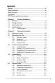
Contents Notices......................................................................................................... vii Safety information..................................................................................... viii About this guide.......................................................................................... ix Typography................................................................................................... x P7F-C Series specifications summary...................
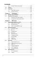
Contents 2.5.7 2.6 2.7 Connectors.................................................................................. 2-25 2.7.1 Rear panel connectors................................................... 2-25 2.7.2 Internal connectors........................................................ 2-26 Chapter 3: 3.1 3.2 4.2 4.3 4.4 iv Powering up Starting up for the first time......................................................... 3-3 Powering off the computer..............................................
Contents 4.5 4.4.3 Onboard Devices Configuration..................................... 4-22 4.4.4 USB Configuration......................................................... 4-24 4.4.5 PCIPnP.......................................................................... 4-25 4.4.6 ACPI Configuration........................................................ 4-26 4.4.7 Event Log Configuration................................................ 4-28 4.4.8 Intel VT-d Configuration [Disabled]....................
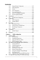
Contents 5.4 5.3.1 Integrated Mirroring........................................................ 5-15 5.3.2 Integrated Mirroring Enhanced...................................... 5-19 5.3.3 Integrated Striping (IS) volume...................................... 5-22 5.3.4 Managing Arrays............................................................ 5-25 5.3.5 Viewing SAS topology.................................................... 5-30 5.3.6 Global Properties............................................
Notices Federal Communications Commission Statement This device complies with Part 15 of the FCC Rules. Operation is subject to the following two conditions: • This device may not cause harmful interference, and • This device must accept any interference received including interference that may cause undesired operation. This equipment has been tested and found to comply with the limits for a Class B digital device, pursuant to Part 15 of the FCC Rules.
Safety information Electrical safety • To prevent electrical shock hazard, disconnect the power cable from the electrical outlet before relocating the system. • When adding or removing devices to or from the system, ensure that the power cables for the devices are unplugged before the signal cables are connected. If possible, disconnect all power cables from the existing system before you add a device.
About this guide This user guide contains the information you need when installing and configuring the motherboard. How this guide is organized This user guide contains the following parts: • Chapter 1: Product introduction This chapter describes the features of the motherboard and the new technologies it supports. • Chapter 2: Hardware information This chapter lists the hardware setup procedures that you have to perform when installing system components.
Conventions used in this guide To make sure that you perform certain tasks properly, take note of the following symbols used throughout this manual. DANGER/WARNING: Information to prevent injury to yourself when trying to complete a task. CAUTION: Information to prevent damage to the components when trying to complete a task. IMPORTANT: Instructions that you MUST follow to complete a task. NOTE: Tips and additional information to help you complete a task.
P7F-C Series specifications summary Model Name Processor / System Bus Core Logic Form Factor ASUS Features FAN speed control Rack Ready (Rack and Pedestal dual use) ASWM2.0 Memory Total Slots Capacity P7F-C/SAS P7F-C/4L 1 * Socket LGA1156 Quad Core Intel Xeon 3400 series Server Processor Quad Core Intel Core i7-800 series Desktop Processor Quad Core Intel Core i5-700 series Desktop Processor Dual Core 32nm CPU design Ready Dual Core/Quad Core Intel® 3420 PCH ATX, 12" * 9.
P7F-C Series specifications summary Onboard I/O Connectors Rear I/O Connectors Management Solution Monitoring Environment PSU Connector 24-pin ATX power connector + 8-pin ATX 12V power connector 24+4 pin power supply supported USB Connectors 3 (support 5 USB port) (One for internal Type A USB connector ) Fan Header 5* 4pin Chassis Intruder 1 1 Serial Port 1 1 Header External Serial 1 1 Port External USB 2 2 Port VGA Port 1 1 RJ-45 2 4 PS/2 KB/Mouse 1 1 Software ASWM2.0 ASWM2.
This chapter describes the motherboard features and the new technologies it supports.
Chapter summary 1 1.1 Welcome!....................................................................................... 1-3 1.3 Serial number label....................................................................... 1-4 1.2 1.4 Package contents.......................................................................... 1-3 Special features.............................................................................
1.1 Welcome! Thank you for buying an ASUS® P7F-C Series motherboard! The motherboard delivers a host of new features and latest technologies, making it another standout in the long line of ASUS quality motherboards! Before you start installing the motherboard, and hardware devices on it, check the items in your package with the list below. 1.2 Package contents Check your motherboard package for the following items.
1.3 Serial number label Before requesting support from the ASUS Technical Support team, you must take note of the motherboard's serial number containing 13 characters xxS2xxxxxxxxx shown as the figure below. With the correct serial number of the product, ASUS Technical Support team members can then offer a quicker and satisfying solution to your problems. P7F-C Series xxS2xxxxxxxxx 1.4 Special features 1.4.
DDR3 memory support The P7F-C Series supports UDIMM and RDIMM DDR3 memory that features data transfer rates of 1333/1066 MHZ to meet the higher bandwidth requirements of server and workstation applications. The 2-channel DDR3 architecture boosts system performance, eliminating bottlenecks. Furthermore, the supply voltage for the memory is reduced from 1.8 V for DDR2 to just 1.5V for DDR3. This voltage reduction limits the power consumption and heat generation of DDR3 which makes it an ideal memory solution.
USB 2.0 technology The motherboard implements the Universal Serial Bus (USB) 2.0 specification, dramatically increasing the connection speed from the 12 Mbps bandwidth on USB 1.1 to a fast 480 Mbps on USB 2.0. USB 2.0 is backward compatible with USB 1.1. Temperature, fan, and voltage monitoring The CPU temperature is monitored to prevent overheating and damage. The system fan rotations per minute (RPM) is monitored for timely failure detection.
This chapter lists the hardware setup procedures that you have to perform when installing system components. It includes description of the jumpers and connectors on the motherboard.
Chapter summary 2 2.1 Before you proceed...................................................................... 2-3 2.3 Central Processing Unit (CPU).................................................... 2-9 2.2 2.4 2.5 2.6 2.7 Motherboard overview.................................................................. 2-4 System memory.......................................................................... 2-15 Expansion slots...........................................................................
2.1 Before you proceed Take note of the following precautions before you install motherboard components or change any motherboard settings. • Unplug the power cord from the wall socket before touching any component. • Use a grounded wrist strap or touch a safely grounded object or a metal object, such as the power supply case, before handling components to avoid damaging them due to static electricity. • Hold components by the edges to avoid touching the ICs on them.
2.2 Motherboard overview Before you install the motherboard, study the configuration of your chassis to ensure that the motherboard fits into it. To optimize the motherboard features, we highly recommend that you install it in an ATX 1.1 compliant chassis. Ensure to unplug the chassis power cord before installing or removing the motherboard. Failure to do so can cause you physical injury and damage motherboard components! 2.2.
2.2.
P7F-C/4L 2-6 Chapter 2: Hardware information
2.2.4 Layout contents Slots/Soocket Page 1. CPU sockets 2-9 2. DDR3 sockets 2-15 3. PCI Express x 16 slot (x8 link) 2-19 4. PCI slots 2-19 Jumpers Page 1. Clear RTC RAM (CLRTC1) 2-21 2. VGA controller setting (3-pin VGA_SW1)) 2-22 3. CPU Fan and Chassis Fan control setting (3-pin CPUFAN_SEL1, CHAFAN_SEL1) 2-22 4. LAN controller setting (3-pin LAN_SW1, LAN_SW2) (LAN_SW3, LAN_SW4 P7F-C/4L Model only) 2-23 5.
Internal connectors 1. 2-8 Page Serial ATA connectors (7-pin SATA1, SATA2, SATA3, SATA4; RED) (7-pin SATA5, SATA6; Black) 2-26 2. Hard disk activity LED connector (4-pin HDLED1) 2-26 3. SAS connectors (7-pin SAS1, SAS2, SAS3, SAS4; RED) (7-pin SAS5, SAS6, SAS7, SAS8; Blue) (P7F-C/SAS model only) 2-27 4. USB connector (10-1 pin USB34, USB56; A-Type USB7) 2-27 5. Serial General Purpose Input/Output connector (6-1 pin SGPIO1) 2-28 6.
2.3 Central Processing Unit (CPU) The motherboard comes with a surface mount LGA1156 socket designed for the Intel® Xeon 3400 series Processors. 2.3.1 • Upon purchase of the motherboard, ensure that the PnP cap is on the socket and the socket contacts are not bent. Contact your retailer immediately if the PnP cap is missing, or if you see any damage to the PnP cap/socket contacts/motherboard components. ASUS will shoulder the cost of repair only if the damage is shipment/transit-related.
3. Lift the load lever in the direction of the arrow until the load plate is completely lifted. Load plate 4. Remove the PnP cap from the CPU socket. PnP cap Cap tab 5. Position the CPU over the socket, ensuring that the gold triangle is on the bottom‑left corner of the socket, and then fit the socket alignment keys into the CPU notches. The CPU fits in only one correct orientation.
6. Apply some Thermal Interface Material to the exposed area of the CPU that the heatsink will be in contact with, ensuring that it is spread in an even thin layer. Some heatsinks come with preapplied thermal paste. If so, skip this step. The Thermal Interface Material is toxic and inedible. DO NOT eat it. If it gets into your eyes or touches your skin, wash it off immediately, and seek professional medical help. 7.
2.3.2 Installing the CPU heatsink and fan The Intel LGA1156 processor requires a specially designed heatsink and fan assembly to ensure optimum thermal condition and performance. ® • When you buy a boxed Intel® processor, the package includes the CPU fan and heatsink assembly. If you buy a CPU separately, ensure that you use only Intel®‑certified multi‑directional heatsink and fan. • Your Intel® LGA1156 heatsink and fan assembly comes in a push-pin design and requires no tool to install.
3. Connect the CPU fan cable to the connector on the motherboard labeled CPU_FAN1. DO NOT forget to connect the CPU fan connector! Hardware monitoring errors can occur if you fail to plug this connector. 2.3.3 Uninstalling the CPU heatsink and fan A To uninstall the CPU heatsink and fan: 1. Disconnect the CPU fan cable from the connector on the motherboard. 2. Rotate each fastener counterclockwise. 3.
2.3.4 Installing the CPU heatsink in rack The Intel 1156 processors require a specially designed heatsink to ensure optimum thermal condition and performance. ® • Ensure that you use qualified heatsink assembly only. • Ensure that you have applied the thermal interface material to the top of the CPU before installing the heatsink. 1. Peel off the sticker on the heatsink metal plate and affix the plate to the back of the motherboard, matching the standoffs to the heatsink screw holes. 2.
2.4 System memory 2.4.1 Overview The motherboard comes with six Double Data Rate 3 (DDR3) Dual Inline Memory Modules (DIMM) sockets. A DDR3 module has the same physical dimensions as a DDR2 DIMM but is notched differently to prevent installation on a DDR2 DIMM socket. DDR3 modules are developed for better performance with less power consumption. The figure illustrates the location of the DDR3 DIMM sockets: 2.4.
2.4.3 Installing a DIMM Unplug the power supply before adding or removing DIMMs or other system components. Failure to do so can cause severe damage to both the motherboard and the components. 2 To install a DIMM: 1. Press the retaining clips outward to unlock a DIMM socket. 2. Align a DIMM on the socket such that the notch on the DIMM matches the break on the socket. 3. Firmly insert the DIMM into the socket until the retaining clips snap back in place and the DIMM is properly seated.
2.5 Expansion slots In the future, you may need to install expansion cards. The following subsections describe the slots and the expansion cards that they support. Ensure to unplug the power cord before adding or removing expansion cards. Failure to do so may cause you physical injury and damage motherboard components. 2.5.1 Installing an expansion card To install an expansion card: 1.
2.5.
2.5.4 PCI Express x16 slots (x8 link) The onboard PCI Express x16 slots provide x8 link to CPU. These slots support VGA cards and various server class high performance add-on cards. 2.5.5 PCI slots The PCI slot supports cards such as a LAN card, USB card, and other cards that comply with PCI 2.3 specifications.
2.5.6 Installing i Button Follow the steps below to install an optional i Button on your motherboard. 1. Locate the I Button slot on the motherboard. 2. Snap the I Button in place. 2.5.7 Connect Thermal sensor cable Follow the steps below to connect the thermal sensor cable to the connector on your motherboard. 2-20 1. Locate the TR1 connector on the motherboard. 2. Connect the thermal sensor cable to the connector. 3.
2.6 1. Jumpers Clear RTC RAM (CLRTC1) This jumper allows you to clear the Real Time Clock (RTC) RAM in CMOS. You can clear the CMOS memory of date, time, and system setup parameters by erasing the CMOS RTC RAM data. The onboard button cell battery powers the RAM data in CMOS, which include system setup information such as system passwords. To erase the RTC RAM: 1. Turn OFF the computer and unplug the power cord. 2. Move the jumper cap from pins 1–2 (default) to pins 2–3.
2. VGA controller setting (3-pin VGA_SW1) This jumper allows you to enable or disable the onboard VGA controller. Set to pins 1–2 to activate the VGA feature. 3. CPU Fan and Chassis Fan control setting (3-pin CPUFAN_SEL1, CHAFAN_SEL1) These jumpers allow you to switch for fan pin selection. The CPUFAN_SEL1 jumper is for the CPU fan control and the CHAFAN_SEL1 jumper is for the front fans and rear fans control. Set to pins 1–2 when using 4-pin fans or pins 2–3 when using 3-pin fans.
4. LAN controller setting (3-pin LAN_SW1, LAN_SW2) (LAN_SW3, LAN_SW4 P7F-C/4L model only ) These jumpers allow you to enable or disable the onboard Marvell® 88E8056 Gigabit LAN controllers. Set to pins 1��������������������������������������� –�������������������������������������� 2 to activate the Gigabit LAN feature. 3 4 5. RAID configuration utility selection (3-pin RAID_SEL1) (P7F-C/4L model only ) This jumper allows you to select the RAID configuration utility to use when you create disk arrays.
6. Onboard storage setting (3-pin SAS_SW1) (P7F-C/SAS model only) This jumper allows you to enable or disable the onboard LSI1068E SAS controller. Set the jumper to pins 1–2 to enable the SAS function (default). 7. Force BIOS recovery setting (3-pin RECOVERY1) This jumper allows you to quickly update or recover the BIOS settings when it becomes corrupted. To update the BIOS: 2-24 1. Set the jumper to pins 2–3. 2.
2.7 Connectors 2.7.1 Rear panel connectors 1. PS/2 mouse port (green). This port is for a PS/2 mouse. 3. USB 2.0 ports 1 and 2. These two 4-pin Universal Serial Bus (USB) ports are available for connecting USB 2.0 devices. 4. Serial (COM1) port. This 9-pin communication port is for pointing devices or other serial devices. 5. Video Graphics Adapter port. This port is for a VGA monitor or other VGAcompatible devices. 6. LAN 1 (RJ-45) port.
2.7.2 1. Internal connectors Serial ATA connectors (7-pin SATA1, SATA2, SATA3, SATA4; RED) (7-pin SATA5, SATA6; Black) Supported by the Intel® 3420 chipset, these connectors are for the Serial ATA signal cables for Serial ATA hard disk drives that allows up to 3Gb/s of data transfer rate. If you installed Serial ATA hard disk drives, you can create a RAID 0, RAID 1, RAID 10, or RAID 5 configuration. 2. • The actual data transfer rate depends on the speed of Serial ATA hard disks installed.
3. SAS connectors (7-pin SAS1, SAS2, SAS3, SAS4; Red) (7-pin SAS5, SAS6, SAS7, SAS8; Blue) (P7F-C/SAS model only) This motherboard comes with eight (8) Serial Attached SCSI (SAS) connectors, the next-generation storage technology that supports both Serial Attached SCSI (SAS) and Serial ATA (SATA). Each connector supports one device. 4. USB connector (10-1 pin USB34, USB56; A-Type USB7) These connectors are for USB 2.0 ports.
5. Serial General Purpose Input/Output connector (6-1 pin SGPIO1) This connector is used for the SGPIO peripherals for the LSI MegaRAID and Intel Matrix RAID SATA LED. 6. Serial General Purpose Input/Output connectors (8-1 pin SGPIO2/3) (P7F-C/SAS model only) These connector is used for the SAS chip SGPIO interface that controls the LED pattern generation, device information and general purpose data.
7. Serial port connector (10-1 pin COM2) This connector is for a serial (COM) port. Connect the serial port module cable to this connector, then install the module to a slot opening at the back of the system chassis. 8. CPU, front and rear fan connectors (4-pin CPU_FAN1, FRNT_FAN1, FRNT_FAN2, FRNT_FAN3, REAR_FAN1) The fan connectors support cooling fans of 350 mA–740 mA (8.88 W max.) or a total of 1.75 A–3.7 A (44.4 W max.) at +12V.
9. ATX power connectors (24-pin EATXPWR1, 8-pin EATX12V1) These connectors are for an ATX power supply plugs. The power supply plugs are designed to fit these connectors in only one orientation. Find the proper orientation and push down firmly until the connectors completely fit. 2-30 • DO NOT forget to connect the 24+8-pin power plugs; otherwise, the system will not boot up. • Use of a PSU with a higher power output is recommended when configuring a system with more power-consuming devices.
10. Thermal sensor cable connectors (3-pin TR1) This connector is for temperature monitoring. Connect the thermal sensor cable to this connector and place the other end to the device, which you want to monitor temperature. 11. Parallel port connector (26-1 pin LPT1) This connector is for a parallel port. Connect the parallel port module cable to this connector, then install the module to a slot opening at the back of the system chassis.
12. System panel connector (20-pin PANEL1) This connector supports several chassis-mounted functions. 2-32 1. System power LED (3-pin PLED) This 3-pin connector is for the system power LED. Connect the chassis power LED cable to this connector. The system power LED lights up when you turn on the system power, and blinks when the system is in sleep mode. 2. Message LED (2-pin MLED) This 2-pin connector is for the message LED cable that connects to the front message LED.
13. Auxiliary panel connector (20-pin AUX_PANEL1) This connector is for additional front panel features including front panel SMB, locator LED and switch, chassis intrusion, and LAN LEDs. 1. Front panel SMB (6-1 pin FPSMB) These leads connect the front panel SMBus cable. 2. LAN activity LED (2-pin LAN1_LED, LAN2_LED) These leads are for Gigabit LAN activity LEDs on the front panel. 3.
2-34 Chapter 2: Hardware information
This chapter describes the power up sequence, and ways of shutting down the system.
Chapter summary 3.1 3.2 3 Starting up for the first time......................................................... 3-3 Turning off the computer..............................................................
3.1 Starting up for the first time 1. After making all the connections, replace the system case cover. 2. Be sure that all switches are off. 3. Connect the power cord to the power connector at the back of the system chassis. 4. Connect the power cord to a power outlet that is equipped with a surge protector. 5. Turn on the devices in the following order: 6. a. Monitor b. External SCSI devices (starting with the last device on the chain) c.
3.2 Powering off the computer 3.2.1 Using the OS shut down function If you are using Windows® 2003 Server: 1. Click the Start button then click Shut Down. 2. Select Shut Down from the What do you want the computer to do? list box. 3. Select Shutdown Event Tracker. 4. Ensure that the Planned check box is checked. 5. Select shutdown option from the list box. 6. If necessary, key in comments. 7. Click OK. 3.2.
This chapter tells how to change the system settings through the BIOS Setup menus. Detailed descriptions of the BIOS parameters are also provided.
Chapter summary 4 4.1 Managing and updating your BIOS............................................. 4-1 4.3 Main menu................................................................................... 4-10 4.2 4.4 4.5 4.6 4.7 4.8 4.9 BIOS setup program..................................................................... 4-7 Advanced menu.......................................................................... 4-16 Server menu............................................................................
4.1 Managing and updating your BIOS The following utilities allow you to manage and update the motherboard Basic Input/Output System (BIOS) setup: 1. ASUS EZ Flash 2 (Updates the BIOS using a USB flash disk.) 2. BUPDATER utility (Updates the BIOS in DOS mode using a bootable USB flash disk drive.) 3. ASUS CrashFree BIOS 3 (To recover the BIOS using a bootable USB flash disk drive when the BIOS file fails or gets corrupted.) Refer to the corresponding sections for details on these utilities.
3. Press to switch between drives until the correct BIOS file is found. When found, EZ Flash 2 performs the BIOS update process and automatically reboots the system when done. • This function can support devices such as a USB flash disk with FAT 32/16 format and single partition only. • DO NOT shut down or reset the system while updating the BIOS to prevent system boot failure! Ensure to load the BIOS default settings to ensure system compatibility and stability.
4. The utility verifies the file, then starts updating the BIOS file. ASUSTek BIOS Update for DOS V1.06 (09/08/04) FLASH TYPE: MXIC 25L1605A Current ROM BOARD: P7F-C Series VER: 0205 DATE: 07/23/2009 Update ROM BOARD: P7F-C Series VER: 0206 DATE: 08/10/2009 PATH: WARNING! Do not turn off power during flash BIOS Note Writing BIOS: DO NOT shut down or reset the system while updating the BIOS to prevent system boot failure! 5.
4.1.3 ASUS CrashFree BIOS 3 utility The ASUS CrashFree BIOS 3 is an auto recovery tool that allows you to restore the BIOS file when it fails or gets corrupted during the updating process. You can update a corrupted BIOS file using a USB flash drive that contains the updated BIOS file. Prepare a USB flash drive containing the updated motherboard BIOS before using this utility. Recovering the BIOS from a USB flash drive To recover the BIOS from a USB flash drive: 1.
4.2 BIOS setup program This motherboard supports a programmable firmware chip that you can update using the provided utility described in section 4.1 Managing and updating your BIOS. Use the BIOS Setup program when you are installing a motherboard, reconfiguring your system, or prompted to “Run Setup.” This section explains how to configure your system using this utility. Even if you are not prompted to use the Setup program, you can change the configuration of your computer in the future.
4.2.1 BIOS menu screen Menu items Main Menu bar Advanced Configuration fields Server System Time System Date SATA SATA SATA SATA SATA SATA 1 2 3 4 5 6 : : : : : : BIOS SETUP UTILITY Power Boot Tools General help Exit [13:44:30] [Wed, 11/25/2009] Use [ENTER], [TAB] or [SHIFT-TAB] to select a field. [ST3160812AS] [Not Detected] [Not Detected] [Not Detected] [Not Detected] [Not Detected] Use [+] or [-] to configure system Date.
4.2.4 Menu items The highlighted item on the menu bar displays the specific items for that menu. For example, selecting Main shows the Main menu items. System Time System Date SATA1 SATA2 SATA3 SATA4 SATA5 SATA6 Detected] Detected] Detected] Detected] Detected] Detected] Use [ENTER], [TAB] or [SHIFT-TAB] to select a field. Use [+] or [-] to configure system Date.
4.3 Main menu When you enter the BIOS Setup program, the Main menu screen appears, giving you an overview of the basic system information. Refer to section 4.2.1 BIOS menu screen for information on the menu screen items and how to navigate through them. Main Advanced Server System Time System Date SATA SATA SATA SATA SATA SATA 1 2 3 4 5 6 : : : : : : BIOS SETUP UTILITY Power Boot Tools Exit [13:44:30] [Wed, 11/25/2009] Use [ENTER], [TAB] or [SHIFT-TAB] to select a field.
4.3.3 SATA1—6 While entering Setup, the BIOS automatically detects the presence of IDE/SATA devices. There is a separate submenu for each IDE/SATA device. Select a device item then press to display the SATA device information. BIOS SETUP UTILITY Main SATA1 Device :Hard Disk Vendor :xxxxxxxxx Size :xx.xGB LBA Mode :Supported Block Mode:16Sectors PIO Mode :4 Async DMA :MultiWord DMA-2 Ultra DMA :Ultra DMA-6 S.M.A.R.T.
DMA Mode [Auto] Sets the DMA mode. Configuration options: [Auto] [SWDMA0] [SWDMA1] [SWDMA2] [MWDMA0] [MWDMA1] [MWDMA2] [UDMA0] [UDMA1] [UDMA2] [UDMA3] [UDMA4] [UDMA5] SMART Monitoring [Auto] Sets the Smart Monitoring, Analysis, and Reporting Technology. Configuration options: [Auto] [Disabled] [Enabled] 32Bit Data Transfer [Enabled] Enables or disables 32-bit data transfer.
4.3.4 Storage Configuration The items in this menu allow you to set or change the configurations for the IDE/SATA devices installed in the system. Select an item then press if you wish to configure the item.
4.3.5 AHCI Configuration This menu is the section for AHCI configuration. It appears only when you set the item Configure SATA as from the sub-menu of SATA Configuration to [AHCI]. BIOS SETUP UTILITY Main AHCI Settings SATA SATA SATA SATA SATA SATA Port1 Port2 Port3 Port4 Port5 Port6 [Not [Not [Not [Not [Not [Not Some SATA CD/DVD in AHCI mode need to wait ready longer.
4.3.6 System Information This menu gives you an overview of the general system specifications. The BIOS automatically detects the items in this menu. BIOS SETUP UTILITY Main BIOS Information BIOS Version :0201 BIOS Build Date :11/13/09 Processor Type Speed :Intel(R) Xeon(R) CPU 2.53GHz :2533MHz System Memory Usable Size X3440 @ : 2040MB ←→ ↑↓ Enter F1 F10 ESC System Memory Information Select Screen Select Item Go to Sub Screen General Help Save and Exit Exit v02.
4.4 Advanced menu The Advanced menu items allow you to change the settings for the CPU and other system devices. Take caution when changing the settings of the Advanced menu items. Incorrect field values can cause the system to malfunction. Main Advanced BIOS SETUP UTILITY Power Boot Tools Server Exit Configure CPU.
Scroll down for more items. Advanced BIOS SETUP UTILITY Execute-Disable Bit Capability Intel(R) HT Technology Active Processor Cores A20M Intel(R) SpeedStep(TM) Tech Intel(R) TurboMode Tech Intel(R) C-STATE Tech C3 State C6 State C State package limit setting C1 Auto Demotion C3 Auto Demotion [Enabled] [Enabled] [All] [Disabled] [Enabled] [Enabled] [Enabled] [ACPI C2] [Enabled] [Auto] [Enabled] [Enabled] Sets the ratio between CPU Core Clock and the FSB Frequency.
Execute-Disable Bit Capability [Enabled] Allows you to enable or disable the No-Execution Page Protection Technology. Setting this item to [Disabled] forces the XD feature flag to always return to zero (0). Configuration options: [Disabled] [Enabled] Intel(R) HT Technology [Enabled] Allows you to enable or disable the Intel Hyper-Threading Technology function. When disabled, only one thread per activated core is enabled.
C State package limit setting [Auto] We recommend that you set this item to [Auto] for BIOS to automatically detect the C-State mode supported by your CPU. Configuration options: [Auto] [C1] [C3] [C6] C1 Auto Demotion [Enabled] When this item is enabled, the CPU will conditionally demote C3/C6/C7 requests to C1 based on the uncore auto-demote information.
4.4.2 Chipset The Chipset configuration menu allows you to change advanced chipset settings. Select an item then press to display the sub-menu. Advanced BIOS SETUP UTILITY Advanced Chipset Settings Configure CPU Bridge features. WARNING: Setting wrong values in below sections may cause system to malfunction. Uncore Configuration ←→ ↑↓ Enter F1 F10 ESC Select Screen Select Item Go to Sub Screen General Help Save and Exit Exit v02.61 (C)Copyright 1985-2008, American Megatrends, Inc.
Configure DRAM Timing by SPD [Enabled] Configuration options: [Enabled] [Disabled] The ofllowing 10 items appear when you set Configure DRAM Timing by SPD to [Disabled].
Double Rate Refresh [Auto] Allows you to enable or disable Double Rate Refresh. Configuration options: [Auto] [Disabled] Page Poilcy [Closed] Configuration options: [Closed] [Open] Adaptive Page [Disabled] Configuration options: [Disabled] [Enabled] Data Scramble [Disabled] Configuration options: [Disabled] [Enabled] Memory Thermal Throttling [Disabled] Setting this item to [CLTT] to Closed Loop Thermal Throttling and [OLTT] to Open Loop Thermal Throttling.
Onboard LAN1/2/3/4 Boot ROM [PXE] Allows you to configure the onboard LAN1/2/3/4 boot mode. Configuration: [Disabled] [PXE] Onboard LAN3/4 Boot ROM are available only for P7F-C/4L model. LSI 1068E Boot ROM [Enabled] Allows you to configure the onboard LSI 1068E boot mode. Configuration: [Enabled] [Disabled] LSI 1068E Boot ROM is available only for P7F-C/SAS model. Serial Port1 Address [3F8/IRQ4] Allows you to select the Serial Port1 base address.
4.4.4 USB Configuration Advanced BIOS SETUP UTILITY USB Configuration Options Module Version - 2.24.5-13.4 Disabled Enabled USB Devices Enabled: 2 Hubs USB Functions Legacy USB Support BIOS EHCI Hand-off [Enabled] [Auto] [Enabled] ←→ ↑↓ +F1 F10 ESC Select Screen Select Item Change Option General Help Save and Exit Exit v02.61 (C)Copyright 1985-2008, American Megatrends, Inc. USB Functions [Enabled] Allows you to enabled or disable the USB function.
4.4.5 PCIPnP The PCIPnP menu items allow you to change the advanced settings for PCI/PnP devices. Take caution when changing the settings of the PCI/PnP Configuration menu items. Incorrect field values can cause the system to malfunction. Advanced BIOS SETUP UTILITY Advanced PCI/PnP Settings WARNING: Setting wrong values in below sections may cause system to malfunction.
4.4.6 ACPI Configuration BIOS SETUP UTILITY Advanced ACPI Settings Advanced ACPI Configuration settings. Advanced ACPI Configuration Chipset ACPI Configuration General WHEA Configuration Use this section to configure additional ACPI options. ←→ ↑↓ +F1 F10 ESC Select Screen Select Item Change Option General Help Save and Exit Exit v02.61 (C)Copyright 1985-2009, American Megatrends, Inc.
Chipset ACPI Configuration Advanced BIOS SETUP UTILITY South Bridge ACPI Configuration Energy Lake Feature APIC ACPI SCI IRQ High Performance Event Timer HPET Memory Address Options [Disabled] [Disabled] [Enabled] [FED00000h] Enabled Disabled Energy Lake Feature [Disabled] Allows you to enable or disable the Energy Lake feature. Configuration options: [Enabled] [Disabled] We do not recommend you enable this feature.
4.4.7 Event Log Configuration Main Advanced BIOS SETUP UTILITY Event Logging details View all unread events on the Event Log. View Event Log Mark all event as read Clear Event Log View Event Log Press to read all the unread event log. Mark all events as read Press to mark all the events as read. Clear Event Log Press to clear all events on the event log. 4.4.
4.5 Main Server menu Advanced BIOS SETUP UTILITY Power Boot Tools Server Exit Configure Remote Access. Remote Access Configuration ←→ ↑↓ +F1 F10 ESC Select Screen Select Item Change Option General Help Save and Exit Exit v02.61 (C)Copyright 1985-2009, American Megatrends, Inc. 4.5.1 Remote Access Configuration The items in this menu allows you to configure the Remote Access features. Select an item then press to display the configuration options.
Serial port number [COM2] Selects the serial port for console redirection. Configuration options: [COM1] [COM2] Base Address. IRQ [2F8h, 3] This item is not user-configurable and changes with the configuration of Serial port number. Serial Port Mode [57600 8,n,1] Sets the Serial port mode. Configuration options: [115200 8,n,1] [57600 8,n,1] [38400 8,n,1] [19200 8,n,1] [09600 8,n,1] Flow Control [Hardware] Allows you to select the flow control for console redirection.
4.6 Main Power menu Advanced Server BIOS SETUP UTILITY Power Boot Tools Exit Include ACPI APIC table pointer to RSDT pointer list. APM Configuration Hardware Monitor ←→ ↑↓ +F1 F10 ESC Select Screen Select Item Change Option General Help Save and Exit Exit v02.61 (C)Copyright 1985-2009, American Megatrends, Inc. 4.6.
Power On By RTC Alarm [Disabled] Allows you to enable or disable RTC to generate a wake-up event. Configuration options: [Disabled] [Enabled] The following items appear only when the Resume On RTC Alarm item is set to [Enabled]. RTC Alarm Date [15] To set the alarm date, highlight this item and press the <+> or <-> key to make the selection. System Time [12:30:30] Use the , or key to select a field. Use the <+> or <-> key to configure alarm time.
4.6.2 Hardware Monitor BIOS SETUP UTILITY Power Hardware Monitor CPU Temperature(PECI) MB Temperature TR1 Temperature CPU Fan1 Speed FRNT FAN1 Speed FRNT FAN2 Speed FRNT FAN3 Speed REAR FAN1 Speed FAN Speed Control VCORE1 3.3V Voltage 5V Voltage 12V Voltage VBAT Voltage 3VSB Voltage 1.5V ICH Voltage [ 35ºC/ 94ºF] [ 30ºC/ 86ºF] [ N/A ] [ 5357RPM] [ N/A ] [ N/A ] [ N/A ] [ N/A ] [Generic Mode] [ 1.052 V] [ 3.246 V] [ 5.196 V] [12.000 V] [ 3.126 V] [ 3.198 V] [ 1.
4.7 Boot menu The Boot menu items allow you to change the system boot options. Select an item then press to display the sub-menu. Main Advanced BIOS SETUP UTILITY Power Boot Tools Server Exit Specifies the Boot Device Priority sequence. Boot Settings Boot Device Priority A virtual floppy disk drive (Floppy Drive B: ) may appear when you set the CD-ROM drive as the first boot device.
4.7.3 Boot Settings Configuration BIOS SETUP UTILITY Boot Boot Settings Configuration Quick Boot Full Screen Logo AddOn ROM Display Mode Bootup Num-Lock Wait For ‘F1‘ If Error Hit ‘DEL‘ Message Display [Enabled] [Enabled] [Force BIOS] [On] [Enabled] [Enabled] Allows BIOS to skip certain tests while booting. This will decrease the time needed to boot the system. ←→ ↑↓ +F1 F10 ESC Select Screen Select Item Change Option General Help Save and Exit Exit v02.
4.7.4 Security The Security menu items allow you to change the system security settings. Select an item then press to display the configuration options. BIOS SETUP UTILITY Boot Security Settings Supervisor Password : Not Installed User Password : Not Installed to change password. again to disable password. Change Supervisor Password Change User Password ←→ ↑↓ Enter F1 F10 ESC Select Screen Select Item Change General Help Save and Exit Exit v02.
After you have set a supervisor password, the other items appear to allow you to change other security settings. Main Advanced Server BIOS SETUP UTILITY Power Boot Tools Supervisor Password : Installed User Password : Not Installed Change Supervisor Password User Access Level Change User Password Password Check [Full Access] Exit to change password. again to disable password.
4.8 Tools menu The Tools menu items allow you to configure options for special functions. Select an item then press to display the submenu. Main Advanced Server BIOS SETUP UTILITY Power Boot Tools ASUS EZ Flash 2 Exit Press ENTER to run the utility to select and update BIOS. This uitlity supports 1. FAT 12/16/32 (r/w) 2. NTFS (read only) 3. CD-DISC (read only) ←→ ↑↓ Enter F1 F10 ESC Select Screen Select Item Go to Sub Screen General Help Save and Exit Exit v02.
4.9 Exit menu The Exit menu items allow you to load the optimal or failsafe default values for the BIOS items, and save or discard your changes to the BIOS items. Main Advanced Server Exit Options Exit & Save Changes Exit & Discard Changes Discard Changes BIOS SETUP UTILITY Power Boot Tools Exit Exit system setup after saving the changes. F10 key can be used for this operation.
4-40 Chapter 4: BIOS setup
This chapter provides instructions for setting up, creating, and configuring RAID sets using the available utilities.
Chapter summary 5 5.1 Setting up RAID............................................................................. 5-3 5.3 LSI Logic MPT Setup Utility (P7F-C/SAS model only) ............. 5-15 5.2 5.4 Intel® Matrix Storage Manager Option ROM Utility.................... 5-5 LSI Software RAID Configuration Utility (P7F-C/4L model only) ................................................................
5.1 Setting up RAID The motherboard supports the following SATA RAID solutions: • Intel Matrix Storage Manager with RAID 0, RAID 1, RAID 10, and RAID 5 support (for Windows OS only). • LSI1068E PCI-E SAS controller (P7F-C/SAS model only) supports SAS disk drives and RAID0, RAID1, and RAID1E configuration. • LSI MegaRAID software RAID Configuration Utility (P7F-C/4L model only) with RAID 0, RAID 1, and RAID 10 support (for both Linux and Windows OS). 5.1.
5.1.2 Installing hard disk drives The motherboard supports Serial ATA for RAID set configuration. For optimal performance, install identical drives of the same model and capacity when creating a disk array. To install the SATA hard disks for RAID configuration: 1. Install the SATA hard disks into the drive bays following the instructions in the system user guide. 2. Connect a SATA signal cable to the signal connector at the back of each drive and to the SATA connector on the motherboard. 3.
5.2 Intel® Matrix Storage Manager Option ROM Utility The Intel® Matrix Storage Manager Option ROM utility allows you to create RAID 0, RAID 1, RAID 10 (RAID 1+0), and RAID 5 set(s) from Serial ATA hard disk drives that are connected to the Serial ATA connectors supported by the PCH. To enter the Intel® Matrix Storage Manager option ROM utility: 1. Install all the Serial ATA hard disk drives. 2. Turn on the system. 3. During POST, press to display the utility main menu.
5.2.1 Creating a RAID set To create a RAID set 1. From the utility main menu, select 1. Create RAID Volume and press . The following screen appears. Intel(R) Matrix Storage Manager option ROM v8.9.0.1023 PCH-D wRAID5 Copyright(C) 2003-09 Intel Corporation. All Rights Reserved. [ CREATE VOLUME MENU ] Name: RAID Level: Disks: Strip Size: Capacity: Sync: Volume0 RAID0(Stripe) Select Disks 128KB 0.
6. Use the up/down arrow key to select the stripe size for the RAID array (for RAID 0, 10 and 5 only), and then press . The available stripe size values range from 4 KB to 128 KB. The following are typical values: RAID 0: 128KB RAID 10: 64KB RAID 5: 64KB We recommend a lower stripe size for server systems, and a higher stripe size for multimedia computer systems used mainly for audio and video editing. 7.
2. Enter a name for the recovery set and press . 3. When the RAID Level item is selected, press the up/down arrow key to select Recovery, and then press . 4. When the Disks item is selected, press to select the hard disk drives you want to include in the recovery set. The SELECT DISKS screen appears. [ SELECT DISKS ] Port 0 1 2 3 Drive Model ST3160812AS ST3160812AS ST3160812AS ST3160812AS Serial # 9LS0HJA4 9LS0F4HL 3LS0JYL8 9LS0BJ5H Size 149.0GB 149.0GB 149.0GB 149.
5.2.3 Deleting a RAID set Take caution when deleting a RAID set. You will lose all data on the hard disk drives when you delete a RAID set. To delete a RAID set 1. From the utility main menu, select 2. Delete RAID Volume and press . The following screen appears. Intel(R) Matrix Storage Manager option ROM v8.9.0.1023 PCH-D wRAID5 Copyright(C) 2003-09 Intel Corporation. All Rights Reserved. [ DELETE VOLUME MENU ] Name Volume0 Level RAID0(Stripe) Drives 2 Capacity 298.
5.2.4 Resetting disks to Non-RAID Take caution before you reset a RAID volume hard disk drive to non-RAID. Resetting a RAID volume hard disk drive deletes all internal RAID structure on the drive. To reset a RAID set hard disk drive 1. From the utility main menu, select 3. Reset Disks to Non-RAID and press . The following screen appears. [ RESET RAID DATA ] Resetting RAID disk will remove its RAID structures and revert it to a non-RAID disk.
5.2.5 Recovery Volume Options If you have created a recovery set, you can configure more recovery set options following the descriptions in the section. See section 5.3.2 Creating a Recovery set to create a recovery set before continue. To configure a recovery set 1. From the utility main menu, select 4. Recovery Volume Options and press . The following screen appears. Intel(R) Matrix Storage Manager option ROM v8.9.0.1023 PCH-D wRAID5 Copyright(C) 2003-09 Intel Corporation. All Rights Reserved.
5.2.6 Exiting the Intel® Matrix Storage Manager To exit the utility 1. From the utility main menu, select 5. Exit, and then press . The following warning message appears. [ CONFIRM EXIT ] Are you sure you want to exit? (Y/N): 2. Press to exit or press to return to the utility main menu. 5.2.7 Rebuilding the RAID This option is only for the RAID 1 set.
3. The utility immediately starts rebuilding after the disk is selected. The status of the degraded RAID volume is changed to “Rebuild”. Intel(R) Matrix Storage Manager option ROM v8.9.0.1023 PCH-D wRAID5 Copyright(C) 2003-09 Intel Corporation. All Rights Reserved. [ MAIN MENU ] 1. Create RAID Volume 2. Delete RAID Volume 3. Reset Disks to Non-RAID 4. Recovery Volume Options 5.
5.2.8 Setting the Boot array in the BIOS Setup Utility You can set the boot priority sequence in the BIOS for your RAID arrays when creating multi-RAID using the Intel® Matrix Storage Manager. To set the boot array in the BIOS: Set at least one of the arrays bootable to boot from the hard disk. 1. Reboot the system and press to enter the BIOS setup utility during POST. 2. Go to the Boot menu and select the option Boot Device Priority. 3.
5.3 LSI Logic MPT Setup Utility (P7F-C/SAS model only) The LSI Logic MPT Setup Utility is an integrated RAID solution that allows you to allows you to create the following RAID set(s) from SAS hard disk drives supported by the LSI1068E SAS controller: • RAID 1 (Integrated Mirroring) • RAID 1E (Integrated Mirroring Enhanced) • RAID 0 (Integrated Striping) 5.3.1 Integrated Mirroring Overview The Integrated Mirroring (IM) feature supports simultaneous mirrored volumes with two disks (IM).
3. The following screen appears. Select a channel and press to enter the setup. LSI Logic Config Utility v6.16.00.00 (2007.05.07) Adapter List Global Properties Adapter PCI PCI PCI PCI FW Revision Status BUS Dev Fnc Slot SAS1068E 04 03 00 00 1.22.01.00-IR Enabled Esc = Exit Menu F1/Shift+1 = Help Alt+N = Global Properties -/+ = Alter Boot Order Boot Order 0 Ins/Del = Alter Boot List The numbers of the channel depend on the controller. 4. The Adapter Properties screen appears.
5. The Select New Array Type screen appears. Use the arrow keys to select Create IM Volume, then press . LSI Logic Config Utility v6.16.00.00 (2007.05.07) Select New Array Type -- SAS1068E Create IM Volume Create Integrated Mirror Array of 2 disks plus up to 2 optional hot spares. Data on the primary disk may be migrated. Create IME Volume Create Integrated Mirrored Enhanced Array of 3 to 10 disks including up to 2 optional hot spares.
7. A confirmation screen appears. Press to keep existing data on the first disk. If you choose this option, data on the first disk will be mirrored on the second disk that you will add to the volume later. Make sure the data you want to mirror is on the first disk. Press to overwrite any data and create the new IM array. LSI Logic Config Utility v6.16.00.00 (2007.05.07) Create New Array Type -- SAS1068E M - Keep existing data, migrate to an IM array. Synchronization of disk will occur.
5.3.2 Integrated Mirroring Enhanced To create an IME volume: 1. The Adapter Properties screen appears. Use the arrow keys to select RAID Properties, then press . LSI Logic Config Utility Adapter Properties -- SAS1068E v6.16.00.00 (2007.05.07) Adapter PCI Slot PCI Address(Bus/Dev/Func) MPT Firmware Revision SAS Address NVDATA Version Status Boot Order Boot Support SAS1068E 00 04:00:00 1.22.01.00-IR 500E0101:23456712 2B.
3. The Create New Array screen shows the disks you can add to make up the IME volume. Integrated Mirroring Enhanced (IME) supports three to ten disks, or seven mirrored disks plus two hot spare disks. Use the arrow key to select a disk, then move the cursor to the RAID Disk column. To include this disk in the array, press <+>, <->, or . You may also specify the Hot Spare disk here. Select the disk, then move the cursor to the Hot Spr column, then press <+>, <->, or .
4. Repeat step 5 to add the other disks to the volume. 5. When done, press to create the array, then select Save changes then exit this menu. Create and save new array? Cancel Exit Save changes then exit this menu Discard changes then exit this menu Exit the Configuration Utility and Reboot 6. The utility creates the array. LSI Logic Config Utility v6.16.00.00 (2007.05.07) Processing...
5.3.3 Integrated Striping (IS) volume Overview The Integrated Striping (IS) feature provides RAID 0 functionality, supporting volumes with two to eight disks. You may combine an IS volume with an IM or IME volume. Creating Integrated Striping volumes DO NOT combine Serial ATA and SAS disk drives in one volume. To create an IS volume: 1. Turn on the system after installing all SAS hard disk drives. 2. During POST, press to enter the SAS configuration utility. LSI Logic Corp.
4. The Select New Array Type screen appears. Use the arrow keys to select Create IS Volume, then press . LSI Logic Config Utility Select New Array Type -- SAS1068E v6.16.00.00 (2007.05.07) Create IM Volume Create Integrated Mirror Array of 2 disks plus up to 2 optional hot spares. Data on the primary disk may be migrated. Create IME Volume Create Integrated Mirrored Enhanced Array of 3 to 10 disks including up to 2 optional hot spares.
6. Repeat step 5 to add the other disks to the volume. 7. When done, press to create the array, then select Save changes then exit this menu. Create and save new array? Cancel Exit Save changes then exit this menu Discard changes then exit this menu Exit the Configuration Utility and Reboot 9. The utility creates the array. LSI Logic Config Utility v6.16.00.00 (2007.05.07) Processing...
5.3.4 Managing Arrays The LSI Logic MPT Setup Utility allows you to perform other tasks related to configuring and maintaining IM and IME volumes. Refer to this section to view volume properties, manage the hot spare disk, synchronize the array, activate the array, and delete the array. Viewing volume properties To view volume properties: 1. On the main menu, select RAID Properties. LSI Logic Config Utility Adapter Properties -- SAS1068E v6.16.00.00 (2007.05.
3. The View Existing Array screen appears. Here you can view properties of the RAID array(s) created. If you have configured a hot spare, it will also be listed. if you created more than one array, you may view the next array by pressing . LSI Logic Config Utility View Array -- SAS1068E Array Identifier Type Scan Order Size(MB) Status v6.16.00.00 (2007.05.
Managing hot spares You may configure one disk as a global hot spare to protect critical data on the IM/ IME volume(s). You may create the hot spare disk at the same time you create the IM/IME volume. Refer to this section when adding a hot spare disk on an existing volume. If a disk on an IM/IME volume fails, the utility automatically rebuilds the failed disk data on the hot spare. When the failed disk is replaced, the utility assigns the replacement as the new hot spare. To create a hot spare: 1. 2.
4. Use the arrow key to select the disk you would like to configure as hot spare, then move the cursor to the Hot Spr column. Press <+>, <->, or . The Drive Status column field now shows Hot Spare. Press to commit the changes. LSI Logic Config Utility Manage Hot Spare -- SAS1068E Identifier Type Scan Order Size(MB) Status Slot Num 0 1 2 3 v6.16.00.00 (2007.05.
Activating an array If an array is removed from one controller/computer or moved to another, the array is considered inactive. When you add the array back to the system, you may reactivate the array. To activate the array: 1. From the Manage Array screen, select Activate Array, then press . LSI Logic Config Utility Manage Array -- SAS1068E Identifier Type Scan Order Size(MB) Status v6.16.00.00 (2007.05.
5.3.5 1. Viewing SAS topology From the Adapter Properties screen, select SAS Topology. LSI Logic Config Utility Adapter Properties -- SAS1068E v6.16.00.00 (2007.05.07) Adapter PCI Slot PCI Address(Bus/Dev/Func) MPT Firmware Revision SAS Address NVDATA Version Status Boot Order Boot Support RAID Properties SAS1068E 00 04:00:00 1.22.01.00-IR 500E0101:23456712 2B.
5.3.6 Global Properties From the Setup Utility screen, press to enter LSI Logic Configuration, then select Global Properties. The Global Properties menu allows you to change related settings. LSI Logic Config Utility Adapter List Global Properties Adapter SAS1068E PCI BUS 04 PCI Dev 03 PCI Fnc 00 v6.16.00.00 (2007.05.07) PCI FW Revision Slot 00 1.22.01.
Boot Information Display Mode Sets the disk information display mode. Configuration options: [Display adapters & installed devices] [Display adapters only] [Display adapters and all devices] [Display minimal information] LSI Logic Config Utility Adapter List Global Properties Pause When Boot Alert Displayed Boot Information Display Mode Support Interrupt v6.16.00.00 (2007.05.
Restore Defaults This option allows you to discard the selections you made and restore the system defaults. LSI Logic Config Utility Adapter List Global Properties Pause When Boot Alert Displayed Boot Information Display Mode Support Interrupt v6.16.00.00 (2007.05.
5.4 LSI Software RAID Configuration Utility (P7F-C/4L model only) The LSI MegaRAID software RAID configuration utility allows you to create RAID 0, RAID 1, or RAID 10 set(s) from SATA hard disk drives connected to the SATA connectors supported by the motherboard southbridge chip. To enter the LSI MegaRAID software RAID configuration utility 1. Turn on the system after installing all the SATA hard disk drives. 2.
Menu Description Configure Allows you to create RAID 0, RAID 1 or RAID 10 set using the Easy Configuration or the New Configuration command.
2. The ARRAY SELECTION MENU displays the available drives connected to the SATA ports. Use the up/down arrow key to select the drives you want to include in the RAID set, and then press . When selected, the drive indicator changes from READY to ONLIN A[X]-[Y], where X is the array number, and Y is the drive number. LSI Software RAID Configuration Utility Ver A.62 Apr 29, 2009 BIOS Version A.09.
5. Press again, the virtual drive information appears including a Virtual Drive menu that allows you to change the virtual drive parameters. LSI Software RAID Configuration Utility Ver A.62 Apr 29, 2009 BIOS Virtual VersionDrive(s) A.09.
8. When creating a RAID 1 or a RAID 10 set, select DWC from the Virtual Drive menu, and then press . When creating a RAID 0 set, proceed to step 10. 9. Select On to enable the Disk Write Cache setting, and then press . LSI Software RAID Configuration Utility Ver A.62 Apr 29, 2009 BIOSVirtual VersionDrive(s) A.09.
11. Follow step 2 to 10 to configure additional virtual drives. 12. Press to finish RAID configuration. When prompted to save configuration, select Yes from the menu, and then press . LSI Software RAID Configuration Utility Ver A.62 Apr 29, 2009 BIOS Version A.09.
2. Follow step 2 to 7 of the previous section: Using Easy Configuration. 3. Select Size from the Virtual Drive menu, and then press . 4. Key-in the desired virtual drive size, and then press . LSI Software RAID Configuration Utility Ver A.62 Apr 29, 2009 BIOS Virtual VersionDrive(s) A.09.
5.4.2 Adding or viewing a RAID configuration You can add a new RAID configuration or view an existing configuration using the View/Add Configuration command. Adding a new RAID configuration To add a new RAID configuration: 1. From the Management Menu, select Configure > View/Add Configuration, and then press . LSI Software RAID Configuration Utility Ver A.62 Apr 29, 2009 BIOS Version A.09.
5.4.3 Initializing the virtual drives After creating the RAID set(s), you must initialize the virtual drives. You may initialize the virtual drives of a RAID set(s) using the Initialize or Objects command on the Management Menu. Using the Initialize command To initialize the virtual drive using the Initialize command 1. From the Management Menu, select Initialize, and then press . LSI Software RAID Configuration Utility Ver A.62 Apr 29, 2009 BIOS Version A.09.
3. Press to start initialization. When prompted, select Yes from the Initialize? dialog box, and then press . LSI Software RAID Configuration Utility Ver A.62 Apr 29, 2009 BIOS Version A.09.
Using the Objects command To initialize the virtual drives using the Objects command 1. From the Management Menu, select Objects > Virtual Drive, and then press . LSI Software RAID Configuration Utility Ver A.62 Apr 29, 2009 BIOS Version A.09.04300936R Objects Management Menu Adapter Configure Virtual Drive Initialize Physical Drive Objects Rebuild Check Consistency Change VD Parameters Use Cursor Keys To Navigate Between Items And Press Enter To Select An Option 2.
3. Select Initialize from the pop-up menu, and then press to start initialization. LSI Software RAID Configuration Utility Ver A.62 Apr 29, 2009 BIOS Version A.09.04300936R Vitual Drive(1) Virtual Drive 0 Objects Management Menu Adapter Configure Virtual Drive Initialize Physical Drive Objects Vitual Drive(0) Rebuild Initialze Check Consistency Check Consistency View/Update Parameters Initilize VD Use Cursor Keys To Navigate Between Items And Press Enter To Select An Option 4.
5.4.4 Rebuilding failed drives You can manually rebuild failed hard disk drives using the Rebuild command in the Management Menu. To rebuild a failed hard disk drive 1. From the Management Menu, select Rebuild, and then press . LSI Software RAID Configuration Utility Ver A.62 Apr 29, 2009 BIOS Version A.09.04300936R Management Menu Configure Initialize Objects Rebuild Check Consistency Rebuild PD(s) Use Cursor Keys To Navigate Between Items And Press Enter To Select An Option 2.
3. After selecting the drive to rebuild, press . When prompted, press to rebuild the drive. LSI Software RAID Configuration Utility Ver A.62 Apr 29, 2009 BIOS Version A.09.04300936R REBUILD - PHYSICAL DRIVES SELECTION MENU Management Menu PORT # Configure 0 ONLIN A00-00 Initialize Objects 1 RBLD A00-01 Rebuild Check Consistency Rebuilding Of Drive Will Take A Few Minutes.
5.4.5 Checking the drives for data consistency You can check and verify the accuracy of data redundancy in the selected virtual drive. The utility can automatically detect and/or detect and correct any differences in data redundancy depending on the selected option in the Objects > Adapter menu. The Check Consistency command is available only for virtual drives included in a RAID 1 or RAID 10 set. Using the Check Consistency Command To check data consistency using the Check Consistency command 1.
3. When prompted, use the arrow keys to select Yes from the Consistency Check? dialog box, and then press . LSI Software RAID Configuration Utility Ver A.62 Apr 29, 2009 BIOS Version A.09.
Using the Objects command To check data consistency using the Objects command 5-50 1. From the Management Menu, select Objects, and then select Virtual Drive from the sub-menu. 2. Use the arrow keys to select the virtual drive you want to check, and then press . 3. Select Check Consistency from the pop-up menu, and then press . 4. When prompted, use the arrow keys to select Yes from the dialog box to check the drive. 5. When checking is complete, press any key to continue.
5.4.6 Deleting a RAID configuration To delete a RAID configuration 1. From the Management Menu, select Configure > Clear Configuration, and then press . LSI Software RAID Configuration Utility Ver A.62 Apr 29, 2009 BIOS Version A.09.
5.4.7 Selecting the boot drive from a RAID set You must have created a new RAID configuration before you can select the boot drive from a RAID set. See section 5.2.1 Creating a RAID set: Using New Configuration for details. To select the boot drive from a RAID set 1. From the Management Menu, select Configure > Select Boot Drive, and then press . LSI Software RAID Configuration Utility Ver A.62 Apr 29, 2009 BIOS Version A.09.
5.4.8 Enabling WriteCache You may manually enable the RAID controller’s WriteCache option after creating a RAID set to improve the data transmission performance. When you enable WriteCache, you may lose data when a power interruption occurs while transmitting or exchanging data among the drives. The WriteCache function is recommended for RAID 1 and RAID 10 sets. To enable WriteCache 1. From the Management Menu, select Objects > Adapter, and then press to display the adapter properties. 2.
5-54 Chapter 5: RAID configuration
This chapter provides instructions for installing the necessary drivers for different system components.
Chapter summary 6 6.1 RAID driver installation................................................................ 6-3 6.3 LAN driver installation................................................................ 6-21 6.2 6.4 6.5 Intel chipset device software installation................................. 6-19 VGA driver installation............................................................... 6-23 Management application and utilities installation...................
6.1 RAID driver installation After creating the RAID sets for your server system, you are now ready to install an operating system to the independent hard disk drive or bootable array. This part provides instructions on how to install the RAID controller drivers during OS installation. 6.1.1 Creating a RAID driver disk The system does not include a floppy drive. You have to use a USB floppy drive when creating a SATA RAID driver disk.
PCH LSI RAID Driver PCH LSI RAID Driver Windows XP 32 bit Windows XP 64 bit Windows Server 2003 32 Windows Server 2003 64 Windows Vista 32 bit Windows Vista 64 bit Windows Server 2008 32 Windows Server 2008 64 RHEL AS4 UP5 32/64 bit RHEL AS4 UP6 32/64 bit RHEL AS4 UP7 32/64 bit RHEL AS4 UP8 32/64 bit RHEL 5 32/64 bit RHEL 5 UP1 32/64 bit RHEL 5 UP2 32/64 bit RHEL 5 UP3 32/64 bit SLES 9 SP3 32 bit SLES 9 SP3 64 bit SLES 9 SP4 32 bit SLES 9 SP4 64 bit SLES 10 32 bit SLES 10 64 bit bit bit bit bit LSI 1068E
6. Locate the RAID driver and place a blank, high-density floppy disk to the floppy disk drive. 7. Press . 8. Follow screen instructions to create the driver disk. To create a RAID driver disk in Windows® environment 1. Start Windows®. 2. Place the motherboard support DVD into the optical drive. 3. Go to the Make Disk menu, and then select the type of RAID driver disk you want to create. 4. Insert a floppy disk into the floppy disk drive. 5.
6.1.2 Installing the RAID controller driver Windows® Server OS During Windows® Server OS installation To install the RAID controller driver when installing Windows® Server OS: 1. Boot the computer using the Windows® Server installation DVD. The Windows® Server OS Setup starts. Windows Setup Press F6 if you need to install a third party SCSI or RAID driver... 2. Press when the message “Press F6 if you need to install a third party SCSI or RAID driver...” appears at the bottom of the screen. 3.
4. Insert the RAID driver disk you created earlier to the floppy disk drive, then press . Windows Setup Please insert the disk labeled Manufacturer-supplied hardware support disk into Drive A: * ENTER=Continue ESC=Cancel Press ENTER when ready. F3=Exit 5. Select the RAID controller driver you need from the list, then press . 6. The Windows® Setup loads the RAID controller drivers from the RAID driver disk. When prompted, press to continue installation. 7.
To verify the RAID controller driver installation: 1. 2. 3. Right-click the My Computer icon on the Windows® desktop, and then select Properties from the menu. Click the Hardware tab, and then click the Device Manager button. Click the “+” sign before the item SCSI and RAID controllers, and then the Intel(R) ICH8R/ICH9R/ICH10R/DO/PCH SATA RAID Controller item should appear. The screen differs based on the controller. 6-8 4.
Red Hat® Enterprise Linux OS 4.7/4.8 To install the RAID controller driver when installing�������� Red Hat® Enterprise OS: 1. Boot the system from the Red Hat® OS installation CD. 2. At the boot:, type linux dd nostorage. 3. Press . - To install or upgrade in graphical mode, press the key. - To install or upgrade in text mode, type: linux text . - Use the function keys listed below for more information.
7. Select your desired language and press to continue. Choose a Language What language would you like to use during the installation process? Catalan Chinese(Simplified) Chinese(Traditional) Croatian Czech Danish Dutch English # OK 8. Select your keyboard type and press to continue.
9. Select the media and press to select OK. Press to continue. Installation Method What type of media contains the packages to be installed? Local CDROM Hard drive NFS image FTP HTTP OK Back 10. Select the media and press to select OK. Press to continue. No driver found Unable to find any devices of the type needed for this installation type.
11. Scroll down to locate the driver and press to continue. Select Device Driver to Load Please select the driver below which you wish to load. If it does not appear and you have a driver disk, press F2. LSI Logic Fusion MPT SPI Driver (mptspi) LSI MegaRAID Controllers (megaraid_mbox) LSI MegaRAID Controllers (megaraid_sas) LSI megasr Driver ver 13.10.0708.
13. Select Done and press to continue. Devices The following devices have been found on your system. Intel Pro/1000 (e1000e) LSI megasr Driver ver 13.10.0708.2009 (megasr) USB Mass Storage driver for Linux (usb-storage) Done Add Device The displayed devices may vary with models and systems. 14. Follow the onscreen instructions to finish installing the RedHat operating system.
Red Hat® Enterprise Linux OS 5.0 To install the RAID controller driver when installing�������� Red Hat® Enterprise OS: 1. Boot the system from the Red Hat® OS installation CD. 2. At the boot:, type linux dd noprobe=ata[n]. The number of ata varies with the hard disk drive number you have when building a RAID set. For example, if you want to build a RAID set with 6 hard disk drives, type command line: linux dd noprobe=ata1 noprobe=ata2 noprobe=ata3 noprobe=ata4 noprobe=ata5 noprobe=ata6. 3.
6. Insert the Red Hat® Enterprise RAID driver disk to the floppy disk drive, select OK, then press . Insert Driver Disk Insert your driver disk into /dev/fd0 and press “OK” to continue. OK Back The drivers for the RAID card are installed to the system. 7. When asked if you will load additional RAID controller drivers, select No, then press . More Driver Disks? Do you wish to load any more driver disks? Yes No 8. Follow the onscreen instructions to finish the OS installation. 9.
10. Type the following commands when using a USB floppy. cat /proc/partitions Write down the Major and Minor number before sdb for later use. mknod /dev/sdb b [major number] [minor number] mkdir /mnt/driver mount /dev/sdb /mnt/driver cd /mnt/driver sh replace_ahci.
SUSE Linux OS To install the RAID controller driver when installing SUSE Linux Enterprise Server OS: 1. Boot the system from the SUSE OS installation CD. 2. Use the arrow keys to select Installation from the Boot Options menu. Boot from Hard Disk Installation Installation--ACPI Disabled Installation--Local APIC Disabled Installation--Safe Settings Rescue System Memory Test Boot Options | F1 Help F2 Language F3 1280 x 1024 F4 DVD F5 Driver 3. Press , then select Yes from the menu. Press .
4. Insert the RAID driver disk to the floppy disk drive. Make sure that Installation from the Boot Options menu is selected, then press . Boot from Hard Disk Installation Installation--ACPI Disabled Installation--Local APIC Disabled Installation--Safe Settings Rescue System Memory Test Boot Options | F1 Help F2 Language F3 1280 x 1024 F4 DVD F5 Driver If you install SLES 10, type brokenmodules=ahci after Boot Options and press Enter to continue. 5.
6.2 Intel® chipset device installation This section provides instructions on how to install the Plug and Play components for the Intel® chipset on the system. You need to manually install the Intel® chipset software on a Windows Server operating system. To install the Intel® chipset device software: 1. Restart the computer, then log on with Administrator privileges. 2. Insert the motherboard/system support DVD to the optical drive.
6-20 5. Select Yes to accept the terms of the License Agreement and continue the process. 6. Read the Readme File Information and press Next to continue the installation. 7. After completing the installation, click Finish to complete the setup process.
6.3 LAN driver installation This section provides instructions on how to install the Marvell® Yukon Ethernet driver on a Windows® Server OS. To install the LAN controller drivers 1. Restart the computer, and then log on with Administrator privileges. 2. Insert the motherboard/system support DVD to the optical drive. The DVD automatically displays the Drivers menu if Autorun is enabled in your computer. 3. • Windows® automatically detects the LAN controllers and displays a New Hardware Found window.
6-22 4. Click I accept the terms of the License Agreement and click Install to continue. 5. Marvell MiniPort Driver Setup window appears, showing the installing process. 6. Click Finish to close the wizard.
6.4 VGA driver installation This section provides instructions on how to install the XGI Volari Z9s Video Graphics Adapter (VGA) driver. 6.4.1 Windows® Server 2003 You need to manually install the XGI Volari Z9s VGA driver on a Windows® Server 2003 operating system. To install the XGI Volari Z9s VGA driver: 1. Restart the computer, then log on with Administrator privileges. 2. Insert the motherboard/system support CD to the optical drive.
6-24 4. Click Next to start the installation. 5. The system will update the VGA driver automatically. 6. When the installation completes, click Finish to restart your computer before using the program.
6.5 Management applications and utilities installation The support DVD that came with the motherboard package contains the drivers, management applications, and utilities that you can install to avail all motherboard features. The contents of the support DVD are subject to change at any time without notice. Visit the ASUS website (www.asus.com) for updates. 6.5.1 Running the support DVD Place the support DVD to the optical drive.
6.5.3 Utilities menu The Utilities menu displays the software applications and utilities that the motherboard supports. Click an item to install. 6.5.4 Make disk menu The Make disk menu contains items to create the Intel Matrix Storage and LSI MegaRAID driver disks. 6.5.5 Contact information Click the Contact tab to display the ASUS contact information. You can also find this information on the inside front cover of this user guide.
This appendix includes additional information that you may refer to when configuring the motherboard.
Appendix summary A.1 A.2 A P7F-C/SAS block diagram............................................................A-3 P7F-C/4L block diagram...............................................................
A.
A.