Motherboard P7P55D Deluxe
E4932 Second Edition (V2) August 2009 Copyright © 2009 ASUSTeK COMPUTER INC. All Rights Reserved. No part of this manual, including the products and software described in it, may be reproduced, transmitted, transcribed, stored in a retrieval system, or translated into any language in any form or by any means, except documentation kept by the purchaser for backup purposes, without the express written permission of ASUSTeK COMPUTER INC. (“ASUS”).
Contents Notices ...................................................................................................................... viii Safety information....................................................................................................... ix About this guide........................................................................................................... x P7P55D Deluxe specifications summary.................................................................
Contents 2.7 Connectors................................................................................................ 2-27 2.7.1 Rear panel connectors............................................................... 2-27 2.7.3 Internal connectors.................................................................... 2-31 2.7.2 2.8 2.9 2.10 2.7.4. 3.2 Starting up for the first time..................................................................... 2-43 Turning off the computer......................
Contents 3.5.9. DRAM Timing Control ............................................................... 3-14 3.5.11 CPU Clock Skew . ..................................................................... 3-16 3.5.10 3.5.12 3.5.13 3.5.14 3.5.15 3.5.16 3.5.17 3.5.18 3.5.19 3.5.20 3.6 3.5.21 DRAM Voltage ......................................................................... 3-17 CPU PLL Voltage ...................................................................... 3-17 PCH Voltage .........................
Contents 3.10 3.9.6 Exit menu................................................................................................... 3-37 Chapter 4: 4.1 4.2 4.3 Support DVD information........................................................................... 4-1 4.2.1 4.2.2 ASUS PC Probe II........................................................................ 4-3 4.3.3 ASUS Fan Xpert.......................................................................... 4-5 4.3.6 4.3.7 ASUS EPU-6 Engine........
Contents 5.2 NVIDIA® SLI™ technology.......................................................................... 5-6 5.2.1 Requirements............................................................................... 5-6 5.2.3 Installing the device drivers.......................................................... 5-7 5.2.2 5.2.4 Installing two SLI-ready graphics cards....................................... 5-6 Enabling the NVIDIA® SLI™ technology......................................
Notices Federal Communications Commission Statement This device complies with Part 15 of the FCC Rules. Operation is subject to the following two conditions: • • This device may not cause harmful interference, and This device must accept any interference received including interference that may cause undesired operation. This equipment has been tested and found to comply with the limits for a Class B digital device, pursuant to Part 15 of the FCC Rules.
Safety information Electrical safety • • • • • • • To prevent electrical shock hazard, disconnect the power cable from the electrical outlet before relocating the system. When adding or removing devices to or from the system, ensure that the power cables for the devices are unplugged before the signal cables are connected. If possible, disconnect all power cables from the existing system before you add a device.
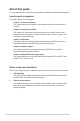
About this guide This user guide contains the information you need when installing and configuring the motherboard. How this guide is organized This guide contains the following parts: • • • • • Chapter 1: Product introduction This chapter describes the features of the motherboard and the new technology it supports. Chapter 2: Hardware information This chapter lists the hardware setup procedures that you have to perform when installing system components.
Conventions used in this guide To ensure that you perform certain tasks properly, take note of the following symbols used throughout this manual. DANGER/WARNING: Information to prevent injury to yourself when trying to complete a task. CAUTION: Information to prevent damage to the components when trying to complete a task. IMPORTANT: Instructions that you MUST follow to complete a task. NOTE: Tips and additional information to help you complete a task.
P7P55D Deluxe specifications summary CPU LGA1156 socket for Intel® Core™ i7/ Core™ i5 Processors/ Supports Intel® Turbo Boost Technology * Refer to www.asus.com for Intel CPU support list Chipset Intel® P55 Express Chipset Memory 4 x DIMM, max. 16GB, DDR3 2133(O.C.)* / 1600 / 1333 / 1066 MHz, non-ECC, un-buffered memory Dual channel memory architecture Supports Intel® Extreme Memory Profile (XMP) * Hyper DIMM support is subject to the physical characteristics of individual CPUs.
P7P55D Deluxe specifications summary ASUS Unique Features ASUS Hybrid Processor—TurboV EVO: - Auto Tuning, TurboV and Turbo Key) - ASUS TurboV Remote ASUS Hybrid Phase: - T.
P7P55D Deluxe specifications summary Internal I/O Connectors 3 x USB connectors support additional 6 USB ports 1 x IDE connector 7 x SATA connectors 2 x Drive Xpert SATA connectors (dark blue and gray) 1 x CPU Fan connector 2 x Chassis Fan connectors (1 x 4-pin, 1 x 3-pin) 1 x Power Fan connector 1 x IEEE1394a connector Front panel audio connector 1 x S/PDIF Out Header 1 x CD audio in 1 x 24-pin ATX Power connector 1 x 8-pin EATX 12V Power connectors System Panel (Q-Connector) 1 x TURBO_CON header (for Tur
Chapter 1 Chapter 1: 1.1 Product introduction Welcome! Thank you for buying an ASUS® P7P55D Deluxe motherboard! The motherboard delivers a host of new features and latest technologies, making it another standout in the long line of ASUS quality motherboards! Before you start installing the motherboard, and hardware devices on it, check the items in your package with the list below. 1.2 Package contents Check your motherboard package for the following items.
1.3 Special features 1.3.1 Product highlights Chapter 1 Green ASUS This motherboard and its packaging comply with the European Union’s Restriction on the use of Hazardous Substances (RoHS). This is in line with the ASUS vision of creating environment-friendly and recyclable products/packagings to safeguard consumers’ health while minimizing the impact on the environment.
1.3.2 ASUS Xtreme Design—Hybrid Processor TurboV EVO Chapter 1 Ultimate O.C. Processor The ultimate O.C. processor satisfies every level of overclockers—from die-hard enthusiasts to beginners. Auto tuning intelligently pushes the system to the fastest clock speeds while maintaining stability. Turbo Key boosts performance with just one touch; while TurboV offers more options to advanced overclockers to achieve world O.C. record. Refer to page 4-10 for details.
1.3.5 ASUS Exclusive Features ASUS Drive Xpert Chapter 1 Plug and Safe! Without BIOS setups, the ASUS exclusive Drive Xpert is ideal for anyone who needs to secure data on their hard drives or enhance hard drive performances without the hassles of complicated configurations. With Drive Xpert’s user-friendly graphical user interface, users can easily arrange hard drive backups or enhance their hard drive transfer rates—ensuring that data is looked after every moment, every day.
Fan Xpert Chapter 1 Active Quiet & Cool ASUS Fan Xpert intelligently allows users to adjust both the CPU and chassis fan speed according to different ambient temperature, which is caused by different climate conditions in different geographic regions and system loading. Built-in variety of useful profiles offer flexible controls of fan speed to achieve a quiet and cool environment. Refer to page 4-5 for details.
ASUS Q-Connector Chapter 1 Make connection quick and accurate! The ASUS Q-Connector allows you to connect or disconnect chassis front panel cables in one easy step with one complete module. This unique module eliminates the trouble of plugging in one cable at a time, making connection quick and accurate. Refer to page 2-41 for details. ASUS EZ-Flash 2 Simply update BIOS from a USB flash drive before entering the OS EZ Flash 2 is a user-friendly BIOS update utility.
Chapter 2 Chapter 2: 2.1 Before you proceed Hardware information Take note of the following precautions before you install motherboard components or change any motherboard settings. • Unplug the power cord from the wall socket before touching any component. • Before handling components, use a grounded wrist strap or touch a safely grounded object or a metal object, such as the power supply case, to avoid damaging them due to static electricity.
2.2 Motherboard overview 2.2.1 Motherboard layout Chapter 2 Refer to 2.7 Connectors for more information about rear panel connectors and internal connectors.
Layout contents Connectors/Jumpers/Slots Page 1. ATX power connectors (24-pin EATXPWR, 8-pin EATX12V) 2-39 2. LGA1156 CPU Socket 2-5 3. CPU / IMC / DRAM overvoltage setting switches (OV_DRAM; OV_IMC; OV_CPU) 2-26 4. DDR3 DIMM slots 2-10 5. CPU, chassis, and power fan connectors (4-pin CPU_FAN, 4-pin CHA_FAN1, 3-pin CHA_FAN2, 3-pin PWR_FAN) 2-37 6. Serial port connector (10-1 pin COM1) 2-36 7. MemOK! switch 2-25 8. IDE connector (40-1 pin PRI_EIDE) 2-31 9.
2.2.3 Placement direction When installing the motherboard, ensure that you place it into the chassis in the correct orientation. The edge with external ports goes to the rear part of the chassis as indicated in the image below. 2.2.4 Screw holes Place nine screws into the holes indicated by circles to secure the motherboard to the chassis. DO NOT overtighten the screws! Doing so can damage the motherboard.
2.3 Central Processing Unit (CPU) The motherboard comes with a surface mount LGA1156 socket designed for the Intel® Core™ i7 / Core™ i5 Processors. 2.3.1 • Upon purchase of the motherboard, ensure that the PnP cap is on the socket and the socket contacts are not bent. Contact your retailer immediately if the PnP cap is missing, or if you see any damage to the PnP cap/socket contacts/motherboard components. ASUS will shoulder the cost of repair only if the damage is shipment/ transit-related.
3. Lift the load lever in the direction of the arrow until the load plate is completely lifted. Load plate Chapter 2 4. 5. Remove the PnP cap from the CPU socket. PnP cap Position the CPU over the socket, ensuring that the gold triangle is on the bottom‑left corner of the socket, and then fit the socket alignment keys into the CPU notches. The CPU fits in only one correct orientation.
6. Apply some Thermal Interface Material to the exposed area of the CPU that the heatsink will be in contact with, ensuring that it is spread in an even thin layer. Some heatsinks come with preapplied thermal paste. If so, skip this step. 7. Close the load plate (A), and then push down the load lever (B), ensuring that the front edge of the load plate slides under the retention lock (C). Chapter 2 The Thermal Interface Material is toxic and inedible. DO NOT eat it.
2.3.2 Installing the CPU heatsink and fan The Intel® LGA1156 processor requires a specially designed heatsink and fan assembly to ensure optimum thermal condition and performance. • When you buy a boxed Intel® processor, the package includes the CPU fan and heatsink assembly. If you buy a CPU separately, ensure that you use only Intel®‑certified multi‑directional heatsink and fan. • Your Intel® LGA1156 heatsink and fan assembly comes in a push-pin design and requires no tool to install.
Connect the CPU fan cable to the connector on the motherboard labeled CPU_FAN. Chapter 2 3. DO NOT forget to connect the CPU fan connector! Hardware monitoring errors can occur if you fail to plug this connector. 2.3.3 Uninstalling the CPU heatsink and fan To uninstall the CPU heatsink and fan: 1. 2. 3. 4. Disconnect the CPU fan cable from the connector on the motherboard. Rotate each fastener counterclockwise.
2.4 System memory 2.4.1 Overview The motherboard comes with four Double Data Rate 3 (DDR3) Dual Inline Memory Modules (DIMM) sockets. A DDR3 module has the same physical dimensions as a DDR2 DIMM but is notched differently to prevent installation on a DDR2 DIMM socket. DDR3 modules are developed for better performance with less power consumption.
2.4.2 Memory configurations • You may install varying memory sizes in Channel A and Channel B. The system maps the total size of the lower-sized channel for the dual-channel configuration. Any excess memory from the higher-sized channel is then mapped for single-channel operation. • Due to Intel spec definition, X.M.P. DIMMs and DDR3-1600 are supported for one DIMM per channel only. • According to Intel CPU spec, DIMM voltage below 1.65V is recommended to protect the CPU.
P7P55D Deluxe Motherboard Qualified Vendors Lists (QVL) DDR3-1067MHz capability for CPU at 2.66, 2.8 and 2.93GHz Vendor Part No. Size SS/ DS Chip Brand Chip NO. Timing Dimm(Bios) CORSAIR CM3X1024-1066C7 1GB DS N/A Heat-Sink Package 7 Crucial CT25664BA1067.16SFD 2GB DS MICRON D9JNL 7 Crucial ELPIDA ELPIDA ELPIDA ELPIDA Hynix Hynix Hynix Hynix KINGSTON KINGSTON KINGSTON MICRON Chapter 2 MICRON MICRON MICRON SAMSUNG Transcend Asint Asint Elixir WINTEC CT12864BA1067.
P7P55D Deluxe Motherboard Qualified Vendors Lists (QVL) DDR3-1333MHz capability for CPU at 2.66, 2.8 and 2.93GHz (continued) Part No. Size SS/ DS Chip Brand Chip NO. Timing Dimm(Bios) ELPIDA EBJ21UE8BAW0-DJ-E 2GB DS ELPIDA J1108BABG-DJ-E 9(1333-9-9-9-24) G.SKILL F3-10600CL7D-2GBPI SS N/A Heat-Sink Package (1337-7-7-7-18) G.SKILL F3-10600CL8D-2GBHK SS N/A Heat-Sink Package F3-10666CL7T6GBPK(XMP) 2GB (Kit of 2) G.
P7P55D Deluxe Motherboard Qualified Vendors Lists (QVL) DDR3-1333MHz capability for CPU at 2.66, 2.8 and 2.93GHz (continued) DIMM socket support (Optional) Vendor Part No. Size SS/ DS Chip Brand Chip NO. Timing Dimm(Bios) Voltage B* C* PVT33G1333ELK 3GB (Kit of 3) A* Patriot SS N/A Heat-Sink Package 9-9-9-24(1066-7-7-7-20) 1.65 • • • Patriot PVS34G1333ELK DS N/A Heat-Sink Package 9-9-9-24(1066-7-7-7-20) 1.
P7P55D Deluxe Motherboard Qualified Vendors Lists (QVL) DDR3-1600MHz capability for CPU at 2.66GHz (continued) Chip NO. Timing Lable(Bios) Voltage 4GB(Kit of 2) DS N/A Heat-Sink Package 7-7-7-20(1066-7-7-7-20) 1.9 6GB(Kit of 3) DS N/A Heat-Sink Package 9-9-9-24(1066-7-7-7-20) 1.65 Vendor Part No.
P7P55D Deluxe Motherboard Qualified Vendors Lists (QVL) DDR3-1625MHz capability for CPU at 2.66GHz SS/ DS Chip Brand Chip NO. KINGSTON KHX13000D3LLK2/2GN(EPP) 2GB(Kit of 2) SS N/A Heat-Sink Package 1.9 KINGSTON KHX13000D3LLK2/2GXN SS N/A Heat-Sink Package 1.9 Vendor Part No. Size KINGSTON KHX13000D3LLK2/2GX(XMP) 2GB(Kit of 2) 2GB(Kit of 2) SS N/A Timing Dimm(Bios) Voltage Heat-Sink Package 1.
P7P55D Deluxe Motherboard Qualified Vendors Lists (QVL) DDR3-1866MHz capability for CPU at 2.66GHz Vendor Part No. Size SS/ Chip Chip NO.
P7P55D Deluxe Motherboard Qualified Vendors Lists (QVL) DDR3-2000MHz capability for CPU at 2.8 and 2.93GHz DIMM socket support Voltage (Optional) Vendor Part No. Size SS/ DS Chip Brand Chip NO. Timing Dimm(Bios) Apacer 78.0AGCQ.CBZ(XMP) 3GB(Kit of 3) SS N/A Heat-Sink Package 9-9-9-27(1066-8-8-8-20) G.SKILL F3-16000CL7T-6GBPS(XMP) 6GB(Kit of 3) DS N/A Heat-Sink Package 7-8-7-20(1066-8-8-8-20) 1.65 Crucial G.SKILL BL12864BE2009.
2.4.3 Installing a DIMM Ensure to unplug the power supply before adding or removing DIMMs or other system components. Failure to do so may cause severe damage to both the motherboard and the components. 2 To install a DIMM 2. Unlock a DIMM socket by pressing the retaining clip outward. Align a DIMM on the socket such that the notch on the DIMM matches the break on the socket. 1 Chapter 2 1. DIMM notch Unlocked retaining clip A DIMM is keyed with a notch so that it fits in only one direction.
2.5 Expansion slots In the future, you may need to install expansion cards. The following subsections describe the slots and the expansion cards that they support. Ensure to unplug the power cord before adding or removing expansion cards. Failure to do so may cause you physical injury and damage motherboard components. 2.5.1 Installing an expansion card To install an expansion card 1. 2. Chapter 2 3. 4. 5. 6.
2.5.
2.5.4 PCI slots The PCI slots support cards such as a LAN card, SCSI card, USB card, and other cards that comply with PCI specifications. Refer to the figure below for the location of the slot. 2.5.5 PCI Express 2.0 x1 slots (2.5GT/s) This motherboard supports PCI Express x1 network cards, SCSI cards and other cards that comply with the PCI Express specifications. Refer to the figure below for the location of the slot. 2.5.6 PCI Express 2.0 x16 slots This motherboard has three PCI Express 2.
PCI Express operating mode PCIe x16_1 PCIe x16_2 PCIe x16_3 Single VGA/PCIe card x16 (Recommend for single VGA) N/A x4 (PCIe card) Dual VGA/PCIe card x8 x8 x4 Triple VGA/PCIe card x8 x8 x4 • In single VGA card mode, use first the PCIe 2.0 x16_1 slot (blue) for a PCI Express x16 graphics card to get better performance. • In CrossFireX™ or SLI™ mode, use the PCIe 2.0 x16_1 (blue) and PCIe 2.0 x16_2 (dark blue) slots for PCI Express x16 graphics cards to get better performance.
2.6 Onboard switches Onboard switches allow you to fine-tune performance when working on a bare or opencase system. This is ideal for overclockers and gamers who continually change settings to enhance system performance. 1. Power-on switch The motherboard comes with a power-on switch that allows you to power up or wake up the system.
MemOK! switch Installing DIMMs that are incompaible with the motherboard may cause system boot failure, and the DRAM_LED near the MemOK! switch lights continuously. Press and hold the MemOK! switch until the DRAM_LED starts blinking to begin automatic memory compatibility tuning for successful boot. • Refer to section 2.8 Onboard LEDs for the exact location of the DRAM_LED. • The DRAM_LED also lights when the DIMM is not properly installed.
4. CPU / IMC / DRAM overvoltage setting switches (OV_DRAM, OV_IMC, OV_CPU) These switches allow you to enable or disable the advanced CPU, Integrated Memory Controller (IMC), and DRAM overvoltage settings in BIOS. Read the following information before you change the switch settings. Chapter 2 The LED color indicates the voltage setting status of CPU, IMC and DRAM. 2-26 OV_CPU OV_IMC OV_DRAM Default 0.85V to 1.7V up to 1.7V up to 2.0V Enable OV (red) 1.25V to 2.1V up to 1.9V up to 2.
Connectors 2.7.1 Rear panel connectors Chapter 2 2.7 Rear panel connectors 1. PS/2 mouse port (green) 8. USB 2.0 ports 7 and 8 2. Coaxial S/PDIF Out port 9. Optical S/PDIF Out port 3. LAN (RJ-45) port 2* 10. USB 2.0 ports 5 and 6 4. IEEE 1394a port 11. USB 2.0 ports 3 and 4 5. LAN (RJ-45) port 1* 12. USB 2.0 ports 1 and 2 6. PS/2 keyboard port (purple) 13. Audio I/O ports** 7. Clear CMOS switch *and **: Refer to the tables on the next page for LAN port and audio port definitions.
*LAN port LED indications ACT/LINK LED Activity Link LED Speed LED Status Description Status Description OFF No link OFF 10 Mbps connection ORANGE Linked ORANGE 100 Mbps connection BLINKING Data activity GREEN 1 Gbps connection SPEED LED LAN port ** Audio 2, 4, 6, 8, or 10-channel configuration Chapter 2 Port Headset 2-channel 4-channel 6-channel 8-channel 10-channel Light Blue Line In Line In Line In Line In Additional Side Speaker Out Lime Line Out Pink Mic In Front
Connect to Stereo / 2.1-channel Speakers Chapter 2 Connect to 4.1-channel Speakers Connect to 5.
Connect to 7.1-channel Speakers Chapter 2 Connect to 9.
2.7.3 IDE connector (40-1 pin PRI_IDE) The onboard IDE connector is for the Ultra DMA 133/100/66 signal cable. There are three connectors on each Ultra DMA 133/100/66 signal cable: blue, black, and gray. Connect the blue connector to the motherboard’s IDE connector, then select one of the following modes to configure your device.
2. Intel® P55 Serial ATA connectors (7-pin SATA 1-6) These connectors are for the Serial ATA signal cables for Serial ATA hard disk drives and optical disc drives. If you installed Serial ATA hard disk drives, you can create a RAID 0, 1, 5, and 10 configuration with the Intel® Matrix Storage Technology through the onboard Intel® P55 chipset. Chapter 2 2-32 • These connectors are set to Standard IDE mode by default.
3. JMicron® JMB322 Serial ATA connectors (7-pin SATA_E1 [gray], SATA_E2 [dark blue]) Chapter 2 These connectors are for the Serial ATA signal cables for Serial ATA hard disk drives. If you installed two Serial ATA hard disk drives, you can create a EZ Backup or a Super Speed configuration with the Drive Xpert Technology through the onboard JMicron® JMB322 controller.
4. Chapter 2 5. 2-34 JMicron® JMB363 Serial ATA connector (7-pin SATA_E3 [black]) This connector is for the Serial ATA signal cables for Serial ATA hard disk drives and optical disc drives. TurboV Remote connector (5-pin TURBO_CON) This connector is for the bundled TurboV Remote. TurboV Remote allows you to turn on/off the computer, adjust EPU modes and system bus speed, and launch Turbo Key profiles for system overclocking without interrupting on-going work or games.
USB connectors (10-1 pin USB910; USB1112; USB1314) These connectors are for USB 2.0 ports. Connect the USB module cable to any of these connectors, then install the module to a slot opening at the back of the system chassis. These USB connectors comply with USB 2.0 specification that supports up to 480 Mbps connection speed. Chapter 2 6. Never connect a 1394 cable to the USB connectors.
8. IEEE 1394a port connector (10-1 pin IE1394_2) This connector is for an IEEE 1394a port. Connect the IEEE 1394a module cable to this connector, then install the module to a slot opening at the back of the system chassis. Chapter 2 Never connect a USB cable to the IEEE 1394a connector. Doing so will damage the motherboard! The IEEE 1394a module is purchased separately. 9. Serial port connector (10-1 pin COM1) This connector is for a serial (COM) port.
10. CPU, chassis, and power fan connectors (4-pin CPU_FAN; 4-pin CHA_FAN1; 3-pin CHA_FAN2; 3-pin PWR_FAN) Chapter 2 The fan connectors support cooling fans of 350 mA~1000 mA (12 W max.) or a total of 1 A~4 A (48 W max.) at +12V. Connect the fan cables to the fan connectors on the motherboard, ensuring that the black wire of each cable matches the ground pin of the connector. Do not forget to connect the fan cables to the fan connectors.
11. Digital audio connector (4-1 pin SPDIF_OUT) This connector is for an additional Sony/Philips Digital Interface (S/PDIF) port(s). Connect the S/PDIF Out module cable to this connector, then install the module to a slot opening at the back of the system chassis. Chapter 2 The S/PDIF module is purchased separately. 12. Front panel audio connector (10-1 pin AAFP) This connector is for a chassis-mounted front panel audio I/O module that supports either HD Audio or legacy AC`97 audio standard.
ATX power connectors (24-pin EATXPWR; 8-pin EATX12V) These connectors are for ATX power supply plugs. The power supply plugs are designed to fit these connectors in only one orientation. Find the proper orientation and push down firmly until the connectors completely fit. • For a fully configured system, we recommend that you use a power supply unit (PSU) that complies with ATX 12 V Specification 2.0 (or later version) and provides a minimum power of 350 W.
14. System panel connector (20-8 pin PANEL) This connector supports several chassis-mounted functions. Chapter 2 • • • • • 2-40 System power LED (2-pin PLED) This 2-pin connector is for the system power LED. Connect the chassis power LED cable to this connector. The system power LED lights up when you turn on the system power, and blinks when the system is in sleep mode. Hard disk drive activity LED (2-pin IDE_LED) This 2-pin connector is for the HDD Activity LED.
2.7.4. ASUS Q-Connector (system panel) Use the ASUS Q-Connector to connect/disconnect the chassis front panel cables. Connect the front panel cables to the ASUS Q-Connector. Refer to the labels on the Q-Connector to know the detailed pin definitions, and then match them to their respective front panel cable labels. The labels on the front panel cables may vary depending on the chassis model. IDE_LED+ IDE_LED- PWR Ground Reset Ground 2.
2.8 1. Onboard LEDs POST State LEDs POST State LEDs check key components (CPU, DRAM, VGA card, and HDD) in sequence during motherboard booting process. If an error is found , the LED next to the error device will continue lighting until the problem is solved. This user-friendly design provides an intuitional way to locate the root problem within a second. Chapter 2 You may disable the POST State LEDs in BIOS. Refer to section 3.8.2 Boot Setting Configuration for details. 2.
2.9 Starting up for the first time 1. After making all the connections, replace the system case cover. 3. Connect the power cord to the power connector at the back of the system chassis. 2. 4. 5. Be sure that all switches are off. Connect the power cord to a power outlet that is equipped with a surge protector. Turn on the devices in the following order: a. Monitor c. System power b. 6.
Chapter 2 2-44 Chapter 2: Hardware information
Chapter 3 Chapter 3: 3.1 Knowing BIOS BIOS setup BIOS (Basic Input and Output System) stores system hardware settings such as storage device configuration, overclocking settings, advanced power management, and boot device configuration that are needed for system startup in the motherboard CMOS. In normal circumstances, the default BIOS settings apply to most conditions to ensure optimum performance.
3.2.1 ASUS Update utility The ASUS Update is a utility that allows you to manage, save, and update the motherboard BIOS in Windows® environment. The ASUS Update utility allows you to: • Save the current BIOS file • Update the BIOS from an updated BIOS file • • • Download the latest BIOS file from the Internet Update the BIOS directly from the Internet View the BIOS version information This utility is available in the support DVD that comes with the motherboard package.
3. Select the ASUS FTP site nearest you to avoid network traffic, or click Auto Select. Click Next. 4. From the FTP site, select the BIOS version that you wish to download. Click Next. 5. Follow the onscreen instructions to complete the update process. The ASUS Update utility is capable of updating itself through the Internet. Always update the utility to avail all its features. Updating the BIOS through a BIOS file To update the BIOS through a BIOS file: 2.
3.2.2 ASUS EZ Flash 2 utility The ASUS EZ Flash 2 feature allows you to update the BIOS without having to use a DOS‑based utility. The EZ Flash 2 utility is built in the BIOS chip so it is accessible by pressing + during the Power-On Self Tests (POST). Before you start using this utility, download the latest BIOS from the ASUS website at www. asus.com. To update the BIOS using EZ Flash 2 1.
3.2.3 ASUS CrashFree BIOS 3 utility The ASUS CrashFree BIOS 3 utility is an auto recovery tool that allows you to restore the BIOS file when it fails or gets corrupted during the updating process. You can restore a corrupted BIOS file using the motherboard support DVD or a USB flash drive that contains the BIOS file. The BIOS file in the motherboard support DVD may be older than the BIOS file published on the ASUS official website. If you want to use the newer BIOS file, download the file at support.asus.
3.3 BIOS setup program A BIOS Setup program is provided for BIOS item modification. When you start up the computer, the system provides you with the opportunity to run this program. Press during the Power-On Self-Test (POST) to enter the Setup utility. Otherwise, POST continues with its test routines. If you wish to enter Setup after POST, restart the system by pressing + + , or by pressing the reset button on the system chassis.
3.3.3 Navigation keys At the bottom right corner of a menu screen are the navigation keys for that particular menu. Use the navigation keys to select items in the menu and change the settings. The navigation keys may differ from one screen to another. 3.3.4 Menu items The highlighted item on the menu bar displays the specific items for that menu. For example, selecting Main shows the Main menu items. The other items (Advanced, Power, Boot, and Exit) on the menu bar have their respective menu items. 3.
3.4 Main menu When you enter the BIOS Setup program, the Main menu screen appears, giving you an overview of the basic system information. You can also set the system time and date and BIOS language in this menu. Refer to 3.3.1 BIOS menu screen for information on the menu screen items and how to navigate through them.
Type [Auto] Allows you to select the type of SATA drive installed. [Not Installed] [Auto] [CDROM] [ARMD] Select this option if no SATA drive is installed. Allows automatic selection of the appropriate SATA device type. Select this option if you are specifically configuring a CD-ROM drive. Select [ARMD] (ATAPI Removable Media Device) if your device is either a ZIP, LS-120, or MO drive. LBA/Large Mode [Auto] Enables or disables the LBA (Logical Block Addressing) mode.
3.4.2 Storage Configuration The Storage Configuration menu allows you to configure your storage devices. Select an item then press to display the submenu. BIOS SETUP UTILITY Main Storage Configuration SATA Configuraton Configure SATA as [Enhanced] [IDE] Hard Disk Write Protect IDE Detect Time Out (Sec) [Disabled] [35] Set [Compatible Mode] when Legacy OS (i.e. WIN ME, 98, NT4.0, MS DOS) is used. Set [Enhanced Mode] when Native OS (i.e. WIN2000, Win XP, Vista is used.
SATA Port1–6 [XXXX] Displays the status of auto-detection of SATA devices. BIOS SETUP UTILITY Main Select the type of devices connected to the system. SATA Port1 Device :Not Detected SATA Port1 SMART Monitoring [Auto] [Enabled] SATA Port1 [Auto] Allows you to select the type of device connected to the system. Configuration options: [Auto] [Not Installed] SMART Monitoring [Enabled] Allows you to set the Self-Monitoring, Analysis and Reporting Technology.
3.5 Ai Tweaker menu The Ai Tweaker menu items allow you to configure overclocking-related items. Be cautious when changing the settings of the Ai Tweaker menu items. Incorrect field values can cause the system to malfunction. The configuration options for this chapter vary depending on the CPU and DIMM model you installed on the motherboard.
3.5.3 Ai Overclock Tuner [Auto] Allows selection of CPU overclocking options to achieve desired CPU internal frequency. Select either one of the preset overclocking configuration options: Manual Allows you to individually set overclocking parameters. Auto Loads the optimal settings for the system. D.O.C.P Overclocks DRAM frequency by adjusting BCLK frequency. X.M.P. If you install memory module(s) supporting the eXtreme Memory Profile (X.M.P.
3.5.5 Intel(R) SpeedStep(TM) Tech [Enabled] When set to [Disabled], the CPU runs at its default speed. When set to [Enabled], the CPU speed is controlled by the operating system. Configuration options: [Disabled] [Enabled] 3.5.6 Intel(R) TurboMode Tech [Enabled] This item appears only if you set the CPU Ratio Setting item to [Auto]. Turbo mode allows processor cores to run faster than marked frequency in specific condition. Configuration options: [Disabled] [Enabled] 3.5.
1st Information: 6-6-6-15-4-36-6-5-16 The values vary depending on your settings of the following sub-items: DRAM CAS# Latency [Auto] Configuration options: [Auto] [3 DRAM Clock] [4 DRAM Clock] – [10 DRAM Clock] [11 DRAM Clock] DRAM RAS# to CAS# Delay [Auto] Configuration options: [Auto] [3 DRAM Clock] [4 DRAM Clock] – [9 DRAM Clock] [10 DRAM Clock] DRAM RAS# PRE Time [Auto] Configuration options: [Auto] [3 DRAM Clock] [4 DRAM Clock] – [9 DRAM Clock] [10 DRAM Clock] DRAM RAS# ACT Time [Auto] Configuration
DRAM WRITE to READ Delay(DR) [Auto] Configuration options: [Auto] [1 DRAM Clock] – [8 DRAM Clock] DRAM WRITE to READ Delay(SR) [Auto] Configuration options: [Auto] [10 DRAM Clock] – [22 DRAM Clock] DRAM READ to WRITE Delay(DD) [Auto] Configuration options: [Auto] [2 DRAM Clock] – [14 DRAM Clock] DRAM READ to WRITE Delay(DR) [Auto] Configuration options: [Auto] [2 DRAM Clock] – [14 DRAM Clock] DRAM READ to WRITE Delay(SR) [Auto] Configuration options: [Auto] [2 DRAM Clock] – [14 DRAM Clock] DRAM READ to READ
Offset Voltage [Auto] This item appears only when you set the CPU Voltage Mode item to [Offset] and allows you to set the Offset voltage. The values range from 0.00625V to 0.50000V with a 0.00625V interval. Offset Sign [-] This item appears only when you set the Offset Voltage item to a value other than [Auto]. [+] To offset the voltage by a positive value. [–] To offset the voltage by a negative value.
3.5.16 PCH Voltage [Auto] Allows you to set the Platform Controller Hub voltage. The values range from 1.05V to 1.15V with a 0.10V interval. • The values of the IMC Voltage, DRAM Voltage, and CPU PLL Voltage items are labeled in different color, indicating the risk levels of high voltage settings. Refer to the table on the next page for details. • The system may need better cooling system to work stably under high voltage settings. Blue Yellow Purple Red IMC Voltage 1.10000V– 1.16875V 1.
3.6 Advanced menu The Advanced menu items allow you to change the settings for the CPU and other system devices. Be cautious when changing the settings of the Advanced menu items. Incorrect field values can cause the system to malfunction. Main Ai Tweaker BIOS SETUP UTILITY Advanced Power Boot CPU Configuration North Bridge Configuration Onboard Devices Configuration USB Configuration PCIPnP Intel VT-d Tools Exit Configure CPU.
CPU Ratio Setting [Auto] Allows you to adjust the ratio between CPU Core Clock and BCLK Frequency. Use the <+> and <-> keys to adjust the value. The valid value ranges differently according to your CPU model. C1E Support [Enabled] [Enabled] [Disabled] Enables the C1E support function. This item should be enabled in order to enable the Enhanced Halt Sate. Disables this function. Hardware Prefetcher [Enabled] [Enabled] [Disabled] Enables the Hardware Prefetcher function.
Active Processor Cores [All] [All] [1] [2] Activate all CPU cores in the processor package. Activate only 1 CPU core in the processor package. Activate 2 CPU cores in the processor package. A20M [Disabled] [Enabled] [Disabled] Legacy OSes and APs may need this function enabled. Disables this function. Intel(R) SpeedStep (TM) Tech [Enabled] [Enabled] [Disabled] The CPU speed is controlled by the operating system. The CPU runs at its default speed.
3.6.3 Onboard Devices Configuration Advanced BIOS SETUP UTILITY Onboard Devices Configuration HDA Controller Front Panel Type Realtek LAN1 LAN Boot ROM Realtek LAN2 LAN Boot ROM Onboard 1394 Controller J-Micron SATA/PATA Controller Serial Port1 Address [Enabled] [HD Audio] [Enabled] [Disabled] [Enabled] [Disabled] [Enabled] [IDE Mode] [3F8/IRQ4] Options Enabled Disabled HDA Controller [Enabled] [Enabled] Enables the High Definition Audio Controller. [Disabled] Disables the controller.
3.6.4 USB Configuration The items in this menu allows you to change the USB-related features. Select an item then press to display the configuration options. Advanced BIOS SETUP UTILITY USB Configuration Options Module Version - 2.24.5-13.4 USB Devices Enabled: 2 Hubs USB Functions Legacy USB Support BIOS EHCI Hand-Off Disabled Enabled [Enabled] [Auto] [Enabled] The USB Devices Enabled item shows the auto-detected values. If no USB device is detected, the item shows None.
3.6.5 PCIPnP The PCIPnP menu items allow you to change the advanced settings for PCI/PnP devices. Advanced BIOS SETUP UTILITY Advanced PCI/PnP Settings WARNING: Setting wrong values in below sections may cause system to malfunction. Plug And Play O/S NO: lets the BIOS configure all the devices in the system. [No] Plug And Play O/S [No] [Yes] [No] 3.6.
3.7 Power menu The Power menu items allow you to change the settings for the Advanced Power Management (APM). Select an item then press to display the configuration options. Main Ai Tweaker BIOS SETUP UTILITY Advanced Power Boot Suspend Mode Repost Video on S3 Resume ACPI 2.0 Support ACPI APIC Support EuP Ready [Auto] [No] [Disabled] [Enabled] [Disabled] Tools Exit Select the ACPI state used for System Suspend.
3.7.6 APM Configuration BIOS SETUP UTILITY Power APM Configuration Restore on AC Power Loss [Power Off] Power On By RTC Alarm [Disabled] Power On By External Modems [Disalbed] Power On By PCI Devices [Disabled] Power On By PCIE Devices [Disabled] Power On By���������������������������� PS/2 Keyboard [Disabled] Power On By������������������������� PS/2 Mouse [Disabled] to select whether or not to restart the system after AC power loss.
Power On By PS/2 Mouse [Disabled] [Disabled] [Enabled] 3.7.7 Disables the Power On by a PS/2 mouse. Enables the Power On by a PS/2 mouse. This feature requires an ATX power supply that provides at least 1A on the +5VSB lead.
Chassis Q-Fan Control [Disabled] [Disabled] [Enabled] Disables the Chassis Q-Fan control feature. Enables the Chassis Q-Fan control feature. Chassis Fan Profile [Standard] This item appears only when you enable the Chassis Q-Fan Control feature and allows you to set the appropriate performance level of the chassis fan. [Standard] Sets to [Standard] to make the chassis fan automatically adjust depending on the chassis temperature.
3.8 Boot menu The Boot menu items allow you to change the system boot options. Select an item then press to display the submenu. Main Ai Tweaker BIOS SETUP UTILITY Advanced Power Boot Tools Exit Specifies the Boot Device Priority sequence. Boot Settings Boot Device Priority Boot Settings Configuration Security A virtual floppy disk drive (Floppy Drive B: ) may appear when you set the CD-ROM drive as the first boot device.
3.8.2 Boot Settings Configuration BIOS SETUP UTILITY Boot Boot Settings Configuration Quick Boot Full Screen Logo AddOn ROM Display Mode Bootup Num-Lock Wait For ‘F1’ If Error Hit ‘DEL’ Message Display POST State LEDs [Enabled] [Enabled] [Force BIOS] [On] [Enabled] [Enabled] [Enabled] Allows BIOS to skip certain tests while booting. This will decrease the time needed to boot the system. Quick Boot [Enabled] [Disabled] When set to [Disabled], BIOS performs all the POST items.
3.8.3 Security The Security menu items allow you to change the system security settings. Select an item then press to display the configuration options. BIOS SETUP UTILITY Boot Security Settings Supervisor Password User Password : Not Installed : Not Installed to change password. again to disable password. Change Supervisor Password Change User Passward Change Supervisor Password Select this item to set or change the supervisor password.
BIOS SETUP UTILITY Boot Security Settings Supervisor Password User Password : Installed : Installed Change Supervisor Password User Access Level Change User Password Clear User Password Password Check to change password. again to disabled password. [Full Access] [Setup] User Access Level [Full Access] This item allows you to select the access restriction to the Setup items. [No Access] Prevents user access to the Setup utility.
3.9 Tools menu The Tools menu items allow you to configure options for special functions. Select an item then press to display the submenu. Main BIOS SETUP UTILITY Advanced Power Boot Ai Tweaker Tools Exit ASUS O.C. Profile Drive Xpert Configuration AI NET 2 ASUS EZ Flash 2 Express Gate Enter OS Timer Reset User Data ID LED [Auto] [10 Seconds] [No] [Enabled] ←→ ↑↓ Enter F1 F10 ESC Select Screen Select Item Go to Sub Screen General Help Save and Exit Exit v02.
ASUSTek O.C. Profile Utility V2.00b Current CMOS BOARD: P7P55D Deluxe VER: 0166 DATE: 07/08/2009 Restore CMOS BOARD: Unknown VER: Unknown DATE: Unknown PATH: A:\ A: Note [Enter] Select or Load [Up/Down/Home/End] Move 3.9.2 [Tab] Switch [B] Backup [V] Drive Info [Esc] Exit • This function can support devices such as a USB flash disk with FAT 32/16 format and single partition only.
Changed Mode This item appears only when you select a Drive Xpert mode to update and displays the Drive Xpert mode that you have changed. Ultra Space This item appears only when you have created a drive partition using the Ultra Space function. Drive Xpert Mode Update: Update To Super Speed [Press Enter] Allows you to use the Super Speed function that combines two hard drives as one single drive partition. All original data of the two hard drives will be erased for Super Speed setup.
3.9.3 AI NET 2 BIOS SETUP UTILITY AI NET 2 Pair Status Check Realtek LAN cable during POST. Length Check Realtek LAN cable Tools [Disabled] It will take 3 to 10 seconds to diagnose LAN cable. Check Realtek LAN Cable [Disabled] [Disabled] [Enabled] 3.9.4 BIOS will not check the Realtek LAN cable during the Power-On Self-Test (POST). BIOS checks the Realtek LAN cable during the Power-On Self-Test (POST). ASUS EZ Flash 2 Allows you to run ASUS EZ Flash 2.
3.10 Exit menu The Exit menu items allow you to load the optimal or failsafe default values for the BIOS items, and save or discard your changes to the BIOS items. Main Ai Tweaker Exit Options Exit & Save Changes Exit & Discard Changes Discard Changes Load Setup Defaults BIOS SETUP UTILITY Advanced Power Boot Tools Exit Exit system setup after saving the changes. F10 key can be used for this operation.
Chapter 3 3-38 Chapter 3: BIOS setup
Chapter 4 Chapter 4: 4.1 Software support Installing an operating system This motherboard supports Windows® XP/ 64-bit XP/ Vista / 64-bit Vista / 7 / 64-bit 7 operating systems (OS). Always install the latest OS version and corresponding updates to maximize the features of your hardware. 4.2 • Motherboard settings and hardware options vary. Use the setup procedures presented in this chapter for reference only. Refer to your OS documentation for detailed information.
4.2.2 Obtaining the software manuals The software manuals are included in the support DVD. Follow the instructions below to get the necessary software manuals. The software manual files are in Portable Document Format (PDF). Install the Adobe® Acrobat® Reader from the Utilities menu before opening the files. 1. Click the Manual tab. Click ASUS Motherboard Utility Guide from the manual list on the left. 2. The Manual folder of the support DVD appears. Double-click the folder of your selected software.
4.3 Software information Most of the applications in the support DVD have wizards that will conveniently guide you through the installation. View the online help or readme file that came with the software application for more information. 4.3.1 ASUS PC Probe II PC Probe II is a utility that monitors the computer’s vital components, and detects and alerts you of any problem with these components. PC Probe II senses fan rotations, CPU temperature, and system voltages, among others.
4.3.2 ASUS AI Suite ASUS AI Suite allows you to launch several ASUS utilities easily. Launching AI Suite 1. Install AI Suite from the motherboard support DVD. 2. Launch AI Suite by clicking Start > All Programs > ASUS > AI Suite > AI Suite v1.xx. xx. The AI Suite main window appears. 3. The AI Suite icon appears in the Windows® notification area. If you minimize the application main window, click this icon to restore the window.
4.3.3 ASUS Fan Xpert Asus Fan Xpert allows you to adjust both the CPU and chassis fan speeds according to different ambient temperatures and your PC’s system loading. The various fan profiles offer flexible controls of fan speeds to achieve a quiet and cool system environment. Launching Fan Xpert After installing AI Suite from the motherboard support DVD, launch Fan Xpert by doubleclicking the AI Suite tray icon and then clicking the Fan Xpert button on the AI Suite main window.
4.3.4 ASUS EPU-6 Engine ASUS EPU-6 Engine is an energy-efficient tool that satisfies different computing needs. This utility provides four modes that you can select to enhance system performance or save power: • Turbo Mode • Medium Power Saving Mode • High Performance Mode • Max. Power Saving Mode Selecting Auto Mode will have the system shift modes automatically according to current system status.
4.3.5 ASUS Express Gate ASUS Express Gate is an instant-on environment that gives you quick access to the Internet, Skype, and viewing your pictures. Within a few seconds of powering on your computer, you will be at the Express Gate menu where you can start the web browser, Skype, or other Express Gate applications. Notices about ASUS Express Gate • Ensure to install ASUS Express Gate from the motherboard support DVD before use. • ASUS Express Gate supports SATA devices in IDE mode only.
4.3.6 VIA® High ����������������������������� Definition Audio utility The VIA® High Definition Audio CODEC provides 10-channel audio capability to deliver the ultimate audio experience on your computer. The software provides Jack-Detection,MultiStreaming, Front Panel Jack-Retasking and S/PDIF Out support. Follow the installation wizard to install the VIA® Audio Driver from the support CD/DVD that came with the motherboard package.
4.3.7 ASUS Drive Xpert Drive Xpert, an ASUS exclusive technology, secures the data on your hard disk and enhances hard drive performance without the hassles of complicated configurations. With its user-friendly graphical user interface, you can easily arrange hard drive backups or enhance the hard drive’s transfer rate. Drive Xpert modes There are three main modes for Drive Xpert: EZ Backup, Super Speed and Normal Mode. • • • EZ Backup allows one hard disk to backup the other hard disk automatically.
4.4 ASUS Unique Overclocking Utility— TurboV EVO ASUS TurboV EVO introduces TurboV and Turbo Key—two powerful tools that allow you to overclock your system effectively. Install ASUS TurboV EVO from the support DVD that came with the motherboard package. If the TurboV EVO is correctly installed, you will find the TurboV EVO icon on the Windows notification area. Click on the icon to display the TurboV EVO control panel. Refer to the software manual in the support DVD or visit the ASUS website at www.asus.
4.4.2 Using ASUS TurboV Auto Tuning Mode 1. Click the Auto Tuning tab and then click Start. You can also click More Setting first to configure more overclocking parameters before starting autooverclocking. 2. Read through the warning messages and click Yes to start auto-overclocking. 3. An animation appears indicating the overclocking process. Click Stop if you want to cancel the current Overclocking process. • After pressing Start, the system starts performance tuning and may reboot 2 to 3 times.
4.4.3 Using ASUS Turbo Key ASUS Turbo Key allows the user to set a group of hot-keys into physical overclocking buttons. After the easy setup, Turbo Key can boost performances without interrupting ongoing work or games—with just one touch! If the TurboV EVO is correctly installed, you will find the TurboV EVO icon on the Windows notification area. Click on the icon to display the TurboV EVO control panel. Click the Turbo Key tab to switch to the Turbo Key interface. Configuring ASUS Turbo Key 1 2 3 4 1.
4.5 RAID configurations The motherboard comes with the Intel® P55 chipset that allows you to configure Serial ATA hard disk drives as RAID sets. The motherboard supports the following RAID configurations: RAID 0, RAID 1, RAID 10 and RAID 5. 4.5.1 • You must install Windows® XP Service Pack 2 or later versions before using Serial ATA hard disk drives. The Serial ATA RAID feature is available only if you are using Windows® XP SP2 or later versions.
4.5.2 Installing Serial ATA hard disks The motherboard supports Serial ATA hard disk drives. For optimal performance, install identical drives of the same model and capacity when creating a disk array. To install the SATA hard disks for a RAID configuration: 1. Install the SATA hard disks into the drive bays. 3. Connect a SATA power cable to the power connector on each drive. 2. Connect the SATA signal cables. 4.5.
The navigation keys at the bottom of the screen allow you to move through the menus and select the menu options. The RAID BIOS setup screens shown in this section are for reference only and may not exactly match the items on your screen. The utility supports maximum four hard disk drives for RAID configuration. Creating a RAID volume To create a RAID set 1. From the utility main menu, select 1. Create RAID Volume and press . The following screen appears.
5. 6. Use the up/down arrow key to select a drive, and then press to select. A small triangle marks the selected drive. Press after completing your selection. Use the up/down arrow key to select the stripe size for the RAID array (for RAID 0, 10 and 5 only), and then press . The available stripe size values range from 4 KB to 128 KB.
Deleting a RAID set Take caution when deleting a RAID set. You will lose all data on the hard disk drives when you delete a RAID set. To delete a RAID set 1. From the utility main menu, select 2. Delete RAID Volume and press . The following screen appears. Intel(R) Matrix Storage Manager option ROM v8.9.0.1014 PCH-D wRAID5 Copyright(C) 2003-09 Intel Corporation. All Rights Reserved. [ DELETE VOLUME MENU ] Name Volume0 Level RAID0(Stripe) Drives 2 Capacity 298.
4.6 Creating a RAID driver disk A floppy disk with the RAID driver is required when installing Windows® XP operating system on a hard disk drive that is included in a RAID set. For Windows® Vista or later operating systems, use either a floppy disk or a USB flash drive with the RAID driver. 4.6.1 • The motherboard does not provide a floppy drive connector. You have to use a USB floppy disk drive when creating a SATA RAID driver disk.
4.6.3 Installing the RAID driver during Windows® OS installation To install the RAID driver for Windows® XP 1. 2. 3. 4. During the OS installation, the system prompts you to press the F6 key to install thirdparty SCSI or RAID driver. Press , and then insert the floppy disk with RAID driver into the USB floppy disk drive. When prompted to select the SCSI adapter to install, ensure that you select Intel(R) ICH8R/ICH9R/ICH10R/DO/PCH SATA RAID Controller.
4. Click Details tab. The Vendor ID (VID) and Product ID (PID) are displayed. 5. Browse the contents of the RAID driver disk to locate the file txtsetup.oem. 6. 7. Double-click the file. A window appears, allowing you to select the program for opening the oem file. Use Notepad to open the file.
8. 9. Find the [HardwareIds.scsi.iaAHCI_PCH] and [HardwareIds.scsi.iastor_8R9R10RDOPCH] sections in the txtsetup.oem file. Type the following line to the bottom of the two sections: id = “USB\VID_xxxx&PID_xxxx”, “usbstor” [HardwareIds.scsi.iaAHCI_PCH] id= “PCI\VEN_8086&DEV_3A22&CC_0106”,”iaStor” id= “USB\VID_03EE&PID_6901”, “usbstor” [HardwareIds.scsi.iaStor_8R9R10RDOPCH] id= “PCI\VEN_8086&DEV_3A22&CC_0106”,”iaStor” id= “USB\VID_03EE&PID_6901”, “usbstor” Add the same line to both sections.
Chapter 4 4-22 Chapter 4: Software support
Chapter 5 Chapter 5: Multiple GPU technology support 5.1 ATI® CrossFireX™ technology The motherboard supports the ATI® CrossFireX™ technology that allows you to install multigraphics processing units (GPU) graphics cards. Follow the installation procedures in this section. 5.1.1 • • • • Requirements In CrossFireX mode, you should have two identical CrossFireX-ready graphics cards or one CrossFireX-ready dual-GPU graphics card that are ATI® certified.
5.1.3 Installing two CrossFireX™ graphics cards The following pictures are for reference only. The graphics cards and the motherboard layout may vary with models, but the installation steps remain the same. Chapter 5 1. 2. 3. 4. Prepare two CrossFireX-ready graphics cards. Insert the two graphics card into the PCIEX16 slots. If your motherboard has more than two PCIEX16 slots, refer to Chapter 2 in this user manual for the locations of the PCIEX16 slots recommended for multi-graphics card installation.
5.1.4 2. 3. Prepare three CrossFireX-ready graphics cards. Insert the three graphics card into the PCIEX16 slots. If your motherboard has more than three PCIEX16 slots, refer to Chapter 2 in this user manual for the locations of the PCIEX16 slots recommended for multi-graphics card installation. Ensure that the cards are properly seated on the slots. 4. Align and firmly insert the two CrossFireX bridge connectors to the goldfingers on each graphics card. Ensure that the connectors are firmly in place.
5.1.5 Installing the device drivers Refer to the documentation that came with your graphics card package to install the device drivers. Chapter 5 5.1.6 • Ensure that your PCI Express graphics card driver supports the ATI® CrossFireX™ technology. Download the latest driver from the AMD website (www.amd.com). • If you are using a Triple CrossFireX system, ensure to install the ATI Catalyst® driver under Windows® Vista™ OS.
Enabling CrossFireX settings 2. 3. 4. In the Catalyst Control Center window, click Graphics Settings > CrossFireX > Configure. From the Graphics Adapter list, select the graphics card to act as the display GPU. Select Enable CrossFireX. Click Apply, and then click OK to exit the window. Chapter 5 1. 2 3 1 4 Enabling Triple CrossFireX settings 1. 2. 3. 4. 5. In the Catalyst Control Center window, click Graphics Settings > CrossFireX > Configure.
5.2 NVIDIA® SLI™ technology The motherboard supports the NVIDIA® SLI™ (Scalable Link Interface) technology that allows you to install multi-graphics processing units (GPU) graphics cards. Follow the installation procedures in this section. Chapter 5 5.2.1 • • • Requirements In SLI mode, you should have two identical SLI-ready graphics cards that are NVIDIA® certified. Ensure that your graphics card driver supports the NVIDIA SLI technology. Download the latest driver from the NVIDIA website (www.
5. 6. Align and firmly insert the SLI bridge connector to the goldfingers on each graphics card. Ensure that the connector is firmly in place. Connect two independent auxiliary power sources from the power supply to the two graphics cards separately. Chapter 5 4. Connect a VGA or a DVI cable to the graphics card. SLI bridge Goldfingers 5.2.3 Installing the device drivers Refer to the documentation that came with your graphics card package to install the device drivers.
If you cannot see the NVIDIA Control Panel item in step (A), select Personalize. B2. From the Personalization window, select Display Settings. B3. From the Display Settings dialog box, click Advanced Settings. Chapter 5 B1.
Select the NVIDIA GeForce tab, and then click Start the NVIDIA Control Panel. B5. The NVIDIA Control Panel window appears. Chapter 5 B4. Enabling SLI settings From the NVIDIA Control Panel window, select Set SLI Configuration. Click Enable SLI and set the display for viewing SLI rendered content. When done, click Apply.
Chapter 5 5-10 Chapter 5: Multiple GPU technology support