Motherboard P8B75-M LX
E7992 Third Edition (V3) January 2013 Copyright © 2013 ASUSTeK COMPUTER INC. All Rights Reserved. No part of this manual, including the products and software described in it, may be reproduced, transmitted, transcribed, stored in a retrieval system, or translated into any language in any form or by any means, except documentation kept by the purchaser for backup purposes, without the express written permission of ASUSTeK COMPUTER INC. (“ASUS”).
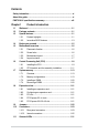
Contents Safety information....................................................................................... vi About this guide.......................................................................................... vi P8B75-M LX specifications summary...................................................... viii Chapter 1 Product introduction 1.1 Welcome!....................................................................................... 1-1 1.2 Package contents..............................
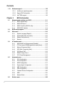
Contents 1.13 Software support......................................................................... 1-32 1.13.1 Installing an operating system....................................... 1-32 1.13.2 Support DVD information............................................... 1-32 1.13.3 Intel® SBA support.......................................................... 1-33 Chapter 2 2.1 Managing and updating your BIOS............................................. 2-1 2.1.1 ASUS Update utility....................
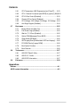
Contents 2.6.1 CPU Temperature / MB Temperature [xxxºC/xxxºF]....... 2-23 2.6.2 CPU / Chassis Fan Speed [xxxx RPM] or [Ignore] / [N/A]2-23 2.7 2.8 2.9 2.6.3 CPU Q-Fan Control [Enabled]....................................... 2-23 2.6.4 Chassis Q-Fan Control [Enabled].................................. 2-24 2.6.5 CPU Voltage, 3.3V Voltage, 5V Voltage, 12V Voltage... 2-24 2.6.6 Anti Surge Support [Enabled]........................................ 2-24 Boot menu.....................................
Safety information Electrical safety • To prevent electric shock hazard, disconnect the power cable from the electric outlet before relocating the system. • When adding or removing devices to or from the system, ensure that the power cables for the devices are unplugged before the signal cables are connected. If possible, disconnect all power cables from the existing system before you add a device.
Conventions used in this guide To ensure that you perform certain tasks properly, take note of the following symbols used throughout this manual. DANGER/WARNING: Information to prevent injury to yourself when trying to complete a task. CAUTION: Information to prevent damage to the components when trying to complete a task. IMPORTANT: Instructions that you MUST follow to complete a task. NOTE: Tips and additional information to help you complete a task.
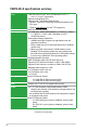
P8B75-M LX specifications summary CPU Chipset Memory Graphics Expansion slots Storage LAN Audio USB LGA1155 socket for Intel® 2nd / 3rd Generation Core™ i7 / Core™ i5 / Core™ i3 processors Supports Intel 22/32nm CPU Supports Intel® Turbo Boost Technology 2.0 * The Intel® Turbo Boost Technology 2.0 support depends on the CPU types. ** Refer to www.asus.com for Intel® CPU support list. Intel® B75 Express Chipset 2 x DIMM, max. 16GB*, DDR3 2200(O.C.) / 2133(O.C.) / 2000(O. C.) /1800(O.C.
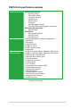
P8B75-M LX specifications summary ASUS unique features ASUS Exclusive Features: - ASUS GPU Boost - ASUS USB 3.
P8B75-M LX specifications summary BIOS features Manageability Accessories Support DVD Form factor 128 Mb Flash ROM, AMI BIOS, PnP, DMI2.0, WfM2.0, SM BIOS 2.5, ACPI 2.0a, Multi-language BIOS, ASUS EZ Flash 2, ASUS CrashFree BIOS 3 WfM 2.0, DMI 2.0, WOL by PME, WOR by PME, PXE 1 x Serial ATA 3.0Gb/s cable 1 x Serial ATA 6.0Gb/s cable 1 x I/O shield 1 x User Manual 1 x Support DVD Drivers ASUS utilities ASUS Update Anti-virus software (OEM version) MicroATX form factor: 9.6”x 7.8” (24.4cm x 19.
Chapter 1 Product introduction 1.1 Welcome! Thank you for buying an ASUS® P8B75-M LX motherboard! The motherboard delivers a host of new features and latest technologies, making it another standout in the long line of ASUS quality motherboards! Before you start installing the motherboard, and hardware devices on it, check the items in your package with the list below. 1.2 Package contents Check your motherboard package for the following items.
Intel® B75 Express Chipset The Intel® B75 Express Chipset is the latest single-chipset designed to support the 1155 socket Intel® 3rd/2nd generation Core™ i7 / Core™ i5 / Core™ i3 processors. It provides improved performance by utilizing serial point-to-point links, allowing increased bandwidth and stability. In addition, B75 chipset provides 4 USB 3.0 ports that retrieves data 10 times faster.
1.3.2 Innovative ASUS features ASUS UEFI BIOS Flexible and Easy BIOS Interface ASUS UEFI BIOS offers the first mouse-controlled graphical BIOS designed with selectable modes, providing a user-friendly interface that goes beyond the traditional keyboard-only controls. It also natively supports fully-utilized hard drives larger than 2.2TB in 64-bit operating systems. ASUS exclusive interface EZ Mode displays frequently-accessed info.
USB 3.0 Boost With USB 3.0 Boost technology, a USB device’s transmission speed is significantly increased, adding to an already impressive fast USB 3.0 transfer speed. ASUS software automatically accelerates data speeds for compatible USB 3.0 peripherals without the need for any user interaction. GPU Boost Go to the Limit with iGPU Level Up! GPU Boost accelerates the integrated GPU for extreme graphics performance. The user-friendly interface facilitates flexible frequency adjustments.
ASUS MyLogo2™ This feature allows you to convert your favorite photo into a 256-color boot logo for a more colorful and vivid image on your screen. ASUS CrashFree BIOS 3 ASUS CrashFree BIOS 3 is an auto-recovery tool that allows you to restore a corrupted BIOS file using the bundled support DVD or USB flash disk that contains the latest BIOS file. ASUS EZ Flash 2 ASUS EZ Flash 2 is a utility that allows you to update the BIOS without using an OS-based utility. C.P.R. (CPU Parameter Recall) The BIOS C.P.
1.5 Motherboard overview Before you install the motherboard, study the configuration of your chassis to ensure that the motherboard fits into it. Ensure that you unplug the power cord before installing or removing the motherboard. Failure to do so can cause you physical injury and damage motherboard components. 1.5.1 Placement direction 1.5.2 Screw holes When installing the motherboard, ensure that you place it into the chassis in the correct orientation.
1.5.3 Motherboard layout 1 2 3 1 4 19.8cm(7.8in) KBMS_USB34 DVI CPU_FAN USB3_34 LAN_USB12 Lithium Cell CMOS Power RTL 8111F 24.4cm(9.
1.6 Central Processing Unit (CPU) The motherboard comes with a surface mount LGA1155 socket designed for the Intel® 3rd/2nd generation Core™ i7 / Core™ i5 / Core™ i3 processors. P8B75-M LX P8B75-M LX CPU socket LGA1155 Unplug all power cables before installing the CPU. • Upon purchase of the motherboard, ensure that the PnP cap is on the socket and the socket contacts are not bent.
1.6.1 Installing the CPU The LGA1156 CPU is incompatible with the LGA1155 socket. DO NOT install a LGA1156 CPU on the LGA1155 socket.
4 C A B 5 1-10 Chapter 1: Product introduction
1.6.2 CPU heatsink and fan assembly installation Apply the Thermal Interface Material to the CPU heatsink and CPU before you install the heatsink and fan if necessary.
To uninstall the CPU heatsink and fan assembly 1 2 A B B A 1-12 Chapter 1: Product introduction
1.7 System memory 1.7.1 Overview DIMM_A1 DIMM_B1 The motherboard comes with four Double Data Rate 3 (DDR3) Dual Inline Memory Modules (DIMM) sockets. A DDR3 module has the same physical dimensions as a DDR2 DIMM but is notched differently to prevent installation on a DDR2 DIMM socket. DDR3 modules are developed for better performance with less power consumption.
P8B75-M LX Motherboard Qualified Vendors Lists (QVL) DDR3-2400 MHz capability Vendors CORSAIR G.SKILL G.SKILL GEIL KINGMAX Transcend Transcend Transcend Part No. CMGTX8(XMP) F3-19200CL11Q16GBZHD(XMP1.3) F3-19200CL9D4GBPIS(XMP) GET34GB2400C9DC(XMP) FLLE88F-C8KKAA HAIS(XMP) TX2400KLU4GK(427652)(XMP) TX2400KLU-4GK (381850)(XMP) TX2400KLU4GK(374243)(XMP) Size 8GB(2GBx 4) SS/ DS Chip Brand Chip NO. Timing Voltage DIMM socket support (Optional) 2 DIMMs • 1 DIMM SS - - 10-12-10-27 1.
DDR3-2000 MHz capability Vendors Apacer CORSAIR CORSAIR G.SKILL G.SKILL G.SKILL GEIL KINGSTON KINGSTON KINGSTON KINGSTON KINGSTON Transcend DS SS DS DS DS DS DS - - DIMM socket Voltage support (Optional) 1 DIMM 2 DIMMs 9-9-9-27 1.65V • • 10-10-10-27 1.50V • • 8-9-8-24 1.65V • • 9-9-9-24 1.65V • • 9-9-9-27 1.65V • • 6-9-6-24 1.65V • • 9-9-9-28 1.65V • • 4GB ( 2x 2GB ) DS - - - 1.65V • • 4GB ( 2x 2GB ) DS - - - 1.65V • • 4GB(2 x 2GB) DS - - 9 1.65V • • 6GB ( 3x 2GB ) DS - - - 1.
DDR3-1600 MHz capability Vendors Part No. SS/ DS Chip Brand Chip NO. Timing Voltage DIMM socket support (Optional) 1 DIMM 2 DIMMs - - • • 8-8-8-24 1.65V-1.85V • • - - • • - 3CCD-1509 A EL1126T 3CCD-1509 A EL1126T - 9-9-9-24 7-9-7-21 8-8-8-24 8-8-8-24 8-8-8-24 9-9-9-24 7-8-7-20 9-9-9-24 8-8-8-24 8-8-8-24 9-9-9-24 9-9-9-24 7-8-7-20 9-9-9-24 9-9-9-24 7-7-7-24 7-8-7-24 8-8-8-24 9-9-9-24 9-9-9-24 9-9-9-24 7-8-7-24 8-8-8-24 9-9-9-24 1.55V-1.75V 1.55V-1.75V 1.65V 1.65V 1.65V 1.65V 1.65V 1.
DDR3-1333 MHz capability Vendors A-DATA A-DATA A-DATA A-DATA A-DATA A-DATA Part No. Size SS/ DS Chip Brand Chip NO.
DDR3-1066 MHz capability KINGSTON KVR1333D3N9/2G KVR1333D3N9/2GSP(low profile) KINGSTON KVR1333D3N9 /2G-SP(low profile) KINGSTON KHX1333C7D3 K2/4GX(XMP) KINGSTON KHX1333C9D3 UK2/4GX(XMP) KINGSTON KVR1333D3N 9/4G(low profile) KINGSTON KVR1333D3N 9/4G(low profile) KINGSTON KVR1333D3N9/4G KINGSTON KVR1333D3N9/4G KINGSTON KVR1333D3N9/ 4G-SP(low profile) Micron MT4JTF12864AZ-1G4D1 Micron MT8JTF12864AZ-1G4F1 Micron MT8JTF25664AZ-1G4D1 Micron MT8JTF25664AZ-1G4M1 MT16JTF25664AZMicron 1G4F1 MT16JTF51264AZMicron 1G4
DDR3-1066 MHz capability Vendors Part No. Crucial Crucial ELPIDA ELPIDA CT12864BA1067.8FF CT25664BA1067.16FF EBJ10UE8EDF0-AE-F EBJ21UE8EDF0-AE-F KINGSTON KVR1066D3N7/1G(low profile) KINGSTON KVR1066D3N7/2G KINGSTON KVR1066D3N7/4G Micron MT8JTF12864AZ-1G1F1 Micron MT16JTF25664AZ-1G1F1 Kingtiger 2GB DIMM PC3-8500 Size SS/ DS 1GB 2GB 1GB 2GB SS DS SS DS Micron Micron ELPIDA ELPIDA 9GF22D9KPT 9HF22D9KPT J1108EDSE-DJ-F J1108EDSE-DJ-F 7 7 - 1.35V(low voltage) 1.
1.7.3 Installing a DIMM Unplug the power supply before adding or removing DIMMs or other system components. Failure to do so can cause severe damage to both the motherboard and the components. 1. Press the retaining clips outward to unlock a DIMM socket. 2. Align a DIMM on the socket such that the notch on the DIMM matches the DIMM slot key on the socket. 2 DIMM notch 1 DIMM slot key Unlocked retaining clip A DIMM is keyed with a notch so that it fits in only one direction.
1.8 Expansion slots In the future, you may need to install expansion cards. The following sub‑sections describe the slots and the expansion cards that they support. Unplug the power cord before adding or removing expansion cards. Failure to do so may cause you physical injury and damage motherboard components. 1.8.1 Installing an expansion card To install an expansion card: 1.
IRQ assignments for this motherboard Intel PCH SATA controller #0 Intel PCH SATA controller #1 Realtek 8111F controller 1.9 1. A B C D E F G H – – – shared – – – – – – – shared – – – – shared – – – – – – – Jumpers Clear RTC RAM (3-pin CLRTC) This jumper allows you to clear the Real Time Clock (RTC) RAM in CMOS. You can clear the CMOS memory of date, time, and system setup parameters by erasing the CMOS RTC RAM data.
1.10 Connectors 1.10.1 Rear panel connectors 1 2 10 9 8 7 6 3 4 5 1. PS/2 Mouse port (green). This port is for a PS/2 mouse. 2. LAN (RJ-45) port. This port allows Gigabit connection to a Local Area Network (LAN) through a network hub. Refer to the table below for the LAN port LED indications.
6. USB 2.0 ports 1 and 2. These two 4-pin Universal Serial Bus (USB) ports are available for connecting USB 2.0/1.1 devices. 7. USB 3.0 ports 1 and 2. These two 9-pin Universal Serial Bus (USB) ports connect to USB 3.0/2.0 devices. • DO NOT connect a keyboard / mouse to any USB 3.0 port when installing Windows® operating system. • Due to USB 3.0 controller limitation, USB 3.0 devices can only be used under Windows® OS environment and after the USB 3.0 driver installation. • USB 3.
1.10.2 1. Internal connectors Front panel audio connector (10-1 pin AAFP) NC AGND NC NC SENSE2_RETUR AGND NC SENSE1_RETUR This connector is for a chassis-mounted front panel audio I/O module that supports either HD Audio or legacy AC`97 audio standard. Connect one end of the front panel audio I/O module cable to this connector.
3. ATX power connectors (24-pin EATXPWR, 4-pin ATX12V) These connectors are for ATX power supply plugs. The power supply plugs are designed to fit these connectors in only one orientation. Find the proper orientation and push down firmly until the connectors completely fit.
5. CPU and chassis fan connectors (4-pin CPU_FAN, 3-pin CHA_FAN) Connect the fan cables to the fan connectors on the motherboard, ensuring that the black wire of each cable matches the ground pin of the connector. CPU FAN PWM CPU FAN IN +12V GND CPU_FAN CHA_FAN P8B75-M LX GND CHA FAN PWR CHA FAN IN P8B75-M LX fan connectors Do not forget to connect the fan cables to the fan connectors. Insufficient air flow inside the system may damage the motherboard components.
7. System panel connector (10-1 pin F_PANEL) This connector supports several chassis-mounted functions. F_PANEL PLED+ PLEDPWR GND PWR LED PWR BTN HD_LED+ HD_LEDGround Reset PIN 1 P8B75-M LX +HD_LED RESET P8B75-M LX System panel connector • System power LED (2-pin PLED) • This 2-pin connector is for the system power LED. Connect the chassis power LED cable to this connector. The system power LED lights up when you turn on the system power, and blinks when the system is in sleep mode.
9. Intel® B75 Serial ATA 3.0Gb/s connectors (7-pin SATA3G_1~5 [blue]) These connectors connect to Serial ATA 3.0 Gb/s hard disk drives and optical drives via Serial ATA 3.0 Gb/s signal cables.
11. USB 3.0 connector (20-1 pin USB3_34) This connector is for the additional USB 3.0 ports. Connect the USB 3.0 bracket cable to this connector, then install the USB 3.0 bracket to the rear side of the chassis. If your chassis support customized front panel installation, with ASUS USB 3.0 header, you can have a front panel USB 3.0 solution. USB3_34 P8B75-M LX P8B75-M LX USB3.0 Front panel connector The USB 3.0 module is purchased separately. 12. USB 2.
13. Chassis intrusion connector (4-1 pin CHASSIS) This connector is for a chassis-mounted intrusion detection sensor or switch. Connect one end of the chassis intrusion sensor or switch cable to this connector. The chassis intrusion sensor or switch sends a high-level signal to this connector when a chassis component is removed or replaced. The signal is then generated as a chassis intrusion event. By default, the pin labeled “Chassis Signal” and “Ground” are shorted with a jumper cap.
1.13 Software support 1.13.1 Installing an operating system This motherboard supports Windows® XP / Vista / 7 Operating Systems (OS). Always install the latest OS version and corresponding updates to maximize the features of your hardware. • Motherboard settings and hardware options vary. Refer to your OS documentation for detailed information.
1.13.3 Intel® SBA support Intel SBA (Small Business Advantage) is a combination of hardware and software that provides unique security and productivity capabilities designed for small businesses. ® Intel® SBA requires MEI driver (AMT host software kit) installed. Platform requirements: • Windows® 7 (32/64bit) • Panther Point PCH with Core™ Ivy Bridge CPU or Sandy Bridge CPU (Chief River/ Maho Bay platforms) with 5MB vPro ME 8.
1-34 Chapter 1: Product introduction
Chapter 2 BIOS information 2.1 Managing and updating your BIOS Save a copy of the original motherboard BIOS file to a USB flash disk in case you need to restore the BIOS in the future. Copy the original motherboard BIOS using the ASUS Update utility. 2.1.1 ASUS Update utility The ASUS Update is a utility that allows you to manage, save, and update the motherboard BIOS in Windows® environment. • ASUS Update requires an Internet connection either through a network or an Internet Service Provider (ISP).
The ASUS Update utility is capable of updating itself through the Internet. Always update the utility to avail all its features. Updating from a BIOS file 3. a. Select Update BIOS from file, then click Next. b. Locate the BIOS file from the Open window, then click Open. Follow the onscreen instructions to complete the updating process. 2.1.2 ASUS EZ Flash 2 The ASUS EZ Flash 2 feature allows you to update the BIOS without using an OS‑based utility.
3. Press to switch to the Drive field. 4. Press the Up/Down arrow keys to find the USB flash disk that contains the latest BIOS, and then press . 5. Press to switch to the Folder Info field. 6. Press the Up/Down arrow keys to find the BIOS file, and then press to perform the BIOS update process. Reboot the system when the update process is done. • This function supports USB flash disks with FAT 32/16 format and single partition only.
2.1.4 ASUS BIOS Updater The ASUS BIOS Updater allows you to update BIOS in DOS environment. This utility also allows you to copy the current BIOS file that you can use as a backup when the BIOS fails or gets corrupted during the updating process. The succeeding utility screens are for reference only. The actual utility screen displays may not be same as shown. Before updating BIOS 1. Prepare the motherboard support DVD and a USB flash drive in FAT32/16 format and single partition. 2.
Updating the BIOS file To update the BIOS file using BIOS Updater 1. At the FreeDOS prompt, type bupdater /pc /g and press . D:\>bupdater /pc /g 2. The BIOS Updater screen appears as below. ASUSTek BIOS Updater for DOS V1.28 Current ROM BOARD: P8B75-M LX VER: 0203 DATE: 04/01/2012 Update ROM BOARD: Unknown VER: Unknown DATE: Unknown PATH: A:\ P8B75LX.CAP A: Note [Enter] Select or Load [Up/Down/Home/End] Move 3.
2.2 BIOS setup program Use the BIOS Setup program to update the BIOS or configure its parameters. The BIOS screens include navigation keys and brief online help to guide you in using the BIOS Setup program. Entering BIOS Setup at startup To enter BIOS Setup at startup: • Press during the Power-On Self Test (POST). If you do not press , POST continues with its routines. Entering BIOS Setup after POST To enter BIOS Setup after POST: • Press ++ simultaneously.
EZ Mode By default, the EZ Mode screen appears when you enter the BIOS setup program. The EZ Mode provides you an overview of the basic system information, and allows you to select the display language, system performance mode and boot device priority. To access the Advanced Mode, click Exit/Advanced Mode, then select Advanced Mode or press F7 hot key for the advanced BIOS settings. The default screen for entering the BIOS setup program can be changed. Refer to the Setup Mode item in section 2.
Advanced Mode The Advanced Mode provides advanced options for experienced end-users to configure the BIOS settings. The figure below shows an example of the Advanced Mode. Refer to the following sections for the detailed configurations. To access the EZ Mode, click Exit, then select ASUS EZ Mode.
Pop-up window Select a menu item and press to display a pop-up window with the configuration options for that item. Scroll bar A scroll bar appears on the right side of a menu screen when there are items that do not fit on the screen. Press the Up/Down arrow keys or / keys to display the other items on the screen. Navigation keys At the bottom right corner of the menu screen are the navigation keys for the BIOS setup program.
2.3 Main menu The Main menu screen appears when you enter the Advanced Mode of the BIOS Setup program. The Main menu provides you an overview of the basic system information, and allows you to set the system date, time, language, and security settings. UEFI BIOS Utility - Advanced Mode Main Ai Tweaker Exit Advanced Monitor BIOS Information BIOS Version Build Date ME Version South Bridge Stepping 0203 x64 04/01/2012 8.0.0.1441 C1 CPU Information Genuine Intel(R) CPU @ 2.
Administrator Password If you have set an administrator password, we recommend that you enter the administrator password for accessing the system. Otherwise, you might be able to see or change only selected fields in the BIOS setup program. To set an administrator password: 1. Select the Administrator Password item and press . 2. From the Create New Password box, key in a password, then press . 3. Confirm the password when prompted. To change an administrator password: 1.
2.4 Ai Tweaker menu The Ai Tweaker menu items allow you to configure overclocking-related items. Be cautious when changing the settings of the Ai Tweaker menu items. Incorrect field values can cause the system to malfunction. The configuration options for this section vary depending on the CPU and DIMM model you installed on the motherboard. Target DRAM Speed : xxxxMHz Displays the current DRAM speed. 2.4.1 [Enabled] [Disabled] 2.4.2 ASUS MultiCore Enhancement [Enabled].
2.4.3 Memory Frequency [Auto] Allows you to set the memory operating frequency. The configuration options vary with the CPU bus speed : DRAM speed ratio mode item settings. Selecting a very high memory frequency may cause the system to become unstable! If this happens, revert to the default setting. 2.4.4 iGPU Max. Frequency [Auto] 2.4.5 GPU Boost [OK] 2.4.6 DRAM Timing Control Allows you to set the iGPU maximum frequency. The values range from xxxxMHz (by CPU) to 3000MHz with a 50MHz interval.
Long Duration Power Limit [Auto] Allows you to limit the turbo ratio’s long duration power. Use the <+> and <-> keys to adjust the value. Long Duration Maintained [Auto] Allows you to maintain the turbo ratio’s long duration power. Use the <+> and <-> keys to adjust the value. Short Duration Power Limit [Auto] Allows you to limit the turbo ratio’s long duration power. Use the <+> and <-> keys to adjust the value.
2.5 Advanced menu The Advanced menu items allow you to change the settings for the CPU and other system devices. Be cautious when changing the settings of the Advanced menu items. Incorrect field values can cause the system to malfunction.
Execute Disable Bit [Enabled] [Enabled] [Disabled] Enables the No-Execution Page Protection Technology. Forces the XD feature flag to always return to zero (0). Intel® Virtualization Technology [Disabled] [Enabled] Allows a hardware platform to run multiple operating systems separately and simultaneously, enabling one system to virtually function as several systems. Disables this function.
Intel® Rapid Start Technology [Disabled] Allows you to enable or disable the Intel(R) Rapid Start Technology. Configuration options: [Enabled] [Disabled] The following three items appear only when you set the Intel(R) Rapid Start Technology to [Enabled]. Entry on S3 RTC Wake [Enabled] Allows you to enable or disable the iFFS invocation upon S3 RTC wake.
2.5.4 System Agent Configuration Memory Remap Feature [Enabled] [Enabled] [Disabled] Allow you to enable remapping the memory above 4GB. Disables this function. Graphics Configuration Primary Display [Auto] Allows you to decide which graphics controller to use as the primary boot device. Configuration options: [Auto] [iGPU] [PCIE] [PCI] iGPU Memory [64M] Allows you to select the amount of system memory allocated to DVMT 5.0 used by the iGPU.
WatchDog [Disabled] When set to [Enabled], the WatchDog Timer will monitor the time taken for each task performed by a software or hardware. Configuration options: [Enabled] [Disabled] The following two items become configurable only when you set the WatchDog Timer item to [Enabled]. OS Timer [0] Use the <+> and <-> keys to adjust the value or key in a number directly. BIOS Timer [0] Use the <+> and <-> keys to adjust the value or key in a number directly. 2.5.
2.5.7 Onboard Devices Configuration HD Audio Controller [Enabled] [Enabled] [Disabled] Enables the High Definition Audio Controller. Disables the controller. The following item appears only when you set the HD Audio Controller item to [Enabled]. Front Panel Type [HD] Allows you to set the front panel audio connector (AAFP) mode to legacy AC’97 or highdefinition audio depending on the audio standard that the front panel audio module supports.
2.5.8 APM Restore AC Power Loss [Power Off] [Power On] [Power Off] [Last State] The system goes into on state after an AC power loss. The system goes into off state after an AC power loss. The system goes into either off or on state, whatever the system state was before the AC power loss. Power On By PS/2 Keyboard [Disabled] [Disabled] [Space Bar] [Ctrl-Esc] [Power Key] Disables the Power On by a PS/2 keyboard. Sets the Space Bar on the PS/2 keyboard to turn on the system.
2.6 Monitor menu The Monitor menu displays the system temperature/power status, and allows you to change the fan settings.
2.6.1 CPU Temperature / MB Temperature [xxxºC/xxxºF] The onboard hardware monitor automatically detects and displays the CPU and motherboard temperatures. Select Ignore if you do not wish to display the detected temperatures. 2.6.2 CPU / Chassis Fan Speed [xxxx RPM] or [Ignore] / [N/A] The onboard hardware monitor automatically detects and displays the CPU and chassis fan speeds in rotations per minute (RPM). If the fan is not connected to the motherboard, the field shows N/A.
2.6.4 [Disabled] [Enabled] Chassis Q-Fan Control [Enabled] Disables the Chassis Q-Fan control feature. Enables the Chassis Q-Fan control feature. Chassis Fan Speed Low Limit [600 RPM] This item appears only when you enable the Chassis Q-Fan Control feature and allows you to disable or set the chassis fan warning speed.
2.7 Boot menu The Boot menu items allow you to change the system boot options. UEFI BIOS Utility - Advanced Mode Ai Tweaker Main Exit Advanced Bootup NumLock State Full Screen Logo Wait For ‘F1’ If Error Option ROM Messages Monitor On Boot Tool Select the keyboard NumLock state Enabled Enabled Force BIOS Setup Mode EZ Mode UEFI/Legacy Boot Enabled both...
2.7.4 [Force BIOS] Option ROM Messages [Force BIOS] [Keep Current] The third-party ROM messages will be forced to display during the boot sequence. The third-party ROM messages will be displayed only if the third-party manufacturer had set the add-on device to do so. 2.7.5 Setup Mode [EZ Mode] 2.7.6 UEFI/Legacy Boot [Enabled both UEFI and Legacy] 2.7.7 PCI ROM Priority [Legacy ROM] 2.7.
2.8 Tools menu The Tools menu items allow you to configure options for special functions. Select an item then press to display the submenu. UEFI BIOS Utility - Advanced Mode Ai Tweaker Main Advanced Exit Monitor Boot Tool Be used to update BIOS > ASUS EZ Flash 2 Utility > ASUS O.C. Profile > ASUS SPD Information 2.8.1 ASUS EZ Flash 2 Utility Allows you to run ASUS EZ Flash 2. Press [Enter] to launch the ASUS EZ Flash 2 screen. For more details, see section 2.1.2 ASUS EZ Flash 2. 2.8.
2.9 Exit menu The Exit menu items allow you to load the optimal default values for the BIOS items, and save or discard your changes to the BIOS items. You can access the EZ Mode from the Exit menu. Exit Load Optimized Defaults Save Changes & Reset Discard Changes & Exit ASUS EZ Mode Launch EFI Shell from filesystem device Load Optimized Defaults This option allows you to load the default values for each of the parameters on the Setup menus.
Appendices Notices Federal Communications Commission Statement This device complies with Part 15 of the FCC Rules. Operation is subject to the following two conditions: • This device may not cause harmful interference. • This device must accept any interference received including interference that may cause undesired operation. This equipment has been tested and found to comply with the limits for a Class B digital device, pursuant to Part 15 of the FCC Rules.
Canadian Department of Communications Statement This digital apparatus does not exceed the Class B limits for radio noise emissions from digital apparatus set out in the Radio Interference Regulations of the Canadian Department of Communications. This class B digital apparatus complies with Canadian ICES-003.
ASUS contact information ASUSTeK COMPUTER INC. Address Telephone Fax E-mail Web site Technical Support Telephone Online support 15 Li-Te Road, Peitou, Taipei, Taiwan 11259 +886-2-2894-3447 +886-2-2890-7798 info@asus.com.tw www.asus.com.tw +86-21-38429911 support.asus.
A-4 Appendices (510)739-3777/(510)608-4555 800 Corporate Way, Fremont, CA 94539. Asus Computer International Date : Signature : Representative Person’s Name : Apr. 25, 2012 Steve Chang / President This device complies with part 15 of the FCC Rules. Operation is subject to the following two conditions: (1) This device may not cause harmful interference, and (2) this device must accept any interference received, including interference that may cause undesired operation.