P8H61-M LE/USB3 Motherboard P8H61-M LE
E6476 First Edition (V1) February 2011 Copyright © 2011 ASUSTeK Computer Inc. All Rights Reserved. No part of this manual, including the products and software described in it, may be reproduced, transmitted, transcribed, stored in a retrieval system, or translated into any language in any form or by any means, except documentation kept by the purchaser for backup purposes, without the express written permission of ASUSTeK Computer Inc. (“ASUS”).
Contents Notices.......................................................................................................... vi Safety information...................................................................................... vii About this guide........................................................................................ viii P8H61-M LE Series specifications summary............................................ ix Chapter 1: Product introduction 1.1 Welcome!...............................
Contents 1.11 Software support......................................................................... 1-28 1.11.1 1.11.2 Chapter 2: 2.1 2.3 ASUS Update utility......................................................... 2-1 2.1.3 ASUS CrashFree BIOS 3 utility....................................... 2-3 2.1.4 ASUS BIOS Updater........................................................ 2-4 Main menu................................................................................... 2-11 2.3.
Contents 2.5.5 USB Configuration......................................................... 2-20 2.5.7 APM............................................................................... 2-22 2.5.6 2.6 Monitor menu.............................................................................. 2-23 2.6.1 CPU Temperature / MB Temperature............................. 2-23 2.6.3 CPU Q-Fan Control........................................................ 2-23 2.6.2 2.6.4 2.7 2.6.5 CPU Voltage, 3.
Notices Federal Communications Commission Statement This device complies with Part 15 of the FCC Rules. Operation is subject to the following two conditions: • This device may not cause harmful interference, and • This device must accept any interference received including interference that may cause undesired operation. This equipment has been tested and found to comply with the limits for a Class B digital device, pursuant to Part 15 of the FCC Rules.
REACH Complying with the REACH (Registration, Evaluation, Authorisation, and Restriction of Chemicals) regulatory framework, we published the chemical substances in our products at ASUS REACH website at http://csr.asus.com/english/REACH.htm. DO NOT throw the motherboard in municipal waste. This product has been designed to enable proper reuse of parts and recycling.
About this guide This user guide contains the information you need when installing and configuring the motherboard. How this guide is organized This guide contains the following parts: • Chapter 1: Product introduction • This chapter describes the features of the motherboard and the new technology it supports. Chapter 2: BIOS information This chapter tells how to change system settings through the BIOS Setup menus. Detailed descriptions of the BIOS parameters are also provided.
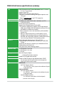
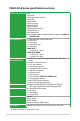
P8H61-M LE Series specifications summary CPU Chipset Memory Graphics Expansion slots Storage LAN Audio USB LGA1155 socket for Intel® Second Generation Core™ i7 / Core™ i5 / Core™ i3 processors Supports 32nm CPU Supports Intel® Turbo Boost technology 2.0 * The Intel® Turbo Boost technology 2.0 support depends on the CPU types. ** Refer to www.asus.com for Intel® CPU support list. Intel® H61 Express Chipset 2 x DIMM, max.
P8H61-M LE Series specifications summary ASUS unique features ESD GPU Boost ASUS Anti-Surge Protection ASUS EPU ASUS TurboV ASUS Fan Xpert ASUS EFI BIOS ASUS AI Suite II ASUS CrashFree BIOS 3 ASUS EZ Flash 2 ASUS MyLogo 2™ 100% All High-quality Conductive Polymer Capacitors (P8H61-M LE/USB3 only) Rear panel ports 1 x PS/2 keyboard / mouse combo port 1 x DVI-D port 1 x D-Sub port 1 x LAN (RJ-45) port 3 x Audio jacks P8H61-M LE: 6 x USB 2.0/1.1 ports P8H61-M LE/USB3: 4 x USB 2.0/1.1 ports 2 x USB 3.0/2.
Chapter 1 Product introduction 1.1 Welcome! Thank you for buying an ASUS® P8H61-M LE Series motherboard! The motherboard delivers a host of new features and latest technologies, making it another standout in the long line of ASUS quality motherboards! Before you start installing the motherboard, and hardware devices on it, check the items in your package with the list below. 1.2 Package contents Check your motherboard package for the following items.
Intel® H61 Express Chipset The Intel® H61 Express Chipset is the latest single-chipset design to support the new 1155 socket Intel® Core™ i7 / Core™ i5 / Core™ i3 second generation processors. It provides improved performance by utilizing serial point-to-point links, which allows increased bandwidth and stability.
1.3.2 Innovative ASUS features ASUS EFI BIOS (EZ Mode) ASUS brand new EFI BIOS offers a user-friendly interface that goes beyond traditional keyboard BIOS input to enable more flexible and convenient mouse controls. You can easily navigate the new EFI BIOS with the same smoothness as their operating system. The exclusive EZ Mode displays frequently-accessed setup info, while the Advanced Mode is for experienced performance enthusiasts that demand far more intricate system settings.
ASUS MyLogo2™ This feature allows you to convert your favorite photo into a 256-color boot logo for a more colorful and vivid image on your screen. ASUS CrashFree BIOS 3 ASUS CrashFree BIOS 3 is an auto-recovery tool that allows you to restore a corrupted BIOS file using the bundled support DVD or USB flash disk that contains the latest BIOS file. ASUS EZ Flash 2 ASUS EZ Flash 2 is a utility that allows you to update the BIOS without using an OS-based utility. C.P.R.
1.4 Before you proceed Take note of the following precautions before you install motherboard components or change any motherboard settings. • Unplug the power cord from the wall socket before touching any component. • Before handling components, use a grounded wrist strap or touch a safely grounded object or a metal object, such as the power supply case, to avoid damaging them due to static electricity. • Hold components by the edges to avoid touching the ICs on them.
1.5 Motherboard overview Before you install the motherboard, study the configuration of your chassis to ensure that the motherboard fits into it. Ensure that you unplug the power cord before installing or removing the motherboard. Failure to do so can cause you physical injury and damage motherboard components. 1.5.1 Placement direction 1.5.2 Screw holes When installing the motherboard, ensure that you place it into the chassis in the correct orientation.
1.5.3 Motherboard layout ASUS P8H61-M LE Series motherboards include P8H61-M LE and P8H61-M LE/USB3 two models. The layout varies with models. The layout illustrations in this user guide are for P8H61-M LE/USB3 only. P8H61-M LE/USB3 only 1 2 3 4 1 5 20.3cm(8.0in) CPU_FAN KB_USB56 6 DVI TPM EPU CHA_FAN LAN1_USB12 RTL 8111E 2 24.4cm(9.
1.5.4 1-8 Layout contents Connectors/Jumpers/Slots/LED Page Connectors/Jumpers/Slots/LED Page 1. CPU and chassis fan connectors (4-pin CPU_FAN, 3-pin CHA_FAN) 1-24 8. System panel connector (20-8 pin PANEL) 1-26 2. ATX power connectors (24-pin EATXPWR, 4-pin ATX12V) 1-23 9. Clear RTC RAM (3-pin CLRTC) 1-20 3. Serial port connector (10-1 pin COM1) 1-23 10. USB connectors (10-1 pin USB78, USB910) 1-25 4. Intel® LGA1155 CPU socket 1-9 11. LPT connector (26-1 pin LPT) 1-26 5.
1.6 Central Processing Unit (CPU) The motherboard comes with a surface mount LGA1155 socket designed for the Intel® Second Generation Core™ i7 / Core™ i5 / Core™ i3 processors. Unplug all power cables before installing the CPU. • Upon purchase of the motherboard, ensure that the PnP cap is on the socket and the socket contacts are not bent. Contact your retailer immediately if the PnP cap is missing, or if you see any damage to the PnP cap/socket contacts/motherboard components.
3. Lift the load lever in the direction of the arrow until the load plate is completely lifted. Load plate 4. Remove the PnP cap from the CPU socket by lifting the tab only. PnP cap 5. Position the CPU over the socket, ensuring that the gold triangle is on the bottom‑left corner of the socket, and then fit the socket alignment keys into the CPU notches. The CPU fits in only one correct orientation.
6. Apply some Thermal Interface Material to the exposed area of the CPU that the heatsink will be in contact with, ensuring that it is spread in an even thin layer. Some heatsinks come with preapplied thermal paste. If so, skip this step. The Thermal Interface Material is toxic and inedible. DO NOT eat it. If it gets into your eyes or touches your skin, wash it off immediately, and seek professional medical help. 7.
1.6.2 Installing the CPU heatsink and fan The Intel® LGA1155 processor requires a specially designed heatsink and fan assembly to ensure optimum thermal condition and performance. • When you buy a boxed Intel® processor, the package includes the CPU fan and heatsink assembly. If you buy a CPU separately, ensure that you use only Intel®‑certified multi‑directional heatsink and fan. • Your Intel® LGA1155 heatsink and fan assembly comes in a push-pin design and requires no tool to install.
3. Connect the CPU fan cable to the connector on the motherboard labeled CPU_FAN. CPU FAN PWM CPU FAN IN CPU FAN PWR GND CPU_FAN P8H61-M LE/USB3 P8H61-M LE/USB3 CPU fan connector Do not forget to connect the CPU fan connector! Hardware monitoring errors can occur if you fail to plug this connector. 1.6.3 Uninstalling the CPU heatsink and fan To uninstall the CPU heatsink and fan: 1. Disconnect the CPU fan cable from the connector on the motherboard. 2. Rotate each fastener counterclockwise. 3.
4. Carefully remove the heatsink and fan assembly from the motherboard. 5. Rotate each fastener clockwise to ensure correct orientation when reinstalling. 1.7 System memory 1.7.1 Overview DIMM_A1 DIMM_B1 The motherboard comes with two Double Data Rate 3 (DDR3) Dual Inline Memory Modules (DIMM) sockets. A DDR3 module has the same physical dimensions as a DDR2 DIMM but is notched differently to prevent installation on a DDR2 DIMM socket.
1.7.2 Memory configurations You may install 512MB, 1GB, 2GB, and 4GB unbuffered non‑ECC DDR3 DIMMs into the DIMM sockets. • You may install varying memory sizes in Channel A and Channel B. The system maps the total size of the lower-sized channel for the dual-channel configuration. Any excess memory from the higher-sized channel is then mapped for single-channel operation. • According to Intel CPU specification, DIMM voltage below 1.65V is recommended to protect the CPU.
DDR3-1333 MHz capability Vendors A-Data A-Data A-Data A-Data Apacer Apacer CORSAIR CORSAIR CORSAIR CORSAIR CORSAIR CORSAIR CORSAIR Crucial Crucial Crucial ELPIDA ELPIDA G.SKILL G.SKILL G.SKILL G.SKILL G.SKILL G.SKILL G.SKILL G.
DDR3-1333 MHz capability DIMM socket support (Optional) 1 DIMM 2 DIMMs • • • • • • • • • • • • • • • • • • • • • • • • • • • • • • • • • • • • • • • • • • Vendors Part No. Size SS/ Chip DS Brand Chip NO.
1.7.3 Installing a DIMM Unplug the power supply before adding or removing DIMMs or other system components. Failure to do so can cause severe damage to both the motherboard and the components. 2 1. Press the retaining clips outward to unlock a DIMM socket. 2. Align a DIMM on the socket such that the notch on the DIMM matches the DIMM slot key on the socket. DIMM notch 1 1 DIMM slot key Unlocked retaining clip A DIMM is keyed with a notch so that it fits in only one direction.
1.8 Expansion slots In the future, you may need to install expansion cards. The following sub‑sections describe the slots and the expansion cards that they support. Unplug the power cord before adding or removing expansion cards. Failure to do so may cause you physical injury and damage motherboard components. 1.8.1 Installing an expansion card To install an expansion card: 1.
1.9 Jumpers Clear RTC RAM (3-pin CLRTC) This jumper allows you to clear the Real Time Clock (RTC) RAM in CMOS. You can clear the CMOS memory of date, time, and system setup parameters by erasing the CMOS RTC RAM data. The onboard button cell battery powers the RAM data in CMOS, which include system setup information such as system passwords. CLRTC 1 2 2 Normal (Default) Clear RTC 3 P8H61-M LE/USB3 P8H61-M LE/USB3 Clear RTC RAM To erase the RTC RAM: 1.
1.10 Connectors 1.10.1 Rear panel connectors 1 3 4 2 10 9 8 5 6 7 1. PS/2 Keyboard / Mouse Combo port. This port is for a PS/2 keyboard or PS/2 mouse. 2. LAN (RJ-45) port. This port allows Gigabit connection to a Local Area Network (LAN) through a network hub. Refer to the table below for the LAN port LED indications.
6. USB 2.0 ports 1 and 2. These two 4-pin Universal Serial Bus (USB) ports are for USB 2.0/1.1 devices. 7. USB 2.0 ports 3 and 4 (P8H61-M LE only). These two 4-pin Universal Serial Bus (USB) ports are for USB 2.0/1.1 devices. USB 3.0 ports 1 and 2 (P8H61-M LE/USB3 only). These two 9-pin Universal Serial Bus (USB) ports connect to USB 3.0/2.0 devices. • DO NOT connect a keyboard / mouse to any USB 3.0 port when installing Windows® operating system. • Due to USB 3.0 controller limitation, USB 3.
2. ATX power connectors (24-pin EATXPWR, 4-pin ATX12V) These connectors are for ATX power supply plugs. The power supply plugs are designed to fit these connectors in only one orientation. Find the proper orientation and push down firmly until the connectors completely fit.
4. CPU and chassis fan connectors (4-pin CPU_FAN, 3-pin CHA_FAN) Connect the fan cables to the fan connectors on the motherboard, ensuring that the black wire of each cable matches the ground pin of the connector. CPU FAN PWM CPU FAN IN CPU FAN PWR GND CPU_FAN CHA_FAN Rotation +12V GND P8H61-M LE/USB3 P8H61-M LE/USB3 Fan connectors Do not forget to connect the fan cables to the fan connectors. Insufficient air flow inside the system may damage the motherboard components.
6. Intel® H61 Serial ATA 3.0Gb/s connectors (7-pin SATA3G_1~4) These connectors connect to Serial ATA 3.0 Gb/s hard disk drives and optical drives via Serial ATA 3.0 Gb/s signal cables.
System panel connector (20-8 pin PANEL) This connector supports several chassis-mounted functions. PLED- PLED+ PLED SPEAKER +5V Ground Ground Speaker 8. PANEL P8H61-M LE/USB3 IDE_LED PWRSW Reset Ground PWR Ground IDE_LED+ IDE_LED- PIN 1 RESET * Requires an ATX power supply P8H61-M LE/USB3 System panel connector • • • • • 9. System power LED (2-pin PLED) This 2-pin connector is for the system power LED. Connect the chassis power LED cable to this connector.
10. TPM connector (20-1 pin TPM) [P8H61-M LE/USB3 only] This connector supports a Trusted Platform Module (TPM) system, which can securely store keys, digital certificates, passwords, and data. A TPM system also helps enhance network security, protects digital identities, and ensures platform integrity. TPM P8H61-M LE/USB3 NC CLKRUN# SERIRQ# NC GND AD1 AD2 NC PWRDW# GND 3.3VSB NC AD0 3.
1.11 Software support 1.11.1 Installing an operating system This motherboard supports Windows® XP / Vista / 7 Operating Systems (OS). Always install the latest OS version and corresponding updates to maximize the features of your hardware. • Motherboard settings and hardware options vary. Refer to your OS documentation for detailed information.
Chapter 2 BIOS information 2.1 Managing and updating your BIOS Save a copy of the original motherboard BIOS file to a USB flash disk in case you need to restore the BIOS in the future. Copy the original motherboard BIOS using the ASUS Update utility. 2.1.1 ASUS Update utility The ASUS Update is a utility that allows you to manage, save, and update the motherboard BIOS in Windows® environment. • ASUS Update requires an Internet connection either through a network or an Internet Service Provider (ISP).
The ASUS Update utility is capable of updating itself through the Internet. Always update the utility to avail all its features. Updating from a BIOS file Select Update BIOS from file, then click Next. a. 3. Locate the BIOS file from the Open window, then click Open. b. Follow the onscreen instructions to complete the updating process. 2.1.2 ASUS EZ Flash 2 The ASUS EZ Flash 2 feature allows you to update the BIOS without using an OS‑based utility.
3. 4. 5. 6. Press to switch to the Drive field. Press the Up/Down arrow keys to find the USB flash disk that contains the latest BIOS, and then press . Press to switch to the Folder Info field. Press the Up/Down arrow keys to find the BIOS file, and then press to perform the BIOS update process. Reboot the system when the update process is done. • This function supports USB flash disks with FAT 32/16 format and single partition only.
2.1.4 ASUS BIOS Updater The ASUS BIOS Updater allows you to update BIOS in DOS environment. This utility also allows you to copy the current BIOS file that you can use as a backup when the BIOS fails or gets corrupted during the updating process. The succeeding utility screens are for reference only. The actual utility screen displays may not be same as shown. Before updating BIOS 1. 2. Prepare the motherboard support DVD and a USB flash drive in FAT32/16 format and single partition.
Backing up the current BIOS To backup the current BIOS file using the BIOS Updater Ensure that the USB flash drive is not write-protected and has at least 1024KB free space to save the file. 1. At the FreeDOS prompt, type bupdater /o[filename] and press . D:\>bupdater /oOLDBIOS1.rom Filename Extension The [filename] is any user-assigned filename with no more than eight alphanumeric characters for the filename and three alphanumeric characters for the extension. 2.
Updating the BIOS file To update the BIOS file using BIOS Updater 1. At the FreeDOS prompt, type bupdater /pc /g and press . D:\>bupdater /pc /g 2. The BIOS Updater screen appears as below. ASUSTek BIOS Updater for DOS V1.18 Current ROM BOARD: P8H61-M LE/USB3 VER: 0302 DATE: 02/18/2011 Update ROM BOARD: Unknown VER: Unknown DATE: Unknown PATH: A:\ P8H61MLE.ROM A: Note [Enter] Select or Load [Up/Down/Home/End] Move 3.
2.2 BIOS setup program Use the BIOS Setup program to update the BIOS or configure its parameters. The BIOS screens include navigation keys and brief online help to guide you in using the BIOS Setup program. Entering BIOS Setup at startup To enter BIOS Setup at startup: • Press during the Power-On Self Test (POST). If you do not press , POST continues with its routines. Entering BIOS Setup after POST To enter BIOS Setup after POST: • Press ++ simultaneously.
BIOS menu screen The BIOS setup program can be used under two modes: EZ Mode and Advanced Mode. You can change modes from the Exit menu or from the Exit/Advanced Mode button in the EZ Mode/Advanced Mode screen. EZ Mode By default, the EZ Mode screen appears when you enter the BIOS setup program. The EZ Mode provides you an overview of the basic system information, and allows you to select the display language, system performance mode and boot device priority.
Advanced Mode The Advanced Mode provides advanced options for experienced end-users to configure the BIOS settings. The figure below shows an example of the Advanced Mode. Refer to the following sections for the detailed configurations. To access the EZ Mode, click Exit, then select ASUS EZ Mode.
Menu items The highlighted item on the menu bar displays the specific items for that menu. For example, selecting Main shows the Main menu items. The other items (Ai Tweaker, Advanced, Monitor, Boot, Tool, and Exit) on the menu bar have their respective menu items. Back button This button appears when entering a submenu. Press or use the USB mouse to click this button to return to the previous menu screen.
2.3 Main menu The Main menu screen appears when you enter the Advanced Mode of the BIOS Setup program. The Main menu provides you an overview of the basic system information, and allows you to set the system date, time, language, and security settings. EFI BIOS Utility - Advanced Mode Main Ai Tweaker Exit Advanced Monitor BIOS Information BIOS Version Build Date ME Version South Bridge Stepping 0302 x64 02/18/2011 7.0.4.
Administrator Password If you have set an administrator password, we recommend that you enter the administrator password for accessing the system. Otherwise, you might be able to see or change only selected fields in the BIOS setup program. To set an administrator password: 1. Select the Administrator Password item and press . 3. Confirm the password when prompted. 2. From the Create New Password box, key in a password, then press . To change an administrator password: 1. 2. 3. 4.
2.4 Ai Tweaker menu The Ai Tweaker menu items allow you to configure overclocking-related items. Be cautious when changing the settings of the Ai Tweaker menu items. Incorrect field values can cause the system to malfunction. The configuration options for this section vary depending on the CPU and DIMM model you installed on the motherboard.
2.4.1 Ai Overclock Tuner [Auto] Allows you to select the CPU overclocking options to achieve the desired CPU internal frequency. Select any of these preset overclocking configuration options: [Auto] Loads the optimal settings for the system. [Manual] Allows you to individually set overclocking parameters. BCLK/PEG Frequency [XXX] This item appears only when you set the AI Overclock Tuner item to [Manual] and allows you to adjust the CPU and VGA frequency to enhance the system performance.
2.4.7 CPU Power Management The sub-items in this menu allow you to set the CPU ratio and features. CPU Ratio [Auto] Allows you to manually adjust the maximum non-turbo CPU ratio. Use <+> and <-> keys or the numeric keypad to adjust the value. The valid value ranges vary according to your CPU model. Enhanced Intel SpeedStep Technology [Enabled] Allows you to enable or disable the Enhanced Intel® SpeedStep Technology (EIST). [Disabled] Disables this function.
CPU Voltage [Auto] Allows you to set the Offset voltage. The values range from -0.630V to +0.630V with a 0.010V interval. Refer to the CPU documentation before setting the CPU voltage. Setting a high voltage may damage the CPU permanently, and setting a low voltage may make the system unstable. 2.4.9 [+] [–] iGPU Offset Mode Sign [+] To offset the voltage by a positive value. To offset the voltage by a negative value. iGPU Voltage [Auto] Allows you to set the iGPU voltage. The values range from -0.
2.5 Advanced menu The Advanced menu items allow you to change the settings for the CPU and other system devices. Be cautious when changing the settings of the Advanced menu items. Incorrect field values can cause the system to malfunction.
Active Processor Cores [All] Allows you to choose the number of CPU cores to activate in each processor package. Configuration options: [All] [1] [2] [3] Limit CPUID Maximum [Disabled] [Enabled] Allows legacy operating systems to boot even without support for CPUs with extended CPUID functions. [Disabled] Disables this function. Execute Disable Bit [Enabled] [Enabled] [Disabled] Enables the No-Execution Page Protection Technology. Forces the XD feature flag to always return to zero (0).
2.5.2 System Agent Configuration Initiate Graphic Adapter [PEG/iGPU] Allows you to decide which graphics controller to use as the primary boot device. Configuration options: [iGPU] [PEG/iGPU] iGPU Memory [64M] Allows you to set the iGPU memory size. Configuration options: [32M] [64M] [96M] [128M] Render Standby [Enabled] Allows you to enable or disable Render Standby by internal graphics devices.
Serial-ATA Controller 1 [Enhanced] This item appears only when you set the SATA Mode item to [IDE Mode]. [Disabled] [Enhanced] Disables the SATA function. Set to [Enhanced] to support more than four SATA devices. S.M.A.R.T. Status Check [Enabled] S.M.A.R.T. (Self-Monitoring, Analysis and Reporting Technology) is a monitor system. When read/write of your hard disk errors occur, this feature allows the hard disk to report warning messages during the POST. Configuration options: [Enabled] [Disabled] 2.5.
The following two items appear only when you set the HD Audio Controller item to [Enabled]. Front Panel Type [HD] Allows you to set the front panel audio connector (AAFP) mode to legacy AC’97 or highdefinition audio depending on the audio standard that the front panel audio module supports. [HD] Sets the front panel audio connector (AAFP) mode to high definition audio.
Device Mode [STD Printer Mode] Allows you to select the Printer Port mode. Configuration options: [STD Printer Mode] [SPP Mode] [EPP-1.9 and SPP Mode] [EPP-1.7 and SPP Mode] [ECP Mode] [ECP and EPP 1.9 Mode] [ECP and EPP 1.7 Mode] 2.5.7 APM Restore AC Power Loss [Power Off] [Power On] [Power Off] [Last State] The system goes into on state after an AC power loss. The system goes into off state after an AC power loss.
2.6 Monitor menu The Monitor menu displays the system temperature/power status, and allows you to change the fan settings. EFI BIOS Utility - Advanced Mode Main Ai Tweaker Exit Advanced Monitor CPU Temperature +45ºC / +113ºF MB Temperature +34ºC / +93ºF CPU Fan Speed Boot Tool 3325 RPM Chassis Fan Speed N/A CPU Q-Fan Control Enabled CPU Fan Speed Low Limit 600 RPM CPU Fan Profile Standard CPU Voltage +1.184 V 3.3V Voltage +3.312 V 5V Voltage +5.
CPU Fan Profile [Standard] This item appears only when you enable the CPU Q-Fan Control feature and allows you to set the appropriate performance level of the CPU fan. [Standard] Sets to [Standard] to make the CPU fan automatically adjust depending on the CPU temperature. [Silent] Sets to [Silent] to minimize the fan speed for quiet CPU fan operation. [Turbo] Sets to [Turbo] to achieve maximum CPU fan speed. [Manual] Sets to [Manual] to assign detailed fan speed control parameters.
2.7 Boot menu The Boot menu items allow you to change the system boot options.
2.7.4 Setup Mode [EZ Mode] 2.7.5 Boot Option Priorities [Advanced Mode] Sets Advanced Mode as the default screen for entering the BIOS setup program. [EZ Mode] Sets EZ Mode as the default screen for entering the BIOS setup program. These items specify the boot device priority sequence from the available devices. The number of device items that appears on the screen depends on the number of devices installed in the system.
2.8 Tools menu The Tools menu items allow you to configure options for special functions. Select an item then press to display the submenu. EFI BIOS Utility - Advanced Mode Ai Tweaker Main Advanced Exit Monitor Boot Tool Be used to update BIOS > ASUS EZ Flash 2 Utility > ASUS SPD Information > ASUS O.C. Profile 2.8.1 ASUS EZ Flash 2 Utility Allows you to run ASUS EZ Flash 2. Press [Enter] to launch the ASUS EZ Flash 2 screen. For more details, see section 2.1.2 ASUS EZ Flash 2. 2.8.
2.9 Exit menu The Exit menu items allow you to load the optimal default values for the BIOS items, and save or discard your changes to the BIOS items. You can access the EZ Mode from the Exit menu. Exit Load Optimized Defaults Save Changes & Reset Discard Changes & Exit ASUS EZ Mode Launch EFI Shell from filesystem device Load Optimized Defaults This option allows you to load the default values for each of the parameters on the Setup menus.
ASUS contact information ASUSTeK COMPUTER INC. Address Telephone Fax E-mail Web site Technical Support Telephone Online support 15 Li-Te Road, Peitou, Taipei, Taiwan 11259 +886-2-2894-3447 +886-2-2890-7798 info@asus.com.tw www.asus.com.tw +86-21-38429911 support.asus.
(510)739-3777/(510)608-4555 800 Corporate Way, Fremont, CA 94539. Asus Computer International Signature : Date : Representative Person’s Name : Feb. 28, 2011 Steve Chang / President This device complies with part 15 of the FCC Rules. Operation is subject to the following two conditions: (1) This device may not cause harmful interference, and (2) this device must accept any interference received, including interference that may cause undesired operation.