Motherboard P8H61-M LX R2.0 Series • P8H61-M LX R2.0 • P8H61-M PLUS R2.
E7999 Second Edition December 2012 Copyright © 2012 ASUSTeK COMPUTER INC. All Rights Reserved. No part of this manual, including the products and software described in it, may be reproduced, transmitted, transcribed, stored in a retrieval system, or translated into any language in any form or by any means, except documentation kept by the purchaser for backup purposes, without the express written permission of ASUSTeK COMPUTER INC. (“ASUS”).
Contents Safety information....................................................................................... vi About this guide......................................................................................... vii P8H61-M LX R2.0 Series specifications summary.................................... ix Chapter 1: Product introduction 1.1 Welcome!....................................................................................... 1-1 1.3 Special features..................................
Contents 1.11.1 1.11.2 Chapter 2: 2.1 2.3 ASUS Update utility......................................................... 2-1 2.1.3 ASUS CrashFree BIOS 3 utility....................................... 2-3 2.1.4 ASUS BIOS Updater........................................................ 2-4 Main menu................................................................................... 2-10 2.3.1 System Language [English]........................................... 2-10 2.3.
Contents 2.5.6 Onboard Devices Configuration..................................... 2-23 2.5.8 Network Stack................................................................ 2-25 2.5.7 2.6 Monitor menu.............................................................................. 2-26 2.6.1 CPU Temperature / MB Temperature [xxxºC/xxxºF]....... 2-26 2.6.3 CPU Q-Fan Control [Enabled]....................................... 2-26 2.6.2 2.6.4 2.6.5 2.7 2.6.6 CPU Fan Speed Low Limit [200 RPM]....
Safety information Electrical safety • • • • • • To prevent electric shock hazard, disconnect the power cable from the electric outlet before relocating the system. When adding or removing devices to or from the system, ensure that the power cables for the devices are unplugged before the signal cables are connected. If possible, disconnect all power cables from the existing system before you add a device.
About this guide This user guide contains the information you need when installing and configuring the motherboard. How this guide is organized This guide contains the following parts: • Chapter 1: Product introduction This chapter describes the supported features of the motherboard. • Chapter 2: BIOS information This chapter provides a detailed guide to navigating and setting up the BIOS.
Where to find more information Refer to the following sources for additional information and for product and software updates. 1. ASUS websites The ASUS website provides updated information on ASUS hardware and software products. Refer to the ASUS contact information. 2. Optional documentation Your product package may include optional documentation, such as warranty flyers, that may have been added by your dealer. These documents are not part of the standard package.
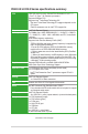
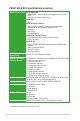
P8H61-M LX R2.0 Series specifications summary CPU Chipset Memory Graphics Expansion slots Storage LAN Audio USB Rear panel ports LGA1155 socket for Intel® Second/Third Generation Core™ i7 / Core™ i5 / Core™ i3/ Pentium® processors Supports 32/22nm CPU Supports Intel® Turbo Boost Technology 2.0* *The Intel® Turbo Boost Technology 2.0 suppport depends on the CPU types. **Refer to www.asus.com for Intel® CPU support list. Intel® H61 Express Chipset 2 x DIMMs, max. 16GB, DDR3 2200(O.C.) / 2133(O.C.
P8H61-M LX R2.
Chapter 1 Product introduction 1.1 Welcome! Thank you for buying an ASUS® P8H61-M LX R2.0 Series motherboard! The motherboard delivers a host of new features and the latest technologies, making it another standout in the long line of ASUS quality motherboards! Before you start installing the motherboard and adding components, check the items in your package with the list below. 1.2 Package contents Check your motherboard package for the following items. Motherboard ASUS P8H61-M LX 2.
Intel® H61 Express Chipset The Intel® H61 Express Chipset is the latest single-chipset design to support the new 1155 socket Intel® Core™ i7 / Core™ i5 / Core™ i3 second generation processors. It provides improved performance by utilizing serial point-to-point links, which allows increased bandwidth and stability. Dual-Channel DDR3 2200(O.C.) / 2133 (O.C.) / 2000 (O.C.) / 1866 (O.C.) / 1600 / 1333 / 1066MHz support The motherboard supports DDR3 memory that features data transfer rates of 2200 (O.C.
100% All High-quality Conductive Polymer Capacitors (P8H61-M LX R2.0 PLUS R2.0 only) This motherboard uses all high-quality conductive polymer capacitors for durability, improved lifespan, and enhanced thermal capacity. 1.3.2 ASUS DIGI+VRM Digital Power Control: Digital Power Design for the CPU and iGPU All-new digital CPU power controls work perfectly together to match digital power signal (SVID) requests from the CPU, with ultra-fast sensing and response efficiently delivering precision power.
ASUS Anti-Surge Protection This special design prevents expensive devices and the motherboard from damage caused by power surges from switching power supply (PSU). AI Suite II With its fast user-friendly interface, ASUS AI Suite II consolidates all the exclusive ASUS features into one simple to use software package. It allows you to supervise overclocking, energy management, fan speed control, and voltage and sensor readings.
ASUS CrashFree BIOS 3 ASUS CrashFree BIOS 3 is an auto-recovery tool that allows you to restore a corrupted BIOS file using the bundled support DVD or USB flash disk that contains the latest BIOS file. ASUS EZ Flash 2 ASUS EZ Flash 2 is a utility that allows you to update the BIOS without using an OS-based utility. C.P.R. (CPU Parameter Recall) The BIOS C.P.R. feature automatically restores the CPU default settings when the system hangs due to overclocking failure. C.P.R.
1.4 Before you proceed Take note of the following precautions before you install motherboard components or change any motherboard settings. • Unplug the power cord from the wall socket before touching any component. • Before handling components, use a grounded wrist strap or touch a safely grounded object or a metal object, such as the power supply case, to avoid damaging them due to static electricity. • Hold components by the edges to avoid touching the ICs on them.
1.5 Motherboard overview Study the configuration of your chassis to ensure that the motherboard fits before installing the motherboard. Ensure that you unplug the power cord before installing or removing the motherboard. Failure to do so can cause you physical injury and damage motherboard components. 1.5.1 Placement direction 1.5.2 Screw holes When installing the motherboard, ensure that you place it into the chassis in the correct orientation.
1.5.3 Motherboard layout 1 2 3 1 4 18.3cm(7.2in) KBMS CPU_FAN COM DIGI +VRM RTL 8111E/ 8111F EATXPWR LAN1_USB12 Lithium Cell CMOS Power CHA_FAN AUDIO 24.4cm(9.6in) LGA1155 USB34 DDR3 DIMM_B1 (64bit, 240-pin module) VGA LPT DDR3 DIMM_A1 (64bit, 240-pin module) ATX12V 2 PCIEX16 P8H61-M LX R2.
1.6 Central Processing Unit (CPU) The motherboard comes with a surface mount LGA1155 socket designed for the Intel® Second Generation Core™ i7 / Core™ i5 / Core™ i3 processors. P8H61-M LX R2.0 P8H61-M LX R2.0 CPU socket LGA1155 Unplug all power cables before installing the CPU. • Upon purchase of the motherboard, ensure that the PnP cap is on the socket and the socket contacts are not bent.
1.6.1 Installing the CPU To install a CPU: 1. Locate the CPU socket on the motherboard. P8H61-M LX R2.0 P8H61-M LX R2.0 CPU socket LGA1155 2. Press the load lever with your thumb (A), and then move it to the right (B) until it is released from the retention tab. Load lever A To prevent damage to the socket pins, do not remove the PnP cap unless you are installing a CPU. B Retention tab 3. Lift the load lever in the direction of the arrow until the load plate is completely lifted.
4. Remove the PnP cap from the CPU socket by lifting the tab only. PnP cap 5. Position the CPU over the socket, ensuring that the gold triangle is on the bottom‑left corner of the socket, and then fit the socket alignment keys into the CPU notches. The CPU fits in only one correct orientation. DO NOT force the CPU into the socket to prevent bending the connectors on the socket and damaging the CPU! CPU notches Gold triangle mark Alignment keys 6.
7. Close the load plate (A), and then push down the load lever (B), ensuring that the front edge of the load plate slides under the retention knob (C). B A C 8. 1-12 Insert the load lever under the retention tab. ASUS P8H61-M LX R2.
1.6.2 Installing the CPU heatsink and fan The Intel® LGA1155 processor requires a specially designed heatsink and fan assembly to ensure optimum thermal condition and performance. • When you buy a boxed Intel® processor, the package includes the CPU fan and heatsink assembly. If you buy a CPU separately, ensure that you use only Intel®‑certified multi‑directional heatsink and fan. • Your Intel® LGA1155 heatsink and fan assembly comes in a push-pin design and requires no tool to install.
3. Connect the CPU fan cable to the connector on the motherboard labeled CPU_FAN. CPU FAN PWM CPU FAN IN CPU FAN PWR GND CPU_FAN P8H61-M LX R2.0 P8H61-M LX R2.0 CPU fan connector Do not forget to connect the CPU fan connector! Hardware monitoring errors can occur if you fail to plug this connector. 1.6.3 Uninstalling the CPU heatsink and fan To uninstall the CPU heatsink and fan: 1. Disconnect the CPU fan cable from the connector on the motherboard. 2. Rotate each fastener counterclockwise.
4. Carefully remove the heatsink and fan assembly from the motherboard. 5. Rotate each fastener clockwise to ensure correct orientation when reinstalling. 1.7 System memory 1.7.1 Overview DIMM_A1 DIMM_B1 The motherboard comes with two Double Data Rate 3 (DDR3) Dual Inline Memory Modules (DIMM) sockets. A DDR3 module has the same physical dimensions as a DDR2 DIMM but is notched differently to prevent installation on a DDR2 DIMM socket.
1.7.2 Memory configurations You may install 1GB, 2GB, 4GB, and 8GB unbuffered non‑ECC DDR3 DIMMs into the DIMM sockets. • You may install varying memory sizes in Channel A and Channel B. The system maps the total size of the lower-sized channel for the dual-channel configuration. Any excess memory from the higher-sized channel is then mapped for single-channel operation. • According to Intel CPU specification, DIMM voltage below 1.65V is recommended to protect the CPU.
P8H61-M LX R2.0 Series Motherboard Qualified Vendors Lists (QVL) DDR3-2400 MHz capability Vendors Part No. Size SS/ DS Chip Brand Chip NO. Timing Voltage CORSAIR G.SKILL G.SKILL GEIL KINGMAX Transcend Transcend Transcend CMGTX8(XMP) F3-19200CL11Q-16GBZHD(XMP1.
DDR3-2000 MHz capability Vendors Part No. Size SS/ DS Chip Brand Chip NO. Timing Apacer CORSAIR G.SKILL G.SKILL G.SKILL GEIL KINGSTON KINGSTON KINGSTON KINGSTON KINGSTON Transcend Asint 78.AAGD5.
DDR3-1600 MHz capability Vendors Part No. Size SS/ DS Chip Brand - • • - • • 9-9-9-24 7-9-7-21 8-8-8-24 8-8-8-24 9-9-9-24 7-8-7-20 9-9-9-24 9-9-9-24 8-8-8-24 8-8-8-24 9-9-9-24 9-9-9-24 9-9-9-24 9-9-9-24 7-7-7-24 7-8-7-24 8-8-8-24 9-9-9-24 9-9-9-24 7-8-7-24 8-8-8-24 9-9-9-24 9-9-9-28 1.55V-1.75V 1.55V-1.75V 1.65V 1.65V 1.65V 1.65V 1.65V 1.65V 1.65V 1.65V 1.65V 1.65V 1.65V 1.5V 1.6V 1.6V 1.60V 1.5V 1.5V~1.6V 1.6V XMP 1.35V 1.5V 1.
DDR3-1333 MHz capability Vendors Part No. Size SS/ Chip DS Brand Chip NO. Timing Voltage SS A-Data AD30908C8D-151C E0906 AD30908C8D-151C E0903 AM5D5808DEWSBG AM5D5808FEQSBG 9FF22D9KPT 9KF27D9KPT - - A-Data AD31333001GOU 1GB A-Data AD31333G001GOU 3GB(3 x 1GB) SS - A-Data AD31333002GOU 2GB DS A-Data A-Data Apacer Apacer CORSAIR CORSAIR CORSAIR CORSAIR CORSAIR CORSAIR CORSAIR Crucial Crucial Crucial AD31333G002GMU 78.A1GC6.9L1 78.A1GC6.
DDR3-1333 MHz capability 8-8-8-20 9-9-9-20 9-9-9-20 8-8-8-24 8-8-8-24 9 9 9-9-9-24 7-7-7-20 - DIMM socket support Voltage (Optional) 1 DIMM 2 DIMMs 1.60V • • 1.65V • • 1.65V • • 1.5V • • • • 1.5V • • • • • • • • • • • • • • • • 1.
DDR3-1066 MHz capability Vendors Part No. Size SS/ Chip Brand Chip NO. DS Timing Crucial Crucial CT12864BA1067.8FF CT25664BA1067.
1.7.3 Installing a DIMM Unplug the power supply before adding or removing DIMMs or other system components. Failure to do so can cause severe damage to both the motherboard and the components. 1. Press the retaining clips outward to unlock a DIMM socket. 2. Align a DIMM on the socket such that the notch on the DIMM matches the DIMM slot key on the socket. 2 DIMM notch 1 1 DIMM slot key Unlocked retaining clip A DIMM is keyed with a notch so that it fits in only one direction.
1.8 Expansion slots In the future, you may need to install expansion cards. The following sub‑sections describe the slots and the expansion cards that they support. Unplug the power cord before adding or removing expansion cards. Failure to do so may cause you physical injury and damage motherboard components. 1.8.1 Installing an expansion card To install an expansion card: 1.
1.9 Jumpers Clear RTC RAM (3-pin CLRTC) This jumper allows you to clear the Real Time Clock (RTC) RAM in CMOS. You can clear the CMOS memory of date, time, and system setup parameters by erasing the CMOS RTC RAM data. The onboard cell battery powers the RAM data in CMOS, which include system setup information such as system passwords. CLRTC P8H61-M LX R2.0 1 2 2 Normal (Default) Clear RTC 3 P8H61-M LX R2.0 Clear RTC RAM To erase the RTC RAM: 1. Turn OFF the computer and unplug the power cord.
1.10 Connectors 1.10.1 Rear panel connectors 1 2 11 3 10 9 8 4 5 7 6 1. PS/2 Mouse (Green). This port is for a PS/2 mouse. 2. Parallel port. This 25-pin port connects a parallel printer, a scanner, or other device. 3. LAN (RJ-45) port. This port allows Gigabit connection to a Local Area Network (LAN). Refer to the table below for the LAN port LED indications.
Use a chassis with an HD audio module in the front panel to support 8-channel audio output. 7. USB 2.0 ports 1 and 2. These two 4-pin Universal Serial Bus (USB) ports are for USB 2.0/1.1 devices. 8. USB 2.0 ports 3 and 4. These two 4-pin Universal Serial Bus (USB) ports are for USB 2.0/1.1 devices. 9. Video Graphics Adapter (VGA) port. This 15-pin port is for a VGA monitor or other VGA-compatible hardware. 10. Serial port. This 9-pin COM1 port is for pointing devices or other serial devices.
2. ATX power connectors (24-pin EATXPWR, 4-pin ATX12V) These connectors are for ATX power supply plugs. The power supply plugs are designed to fit these connectors in only one orientation. Find the proper orientation and push down firmly until the connectors completely fit. GND GND +12V DC +12V DC EATX12V P8H61-M LX R2.
4. CPU and chassis fan connectors (4-pin CPU_FAN, 3-pin CHA_FAN) Connect the fan cables to the fan connectors on the motherboard, ensuring that the black wire of each cable matches the ground pin of the connector. CPU FAN PWM CPU FAN IN CPU FAN PWR GND CPU_FAN CHA_FAN Rotation +12V GND P8H61-M LX R2.0 P8H61-M LX R2.0 Fan connectors Do not forget to connect the fan cables to the fan connectors. Insufficient air flow inside the system may damage the motherboard components.
Intel® H61 Serial ATA 3.0Gb/s connectors (7-pin SATA3G_1~4) These connectors connect to Serial ATA 3.0 Gb/s hard disk drives and optical drives via Serial ATA 3.0 Gb/s signal cables. GND RSATA_TXP1 RSATA_TXN1 GND RSATA_RXN1 RSATA_RXP1 GND SATA3G_4 SATA3G_3 GND RSATA_RXP3 RSATA_RXN3 GND RSATA_TXN3 RSATA_TXP3 GND SATA3G_1 GND RSATA_TXP2 RSATA_TXN2 GND RSATA_RXN2 RSATA_RXP2 GND P8H61-M LX R2.0 SATA3G_2 GND RSATA_RXP4 RSATA_RXN4 GND RSATA_TXN4 RSATA_TXP4 GND 6. P8H61-M LX R2.0 Intel® SATA 3.
8. System panel connector (10-1 pin PANEL) This connector supports several chassis-mounted functions. F_PANEL P8H61-M LX R2.0 PIN 1 HD_LED+ HD_LEDGround Reset PLED+ PLEDPWR GND PWR LED PWR BTN +HD_LED RESET P8H61-M LX R2.0 System panel connector • • • • System power LED (2-pin PLED) This 2-pin connector is for the system power LED. Connect the chassis power LED cable to this connector.
1.11 Software support 1.11.1 Installing an operating system This motherboard supports Windows® XP / Vista / 7 Operating Systems (OS). Always install the latest OS version and corresponding updates to maximize the features of your hardware. • Motherboard settings and hardware options vary. Refer to your OS documentation for detailed information.
Chapter 2 BIOS information 2.1 Managing and updating your BIOS Save a copy of the original motherboard BIOS file to a USB flash disk in case you need to restore the BIOS in the future. Copy the original motherboard BIOS using the ASUS Update utility. 2.1.1 ASUS Update utility The ASUS Update is a utility that allows you to manage, save, and update the motherboard BIOS in a Windows® environment.
The ASUS Update utility is capable of updating itself through the Internet. Always update the utility to avail all its features. Updating from a BIOS file a. Select Update BIOS from file, then click Next. b. Locate the BIOS file from the Open window, then click Open. 3. Follow the onscreen instructions to complete the updating process. 2.1.2 ASUS EZ Flash 2 The ASUS EZ Flash 2 feature allows you to update the BIOS without using an OS‑based utility.
3. 4. 5. 6. Press to switch to the Drive field. Press the Up/Down arrow keys to find the USB flash disk that contains the latest BIOS, and then press . Press to switch to the Folder Info field. Press the Up/Down arrow keys to find the BIOS file, and then press to perform the BIOS update process. Reboot the system when the update process is done. • This function supports USB flash disks formatted using FAT32/ FAT16 on a single partition.
2.1.4 ASUS BIOS Updater The ASUS BIOS Updater allows you to update the BIOS in a DOS environment. This utility also allows you to copy the current BIOS file as a backup when the BIOS fails or gets corrupted during the updating process. The succeeding utility screens are for reference only. The actual utility screens may not be the same as shown here. Before updating BIOS 1. 2. Prepare the motherboard support DVD and a USB flash drive formatted using FAT32/ FAT16 on a single partition.
Updating the BIOS file To update the BIOS file using BIOS Updater 1. At the FreeDOS prompt, type bupdater /pc /g and press . D:\>bupdater /pc /g 2. The BIOS Updater screen appears as below. ASUSTek BIOS Updater for DOS V1.18 Current ROM BOARD: P8H61-M LX R2.0 VER: 0206 DATE: 05/16/2011 Update ROM BOARD: Unknown VER: Unknown DATE: Unknown PATH: A:\ H61MLXR2.CAP A: Note [Enter] Select or Load [Up/Down/Home/End] Move 3.
2.2 BIOS setup program Use the BIOS Setup program to update the BIOS or configure its settings. The BIOS screens include navigation keys and a brief online help to guide you in using the BIOS Setup program. Entering BIOS Setup at startup To enter BIOS Setup at startup: • Press during the Power-On Self Test (POST). If you do not press , POST continues with its routines. Entering BIOS Setup after POST To enter BIOS Setup after POST: • Press ++ simultaneously.
BIOS menu screen The BIOS setup program can be used under two modes: EZ Mode and Advanced Mode. You can change modes by pressing F7 or through the Exit/Advanced Mode button in the EZ Mode/Advanced Mode screen. EZ Mode By default, the EZ Mode screen appears when you enter the BIOS setup program. The EZ Mode provides you an overview of the basic system information, and allows you to select the display language, system performance mode and boot device priority.
Advanced Mode The Advanced Mode provides advanced options for experienced end-users to configure the BIOS settings. The figure below shows an example of the Advanced Mode. Refer to the following sections for the detailed configurations. To access the EZ Mode, click Exit, then select ASUS EZ Mode.
Menu items The highlighted item on the menu bar displays the specific items for that menu. For example, selecting Main shows the Main menu items. The other items (Ai Tweaker, Advanced, Monitor, Boot, Tool, and Exit) on the menu bar have their respective menu items. Submenu items A greater than sign (>) before each item on any menu screen means that the item has a submenu. To display the submenu, select the item and press .
2.3 Main menu The Main menu screen appears when you enter the Advanced Mode of the BIOS Setup program. The Main menu provides you an overview of the basic system information, and allows you to set the system date, time, language, and security settings. 2.3.1 System Language [English] 2.3.2 System Date [Day xx/xx/xxxx] 2.3.3 System Time [xx:xx:xx] 2.3.4 Security Allows you to choose the BIOS language version from the options. Configuration options: [English] Allows you to set the system date.
Administrator Password If you have set an administrator password, we recommend that you enter the administrator password for accessing the system. Otherwise, you might be able to see or change only selected fields in the BIOS setup program. To set an administrator password: 1. Select Security and press . 3. In the pop-up window, enter a password. Confirm the password when prompted. 2. Select Administrator Password, then press . To change an administrator password: 1. 2. 3. 4.
To set a user password: 1. Select the User Password item and press . 3. Confirm the password when prompted. 2. From the Create New Password box, key in a password, then press . To change a user password: 1. 2. 3. 4. Select the User Password item and press . From the Enter Current Password box, key in the current password, then press . From the Create New Password box, key in a new password, then press . Confirm the password when prompted.
2.4 Ai Tweaker menu The Ai Tweaker menu items allow you to configure overclocking-related items. Be cautious when changing the settings of the Ai Tweaker menu items. Incorrect field values can cause the system to malfunction. The configuration options for this section vary depending on the CPU and DIMM model you installed on the motherboard.
2.4.1 Memory Frequency [Auto] Allows you to set the memory operating frequency. Configuration options: [Auto] [DDR3800MHz] [DDR3-1066MHz] [DDR3-1333MHz] Selecting a very high memory frequency may cause the system to become unstable! If this happens, revert to the default setting. 2.4.2 EPU Power Saving Mode [Disabled] Allows you to enable or disable the EPU power saving function.
The following three items appear only when you set both the Enhanced Intel® SpeedStep Technology and Turbo Mode items to [Enabled]. Long Duration Power Limit [Auto] Use <+>/<-> to adjust the value. Long Duration Maintained [Auto] Use <+>/<-> to adjust the value. Short Duration Power Limit [Auto] Use <+>/<-> to adjust the value. Primary Plane Current Limit [Auto] Use <+>/<-> to adjust the value. Secondary Plane Current Limit [Auto] Use <+>/<-> to adjust the value. 2.4.
CPU Fixed Frequency [xxx] Frequency switching affects the VRM transient response and the thermal component. Higher frequency gets quicker transient response. Use the <+> and <-> keys to adjust the value. The values range from 200k Hz to 350k Hz with a 50k Hz interval. DO NOT remove the thermal module when switching to Manual Mode. The thermal conditions should be monitored. CPU Power Phase Control [Standard] Allows you to control the power phase based on the CPU’s demands.
2.4.7 CPU Voltage [Offset Mode] [Manual Mode] Allows you to set a fixed CPU voltage. [Offset Mode] Allows you to set the Offset voltage. 2.4.8 Offset Mode Sign [+] This item appears only when you set the CPU Voltage item to [Offset Mode]. [+] [–] To offset the voltage by a positive value. To offset the voltage by a negative value. CPU Offset Voltage [Auto] This item appears only when you set the CPU Voltage item to [Offset Mode] and allows you to set the Offset voltage.
• The values of the CPU Manual Voltage, CPU Offset Voltage, iGPU Manual Voltage, iGPU Offset Voltage, DRAM Voltage, VCCSA Voltage and PCH Voltage items are labeled in different color, indicating the risk levels of high voltage settings. • The system may need better cooling system to work stably under high voltage settings. 2.4.14 CPU PLL Voltage [Auto] 2.5 Advanced menu Allows you to set the CPU and PCH PLL voltage. The values range from 1.80V to 1.90V with a 0.1V interval.
CPU Ratio [Auto] Allows you to set the ratio between the CPU Core Clock and the BCLK Frequency. Use <+> and <-> keys or the numeric keypad to adjust the ratio. The valid value ranges vary according to your CPU model. Intel Adaptive Thermal Monitor [Enabled] [Enabled] [Disabled] Enables the overheated CPU to throttle its clock speed to cool down. Disables the CPU thermal monitor function. Active Processor Cores [All] Allows you to choose the number of CPU cores to activate in each processor package.
CPU C6 Report [Auto] Allows you to disable or enable the CPU C6 report to the operating system. Configuration options: [Enabled] [Disabled] Intel Virtualization Technology [Disabled] [Enabled] [Disabled] 2.5.2 Allows a hardware platform to run multiple operating systems separately and simultaneously, enabling one system to virtually function as several systems. Disables this function. PCH Configuration High Precision Timer [Enabled] Allows you to enable or disable the High Precision Event Timer.
2.5.3 SATA Configuration While entering Setup, the BIOS automatically detects the presence of SATA devices. The SATA Port items show Not Present if no SATA device is installed to the corresponding SATA port. SATA Mode Selection [IDE Mode] Allows you to set the SATA configuration. [Disabled] Disables the SATA function. [IDE Mode] Set to [IDE Mode] when you want to use the Serial ATA hard disk drives as Parallel ATA physical storage devices.
2.5.4 System Agent Configuration Memory Remap Feature [Enabled] [Enabled] [Disabled] Allow you to enable remapping the memory above 4GB. Disables this function. Graphics Configuration Primary Display [Auto] Allows you to select a primary display from IGFX or PEG graphic devices. Configuration options: [Auto] [IGFX] [PEG] iGPU Memory [64M] Allows you to set the iGPU memory size.
2.5.5 USB Configuration The items in this menu allow you to change the USB-related features. The USB Devices item shows the auto-detected values. If no USB device is detected, the item shows None. Legacy USB Support [Enabled] [Enabled] [Disabled] [Auto] Enables the support for USB devices on legacy operating systems (OS). The USB devices can be used only for the BIOS setup program. Allows the system to detect the presence of USB devices at startup.
Serial Port Configuration The sub-items in this menu allow you to set the serial port configuration. Serial Port [Enabled] Allows you to enable or disable the serial port (COM). Configuration options: [Enabled] [Disabled] Change Settings [IO=3F8h; IRQ=4] Allows you to select the Serial Port base address. Configuration options: [IO=3F8h; IRQ=4] [IO=2F8h; IRQ=3] [IO=3E8h; IRQ=4] [IO=2E8h; IRQ=3] Parallel Port Configuration The sub-items in this menu allow you to set the parallel port configuration.
Power On By PS/2 Keyboard [Disabled] [Disabled] [Space Bar] [Ctrl-Esc] [Power Key] Disables the Power On by a PS/2 keyboard. Sets the Space Bar on the PS/2 keyboard to turn on the system. Sets the Ctrl+Esc key on the PS/2 keyboard to turn on the system. Sets Power key on the PS/2 keyboard to turn on the system. This feature requires an ATX power supply that provides at least 1A on the +5VSB lead. Power On By PS/2 Mouse [Disabled] [Disabled] [Enabled] Disables the Power On by a PS/2 mouse.
2.6 Monitor menu The Monitor menu displays the system temperature/power status, and allows you to change the fan settings. 2.6.1 CPU Temperature / MB Temperature ������������� [xxxºC/xxxºF] 2.6.2 CPU / Chassis Fan Speed [xxxx RPM] or [Ignore] / [N/A] 2.6.3 CPU Q-Fan Control [Enabled] The onboard hardware monitor automatically detects and displays the CPU and motherboard temperatures. Select Ignore if you do not wish to display the detected temperatures.
2.6.4 CPU Fan Speed Low Limit [200 RPM] This item appears only when you enable the CPU Q-Fan Control feature and allows you to disable or set the CPU fan warning speed. Configuration options: [Ignore] [200 RPM] [300 RPM] [400 RPM] [500 RPM] [600 RPM] CPU Fan Profile [Standard] This item appears only when you enable the CPU Q-Fan Control feature and allows you to set the appropriate performance level of the CPU fan.
2.7 Boot menu The Boot menu items allow you to change the system boot options. 2.7.1 Bootup NumLock State [On] 2.7.2 Full Screen Logo [Enabled] [On] [Off] [Enabled] [Disabled] Sets the power-on state of the NumLock to [On]. Sets the power-on state of the NumLock to [Off]. Enables the full screen logo display feature. Disables the full screen logo display feature. Set this item to [Enabled] to use the ASUS MyLogo 2™ feature.
2.7.4 Option ROM Messages [Force BIOS] 2.7.5 Setup Mode [EZ Mode] 2.7.6 UEFI/Legacy Boot [Enable both UEFI and Legacy] [Force BIOS] The third-party ROM messages will be forced to display during the boot sequence. [Keep Current] The third-party ROM messages will be displayed only if the third-party manufacturer had set the add-on device to do so. [Advanced Mode] Sets Advanced Mode as the default screen for entering the BIOS setup program.
2.8 Tools menu The Tools menu items allow you to configure options for special functions. Select an item then press to display the submenu. 2.8.1 ASUS EZ Flash Utility Allows you to run ASUS EZ Flash 2. Press [Enter] to launch the ASUS EZ Flash 2 screen. For more details, see section 2.1.2 ASUS EZ Flash 2. 2.8.2 ASUS SPD Information DIMM Slot # [Slot 1] Displays the Serial Presence Detect (SPD) information of the DIMM module installed on the selected slot.
2.9 Exit menu The Exit menu items allow you to load the optimal default values for the BIOS items, and save or discard your changes to the BIOS items. You can access the EZ Mode from the Exit menu. Load Optimized Defaults This option allows you to load the default values for each of the parameters on the Setup menus. When you select this option or if you press , a confirmation window appears. Select Yes to load the default values.
2-32 ASUS P8H61-M LX R2.
Appendices Notices Federal Communications Commission Statement This device complies with Part 15 of the FCC Rules. Operation is subject to the following two conditions: • This device may not cause harmful interference. • This device must accept any interference received including interference that may cause undesired operation. This equipment has been tested and found to comply with the limits for a Class B digital device, pursuant to Part 15 of the FCC Rules.
Canadian Department of Communications Statement This digital apparatus does not exceed the Class B limits for radio noise emissions from digital apparatus set out in the Radio Interference Regulations of the Canadian Department of Communications. This class B digital apparatus complies with Canadian ICES-003.
ASUS contact information ASUSTeK COMPUTER INC. Address Telephone Fax E-mail Web site Technical Support Telephone Online support 15 Li-Te Road, Peitou, Taipei, Taiwan 11259 +886-2-2894-3447 +886-2-2890-7798 info@asus.com.tw www.asus.com.tw +86-21-38429911 support.asus.
A-4 ASUS P8H61-M LX R2.0 (510)739-3777/(510)608-4555 800 Corporate Way, Fremont, CA 94539. Asus Computer International Signature : Date : Representative Person’s Name : Apr. 13, 2012 Steve Chang / President This device complies with part 15 of the FCC Rules. Operation is subject to the following two conditions: (1) This device may not cause harmful interference, and (2) this device must accept any interference received, including interference that may cause undesired operation.