Carte mère P8H77-M PRO
F7508 Seconde édition Juin 2012 Copyright © 2012 ASUSTeK COMPUTER INC. Tous droits réservés. Aucun extrait de ce manuel, incluant les produits et logiciels qui y sont décrits, ne peut être reproduit, transmis, transcrit, stocké dans un système de restitution, ou traduit dans quelque langue que ce soit sous quelque forme ou quelque moyen que ce soit, à l’exception de la documentation conservée par l’acheteur dans un but de sauvegarde, sans la permission écrite expresse de ASUSTeK COMPUTER INC. (“ASUS”).
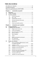
Table des matières Informations sur la sécurité....................................................................... vii À propos de ce manuel............................................................................. viii Résumé des spécifications de la P8H77-M PRO....................................... x Chapitre 1 : Introduction au produit 1.1 Bienvenue !.................................................................................... 1-1 1.2 Contenu de la boîte...........................
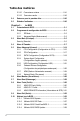
Table des matières 2.3.10 Connecteurs arrières..................................................... 2-41 2.3.12 Connexions audio.......................................................... 2-43 2.4 Démarrer pour la première fois.................................................. 2-45 2.5 Eteindre l’ordinateur................................................................... 2-45 Chapitre 3 : Le BIOS 3.1 Présentation du BIOS...................................................................
Table des matières Chapitre 4 : Support logiciel 4.1 Installer un système d’exploitation............................................. 4-1 4.2 Informations sur le DVD de support............................................ 4-1 4.3 4.4 4.2.1 Lancer le DVD de support................................................ 4-1 4.2.2 Obtenir les manuels des logiciels.................................... 4-2 Informations sur les logiciels...................................................... 4-3 4.3.
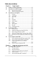
5.2 Technologie LucidLogix® Virtu™ MVP........................................ 5-4 5.2.1 Installation du matériel..................................................... 5-4 5.2.2 Configuration du matériel................................................. 5-5 5.2.3 Configuration du logiciel................................................... 5-6 Appendice Notices........................................................................................................
Informations sur la sécurité Sécurité électrique • Pour éviter tout risque de choc électrique, débranchez le câble d’alimentation de la prise de courant avant de toucher au système. • Lorsque vous ajoutez ou enlevez des composants, vérifiez que les câbles d’alimentation sont débranchés avant de relier les câbles de signal. Si possible, déconnectez tous les câbles d’alimentation du système avant d’ajouter un périphérique.
À propos de ce manuel Ce guide de l’utilisateur contient les informations dont vous aurez besoin pour installer et configurer la carte mère. Comment ce manuel est organisé Ce manuel contient les parties suivantes : • Chapitre 1 : Introduction au produit Ce chapitre décrit les fonctions de la carte mère et les technologies qu’elle supporte.
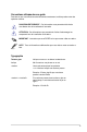
Conventions utilisées dans ce guide Pour être sûr que vous effectuiez certaines tâches correctement, veuillez prendre notes des symboles suivants. DANGER/AVERTISSEMENT : Ces informations vous permettront d’éviter de vous blesser lors de la réalisation d’une tâche. ATTENTION : Ces informations vous permettront d’éviter d’endommager les composants lors de la réalisation d’une tâche. IMPORTANT : Instructions que vous DEVEZ suivre pour mener à bien une tâche.
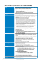
Résumé des spécifications de la P8H77-M PRO CPU Chipset Mémoire Intel® H77 Express Chipset 4 x slots DIMM, max. 32 Go*, DDR3 2200** (O.C) / 2133 (O.C) / 2000 (O.C) / 1866 (O.C.) / 1600 / 1333 / 1066 MHz, non-ECC et non tamponnée Architecture mémoire Dual-Channel (bi-canal) Support Intel® Extreme Memory Profile (XMP) * Selon les spécifications d’Intel®, la capacité mémoire maximum de 32Go peut être atteinte avec des modules mémoire de 8Go ou plus.
Résumé des spécifications de la P8H77-M PRO Audio CODEC High Definition Audio Realtek® ALC892 8 canaux - Absolute Pitch 192khz/24bit True BD Lossless Sound - Protection de la couche audio des disques BD-ROM - Supporte la détection et la réaffectation (en façade uniquement) des jacks audio et la multi-diffusion des flux audio - Ports de sortie S/PDIF optique sur le panneau d’E/S Fonctions d’overclocking Precision Tweaker 2 : - vCore : voltage CPU ajustable par incréments de 0.
Résumé des spécifications de la P8H77-M PRO USB Intel® H77 Express Chipset supportant le standard UASP* - 2 x ports USB 3.0 sur le panneau arrière (bleus) - 2 x ports USB 3.0 à mi-carte (bleus) pour la prise en charge de ports USB 3.0 en façade de châssis Intel® H77 Express Chipset - 10 x ports USB 2.0 (6 ports à mi-carte + 4 ports sur le panneau d’E/S) * En raison de certaines limitations du chipset Intel®, les ports USB 3.
Chapitre 1 Chapitre 1 : 1.1 Introduction au produit Bienvenue ! Merci d’avoir acheté une carte mère ASUS® P8H77-M PRO ! La carte mère offre les technologies les plus récentes associées à des fonctionnalités nouvelles qui en font un nouveau digne représentant de la qualité des cartes mères ASUS ! Avant de commencer à installer la carte mère, vérifiez le contenu de la boîte grâce à la liste ci-dessous. 1.
1.3 Fonctions spéciales 1.3.1 Points forts du produit Chapitre 1 Compatible avec les processeurs de seconde et troisième génération Intel® Core™ i7 / Core™ i5 / Core™ i3 / Pentium® / Celeron® au format LGA1155 Cette carte mère est compatible avec les derniers processeurs Intel® Core™ i7 / Core™ i5 / Core™ i3 / Pentium® / Celeron® au format LGA1155, intégrant un contrôleur mémoire et PCI Express pour permettre le support de 2 canaux (4 DIMM) de modules DDR3 et 16 voies PCI Express 2.
Prise en charge de contrôleur réseau Gigabit Chapitre 1 La carte mère intègre un contrôleur réseau Gigabit. Celui-ci supporte une fonction de gestion ACPI pour offrir une solution de gestion de l’alimentation efficace pour les systèmes d’exploitation avancés. Support de sortie S/PDIF La technologie S/PDIF (SONY-PHILIPS Digital Interface) est à même de transformer votre ordinateur en un système audio haut de gamme doté d’une connectivité numérique idéale pour ressortir sur un système audio externe.
1.3.3 Fonctionnalités exclusives GPU Boost Chapitre 1 GPU Boost améliore les performances graphique du GPU dédié. Son interface conviviale facilite la fléxibilité du réglage des fréquences d’opération et fournit des mises à niveau stables du système quel que soit vos besoins. USB 3.0 Boost La technologie ASUS USB 3.0 Boost supporte le protocole UASP (USB Attached SCSI Protocol), le tout dernier standard USB 3.0. Avec USB 3.
1.3.4 Solutions thermiques silencieuses Fan Xpert Chapitre 1 La fonction ASUS Fan Xpert permet aux utilisateurs d’ajuster intelligemment la vitesse des ventilateurs du CPU et du châssis en fonction de la température ambiante résultant des conditions thermiques des différents composant et en fonction de la charge du système. Une variété de profils pratiques apporte une grande flexibilité au contrôle de la vitesse des ventilateurs dans le but d’obtenir un environnement frais et silencieux.
ASUS EZ-Flash 2 Chapitre 1 ASUS EZ Flash 2 est utilitaire de mise à jour du BIOS convivial. Pressez simplement les raccourcis claviers pré-définis pour lancer l’utilitaire et mettre à jour le BIOS sans avoir à charger le système d’exploitation. 1.3.6 Autres fonctionnalités spéciales LucidLogix® Virtu MVP La technologie LucidLogix Virtu MVP, comprenant les fonctionnalités HyperFormance™ et Virtual Vsync™, permet d’améliorer les performances des cartes graphiques installées jusqu’à 30%.
Chapitre 2 2.1 Avant de commencer Suivez les précautions ci-dessous avant d’installer la carte mère ou d’en modifier les paramètres. • Débranchez le câble d’alimentation de la prise murale avant de toucher les composants. • Utilisez un bracelet antistatique ou touchez un objet métallique relié au sol (comme l’alimentation) pour vous décharger de toute électricité statique avant de toucher aux composants. • Tenez les composants par les coins pour éviter de toucher les circuits imprimés.
2.2 Vue générale de la carte mère 2.2.1 Diagramme de la carte mère 1 2 3 4 5 1 6 24.4cm(9.6in) GPU_Boost KB_USB3_34 ASM 1442 7 8 MemOK! DRAM_LED EATXPWR 2 CHA_FAN1 PWR_FAN 10 Lithium Cell CMOS Power AUDIO 24.4cm(9.
Contenu du diagramme Connecteurs/Interrupteur/Boutons/LED/Jumper Page 1. Connecteurs de ventilation (4-pin CPU_FAN, 4-pin CHA_FAN, 3-pin PWR_FAN) 2-24 2. Connecteurs d’alimentation (24-pin EATXPWR, 8-pin EATX12V) 2-25 3. Interrupteur GPU Boost 2-16 4. LED GPU Boost 2-18 5. Interface de connexion pour processeur Intel® 2-4 6. Interfaces de connexion pour modules mémoire DDR3 2-5 7. Bouton MemOK! 2-15 8. LED DRAM 2-17 9. Connecteur USB 3.0 (20-1 pin USB3_34) 2-22 10.
2.2.3 Central Processing Unit (CPU) La carte mère est livrée avec un socket LGA1155 conçu pour l’installation d’un processeur de seconde/troisième génération Intel® Core™ i7 / Core™ i5 / Core™ i3 / Pentium™ / Celeron™. P8H77-M PRO Chapitre 2 P8H77-M CPU socket Socket 1155PRO de la P8H77-M PRO LGA1155 Assurez-vous que tous les câbles soient débranchés lors de l’installation du CPU. • Les processeurs au format LGA1156 sont incompatibles avec les sockets LGA1155.
2.2.4 Mémoire système La carte mère est livrée avec quatre sockets pour l’installation de modules mémoire Double Data Rate 3 (DDR3). DIMM_B1 DIMM_B2 DIMM_A1 DIMM_A2 Un module DDR3 possède les même dimensions physiques qu’un module DDR2 mais s’encoche différemment pour éviter son installation sur des sockets DDR ou DDR2. NE PAS installer de module mémoire DDR ou DDR2 sur les slots DDR3.
Configurations mémoire Vous pouvez installer des modules mémoire DDR3 non taponnée et non ECC de 1 Go, 2 Go, 4 Go et 8 Go sur les sockets DDR3. • Vous pouvez installer des modules mémoire de tailles variables dans le Canal A et B. Le système se chargera de mapper la taille totale du canal de plus petite taille pour les configurations Dual-Channel (Bi-Canal). Tout excédant de mémoire du canal le plus grand est alors mappé pour fonctionner en Single-Channel (Canal unique).
Liste des fabricants de modules mémoire agréés de la P8H77-M PRO DDR3 2250 MHz Vendors Part No. Size SS/ Chip DS Brand KINGMAX KHX2250C9D3T1K2/4GX(XMP) 4GB (2x2GB) DS - Chip NO. Timing Voltage - - 1.65V DIMM socket support (Optional) 1 DIMM 2 DIMMs 4 DIMMs • • • Liste des fabricants de modules mémoire agréés de la P8H77-M PRO DDR3 2200 MHz Part No. Size SS/ Chip DS Brand Chip NO. Timing Voltage DIMM socket support (Optional) 1 DIMM 2 DIMMs 4 DIMMs G.
Liste des fabricants de modules mémoire agréés de la P8H77-M PRO DDR3 2000 MHz Vendors Part No. Size SS/ Chip DS Brand Chip NO. Timing Voltage Apacer CORSAIR CORSAIR G.SKILL G.SKILL G.SKILL GEIL KINGSTON 6GB (3x2GB) 4GB (2x2GB) 6GB (3x2GB) 4GB (2GBx2) 4GB (2GBx2) 6GB (2x4GB) 4GB (2x2GB) 4GB (2x2GB) DS SS DS DS DS DS DS DS - - 9-9-9-27 10-10-10-27 8-9-8-24 9-9-9-24 9-9-9-27 6-9-6-24 9-9-9-28 - 1.65V 1.50V 1.65V 1.65V 1.65V 1.65V 1.65V 1.65V 4GB (2x2GB) DS - - - 1.
Liste des fabricants de modules mémoire agréés de la P8H77-M PRO DDR3 1600 MHz Part No. Size SS/ DS Chip Brand Chip NO. Timing Voltage DIMM socket support (Optional) 1 DIMM 2 DIMMs 4 DIMMs • • • A-DATA AM2U16BC2P1 2GB SS A-DATA - - A-DATA A-DATA A-DATA AD31600E001GM(O)U3K AX3U1600XB2G79-2X(XMP) AM2U16BC4P2 3GB(3 x 1GB) SS 4GB(2 x 2GB) DS 4GB DS A-DATA 8-8-8-24 7-9-7-21 - 1.65V-1.85V 1.55V-1.
Liste des fabricants de modules mémoire agréés de la P8H77-M PRO DDR3 1600 MHz (suite) Vendors Part No. Size KINGSTON Super Talent Transcend Asint KHX1600C9D3P1K2/8G WA160UX6G9 SS/ DS Chapitre 2 Chip Brand Chip NO. Timing Voltage 8GB(2 x 4GB) DS 6GB(3 x 2GB) DS - - 9 1.5V - DIMM socket support (Optional) 1 DIMM 2 DIMMs 4 DIMMs • • • • JM1600KLN-8GK SLZ3128M8-EGJ1D(XMP) 8GB(2 x 4GB) DS 2GB DS 1.
Liste des fabricants de modules mémoire agréés de la P8H77-M PRO DDR3 1333 MHz (suite) Part No. Size SS/ Chip Brand DS Chip NO. Timing Voltage ELPIDA EBJ10UE8EDF0-DJ-F 1GB SS ELPIDA J1108EDSE-DJ-F - ELPIDA EBJ21UE8EDF0-DJ-F 2GB DS ELPIDA J1108EDSE-DJ-F - • G.SKILL 1GB SS G.SKILL - - • • 2GB(2 x 1GB) SS 3GB(3 x 1GB) SS - - 9-9-9-24 7-7-7-18 1.5V 1.5~1.6V • • • • • • 4GB(2 x 2GB) DS - - 8-8-8-8-24 XMP 1.35V • • • 6GB(3 x 2GB) DS - - 7-7-7-18 1.5~1.
Liste des fabricants de modules mémoire agréés de la P8H77-M PRO DDR3 1333 MHz (suite) Vendors Part No. Size SS/ Chip Brand DS Chip NO.
Liste des fabricants de modules mémoire agréés de la P8H77-M PRO DDR3 1066 MHz Vendors Part No. Crucial Crucial ELPIDA ELPIDA KINGSTON CT12864BA1067.8FF CT25664BA1067.16FF EBJ10UE8EDF0-AE-F EBJ21UE8EDF0-AE-F KVR1066D3N7/1G(low profile) KINGSTON KVR1066D3N7/2G KINGSTON KVR1066D3N7/4G Micron MT8JTF12864AZ-1G1F1 Micron MT16JTF25664AZ1G1F1 Kingtiger 2GB DIMM PC3-8500 Size SS/ Chip DS Brand Chip NO.
2.2.5 Slots d’extension Assurez-vous d’avoir bien débranché le câble d’alimentation avant d’ajouter ou de retirer des cartes d’extension. Manquer à cette précaution peut vous blesser et endommager les composants de la carte mère. DIGI +EPU LGA1155 Chapitre 2 P8H77-M PRO 8Mb BIOS SB_PWR N° Description 1 Slot PCIe 3.0/2.0 x16_1 (en mode x16 ou x8/x8) 2 Slot PCIe 2.0 x1_1 3 Slot PCIe 2.0 x1_2 4 Slot PCIe 2.
• Lors de l’utilisation d’une seule carte graphique, utilisez le slot PCIe 3.0/2.0 x16_1 (bleu) pour obtenir de meilleures performances. • En mode CrossFireX™, utilisez les slots PCIe 3.0/2.0 x16_1 et PCIe 3.0/2.0 x16_2 pour obtenir de meilleures performances. • Il est recommandé d'utiliser un bloc d'alimentation pouvant fournir une puissance électrique adéquate lors de l'utilisation des technologies CrossFireX™ ou SLI™. • L’interface PCIe 3.
2.2.6 Jumper Jumper d’effacement de la mémoire CMOS (3-pin CLRTC_SW) Ce jumper vous permet d’effacer la mémoire Real Time Clock (RTC) du CMOS. Vous pouvez effacer de la mémoire CMOS : la date, l’heure et paramètres du BIOS en effaçant les données de la mémoire CMOS . La pile bouton intégrée alimente les données de la RAM dans le CMOS, incluant les paramètres système tels que les mots de passe.
2.2.7 Boutons et interrupteurs embarqués Les boutons et les interrupteurs embarqués vous permettent de booster les performances lorsque vous travaillez à système ouvert. Idéal pour l’overclocking et les joueurs qui changent continuellement de configuration pour augmenter les performances du système. 1. Bouton MemOK! Chapitre 2 L'installation de modules mémoire incompatibles avec la carte mère peut causer des erreurs d'amorçage du système.
2. Interrupteur EPU Placer cet intterupteur sur Enable permet une détection automatique de la charge actuelle du CPU et l’ajustement approprié de sa consommation électrique. Pour garantir la stabilité du système, mettez l’interrupteur sur la position Enable (Activé) lorsque l’ordinateur est éteint. EPU P8H77-M PRO Chapitre 2 Interrupteur EPU la P8H77-M P8H77-M PROdeEPU switchPRO 3. • Le voyant EPU localisé près de l’interrupteur EPU s’allume lorsque ce dernier est positionné sur Enable.
2.2.8 1. LED embarquées LED DRAM Ce voyants vérifie l’état des modules mémoire au démarrage de la carte mère. Si une erreur est détectée, la LED correspondante s’allume jusqu’à ce que le problème soit résolu. Cette solution conviviale offre une méthode intuitive pour détecter la racine du problème. DRAM LED P8H77-M PRO 2.
4. LED GPU Boost Ce voyant s'allume lorsque l'interrupteur GPU Boost est sur Enable.
2.2.9 1. Connecteurs internes Connecteurs SATA 6.0 Gb/s Intel® H77 (7-pin SATA6G_1/2 [gris]) Ces connecteurs sont destinés à des câbles Serial ATA pour la connexion de disques durs Serial ATA 6.0 Gb/s.
2. Connecteurs Serial ATA 3.0Gb/s Intel® H77 (7-pin SATA3G_1–4 [bleus]) Ces connecteurs sont destinés à des câbles Serial ATA 3Gb/s pour la connexion de disques durs et de lecteurs optiques Serial ATA 3Gb/s. Si vous installez des disques durs SATA sur les connecteurs, vous pouvez créer une configuration RAID 0, 1, 5, et 10 avec la technologie Intel® Rapid Storage Technology via le chipset Intel® H77 embarqué.
3. Connecteur Serial ATA 6.0Gb/s Marvell® (7-pin SATA6G_E1 [bleu marine]) Ce connecteur est destiné à un câble Serial ATA pour la connexion de disques durs et de lecteurs optiques Serial ATA 6Gb/s. SATA6G_E1 P8H77-M PRO GND RSATA_TXP1 RSATA_TXN1 GND RSATA_RXP1 RSATA_RXN1 GND • • • Chapitre 2 ® P8H77-M SATA Gb/s connectors ConnecteurPRO SATAMarvell 6Gb/s Marvell de6.0 la P8H77-M PRO Le connecteur SATA6G_E1 (bleu marine) ne peut être utilisé que pour les disques de données.
Connecteurs USB 2.0 (10-1 pin USB 5 ~ 10) Ces connecteurs sont dédiés à des ports USB2.0. Connectez le câble du module USB à l’un de ces connecteurs, puis installez le module dans un slot à l’arrière du châssis. Ces connecteurs sont conformes au standard USB 2.0 qui peut supporter jusqu’à 480 Mbps de vitesse de connexion. USB78 USB56 USB+5V USB_P8USB_P8+ GND NC USB+5V USB_P10USB_P10+ GND NC USB910 USB+5V USB_P6USB_P6+ GND NC 4.
6. Connecteur audio numérique (4-1 pin SPDIF_OUT) P8H77-M PRO SPDIFOUT GND +5V Ce connecteur est destiné à un/des port/s additionnel Sony/Philips Digital Interface (S/PDIF). SPDIF_OUT Chapitre 2 P8H77-M PROnumérique Digital audio connector Connecteur audio de la P8H77-M PRO Le module S/PDIF est vendu séparément. 7.
8. Connecteurs de ventilation (4-pin CPU_FAN; 4-pin CHA_FAN1/2; 3-pin PWR_FAN) Connectez les câbles des ventilateurs à ces connecteurs sur la carte mère, en vous assurant que le fil noir de chaque câble corresponde à la broche de terre de chaque connecteur.
10. Connecteur COM (10-1 pin COM1) Ce connecteur est réservé à un port série (COM). Connectez le câble du module de port série sur ce connecteur, puis installez le module sur un slot PCI libre de la carte mère. Le module COM est vendu séparément.
12. Connecteur panneau système (20-8 pin PANEL) Ce connecteur supporte plusieurs fonctions intégrées au châssis. +5V Ground Ground Speaker SPEAKER PLED- PLED+ PLED PANEL P8H77-M PRO IDE_LED PWRSW Reset Ground PWR Ground IDE_LED+ IDE_LED- PIN 1 RESET * Requires an ATX power supply Chapitre 2 P8H77-M PRO System panel connector Connecteur panneau système de la P8H77-M PRO • LED d’alimentation système (2-pin PLED) Ce connecteur 2 broches est dédié à la LED d’alimentation système.
2.3 Monter votre ordinateur 1 set de vis Tournevis Philips (croix) Châssis d’ordinateur Bloc d’alimentation Processeur Intel au format LGA 1155 Ventilateur CPU compatible Intel LGA 1155 Module(s) mémoire Disque(s) dur(s) SATA Lecteur optique SATA (optionnel) Carte graphique (optionnel) Chapitre 2 2.3.1 Outils et composants additionnels pour monter un ordinateur de bureau Les outils et composants illustrés dans le tableau ci-dessus ne sont pas inclus avec la carte mère.
2.3.2 Installation du CPU Les processeurs au format LGA1156 ne sont pas compatibles avec le socket LGA1155. NE PAS installer de processeur LGA1156 sur le socket LGA1155.
3 4 C Chapitre 2 A B 5 ASUS P8H77-M PRO 2-31
2.3.3 Installation du ventilateur/dissipateur de CPU Appliquez le matériau d’interface thermique sur la surface du CPU et du dissipateur avant toute installation.
Pour désinstaller le ventilateur/dissipateur de CPU Chapitre 2 1 2 A B B A ASUS P8H77-M PRO 2-33
2.3.
2.3.5 Installation de la carte mère Les illustrations de cette section sont uniquement données à titre indicatif. La topologie de la carte mère peut varier en fonction des modèles, toutefois les étapes d'installation sont identiques.
3 Chapitre 2 P8H77-M PRO Ne vissez pas trop fort ! Vous risqueriez d’endommager la carte mère.
2.3.
2.3.
2.3.8 Connecteur d'E/S frontal Pour installer ASUS Q-Connector 1 2 PWR Ground Reset Ground IDE_LED R POWE SW RESET SW Connecteur USB 2.0 Chapitre 2 IDE_LED+ IDE_LED- Connecteur audio frontal AAFP USB Connecteur USB 3.0 USB 3.
2.3.
Connecteurs arrières Chapitre 2 2.3.10 Connecteurs arrières 1. Port combo clavier + souris PS/2 7. Ports USB 2.0 - 1, 2, 3, 4 2. Port de sortie S/PDIF optique 8. Ports USB 3.0 - 1 et 2 3. Port RGB 9. Port DVI 4. Port eSATA 6.0 Gb/s 10. Port HDMI 5. Port réseau (RJ-45)* 11. DisplayPort 6. Ports audio** *, ** et ***: reportez-vous aux tableaux de la page suivante pour plus de détails sur les ports réseau et audio.
* Indicateurs LED des ports LAN LED Activité/Lien LED Vitesse Statut Statut Description Eteint Pas de lien Description Eteint Connexion 10 Mbps Orange Lié Orange Connexion 100 Mbps Clignotant Activité de données Vert Connexion 1 Gbps LED ACT/ LIEN LED VITESSE Port réseau ** Configurations audio 2, 4, 6 et 8 canaux Port Chapitre 2 Bleu clair 2-42 Casque 2 canaux 4 canaux 6 canaux 8 canaux Line In Line In Line In Line In Vert Line Out Front Speaker Out Front Speaker Out Fr
2.3.12 Connexions audio Connexions audio Chapitre 2 Connexion à un casque ou un microphone Connexion à des haut-parleurs stéréo Connexion à un système de haut-parleurs 2.
Connexion à un système de haut-parleurs 4.1 Connexion à un système de haut-parleurs 5.1 Chapitre 2 Connexion à un système de haut-parleurs 7.
Démarrer pour la première fois 1. Après avoir effectué tous les branchements, refermez le boîtier. 2. Assurez-vous que tous les interrupteurs sont éteints. 3. Connectez le câble d’alimentation au connecteur d’alimentation à l’arrière du boîtier 4. Connectez l’autre extrémité du câble d’alimentation à une prise de courant équipée d’une protection contre les surtensions. 5. Allumez l’ordinateur en suivant cet ordre: a. Moniteur b.
Chapitre 2 2-46 Chapitre 2 : Informations sur le matériel
Chapitre 3 : 3.1 Chapitre 3 Présentation du BIOS Le BIOS Le BIOS (Basic Input and Output System) stocke divers paramètres matériels du système tels que la configuration des périphériques de stockage, les paramètres d’overclocking, les paramètres de gestion de l’alimentation et la configuration des périphériques de démarrage nécessaires à l’initialisation du système dans le CMOS de la carte mère.
3.2.1 EZ Mode Par défaut, l’écran EZ Mode est le premier à apparaître lors de l’accès au BIOS. L’interface EZ Mode offre une vue d’ensemble des informations de base du système, mais aussi de modifier la langue du BIOS, le mode de performance et l’odre des démarrage des périphériques. Pour accéder à l’interface Advanced Mode, cliquez sur Exit/Advanced Mode, puis sélectionnez Advanced Mode ou appuyez sur la touche F7 de votre clavier. Le type d’interface par défaut du BIOS peut être changé.
3.2.2 Advanced Mode (Mode avancé) L’interface Advanced Mode (Mode avancé) offre des options avancées pour les utilisateurs expérimentés dans la configuration des paramètres du BIOS. L’écran ci-dessous est un exemple de l’interface Advanced Mode. Consultez les sections suivantes pour plus de détails sur les divers options de configurations. Pour accéder à l’interface avancée, cliquez sur Exit (Quitter), puis sélectionnez Advanced Mode ou appuyez sur la touche F7 de votre clavier.
Élements de menu L’élément sélectionné dans la barre de menu affiche les éléments de configuration spécifiques à ce menu. Par exemple, sélectionner Main affiche les éléments du menu principal. Les autres éléments (Ai Tweaker, Advanced (Avancé), Monitor (Surveillance), Boot (Démarrage), Tool (Outils) et Exit (Sortie)) de la barre des menus ont leurs propres menus respectifs. Bouton Retour Ce bouton apparaît lors de l’accès à un sous-menu.
3.3 Menu Main (Principal) L’écran du menu Main apparaît lors de l’utilisation de l’interface Advanced Mode du BIOS. Ce menu offre une vue d’ensemble des informations de base du système et permet de régler la date, l’heure, la langue et les paramètres de sécurité du système. UEFI BIOS Utility - Advanced Mode Ai Tweaker Main Exit Advanced Monitor BIOS Information BIOS Version Build Date ME Version South Bridge Steppping 0311 x64 01/04/2012 8.0.0.
Administrator Password (Mot de passe administrateur) Si vous avez défini un mot de passe administrateur, il est fortement recommandé d’utiliser ce mot de passe lors de l’accès au système. Sinon, il se peut que certains éléments du BIOS ne puissent pas être modifiés. Pour définir un mot de passe administrateur : 1. Sélectionnez l’élément Administrator Password (Mot de passe administrateur) et appuyez sur la touche de votre clavier. 2.
3.4 Menu Ai Tweaker Le menu Ai Tweaker permet de configurer les éléments liés à l’overclocking. Prenez garde lors de la modification des éléments du menu Ai Tweaker. Une valeur incorrecte peut entraîner un dysfonctionnement du système. Les options de configuration de cette section varient en fonction du type de CPU et de modules mémoire installés sur la carte mère. UEFI BIOS Utility - Advanced Mode Main Ai Tweaker Exit Advanced Monitor Boot Tool [X.M.P.
Ai Overclock Tuner [Auto] Permet de sélectionner les options d’overclocking du CPU pour d’obetnir la fréquence interne désirée. Sélectionnez l’une des options de configuration pré-définies suivantes : [Auto] Charge les paramètres d’overclocking optimum pour le système. [Manual] Permet une configuration manuelle des différents éléments d’overclocking.
CPU Power Management (Gestion d’alimentation du CPU) Les sous-éléments Suivants permettent de régler le ratio et certaines fonctionnalités du CPU. CPU Ratio (Ratio du CPU) [Auto] Permet une configuration manuelle du ratio non-turbo du CPU. Utilisez les touches <+> et <-> ou le pavé numérique de votre clavier pour définir une valeur. La fourchette de valeurs varie en fonction du modèle de CPU installé.
CPU Fixed Frequency (Fréquence fixe CPU) [Auto] La permutation de fréquence affecte la réponse transitoire du régulateur de tension (VRM). Plus la fréquence est élevée et plus le temps de réponse transitoire est rapide. La fourchette de valeurs est comprise entre 200kHz et 350kHz par incréments de 50kHz. CPU Power Phase Control (Contrôle des phases du CPU) [Standard] Permet de contrôler les phases d’alimentation en fonction de l’utilisation du CPU.
Offset Mode Sign (Signe du mode de décalage) [+] Cet élément n’apparaît que si CPU Voltage est défini sur [Offset Mode]. [+] Pour décaler le voltage avec une valeur positive. [–] Pour décaler le voltage avec une valeur négative. CPU Offset Voltage (Voltage de décalage du CPU) [Auto] Cet élément n’apparaît que si CPU Voltage est réglé sur [Offset Mode] et vous permet de régler le voltage de décalage. La fourchette de valeurs est comprise entre 0.005V et 0.635V par incréments de 0.005V.
• Les valeurs des éléments CPU Offset Voltage, iGPU Offset Voltage, DRAM Voltage, VCCSA Voltage et PCH Voltage apparaissent de différentes couleurs pour indiquer le niveau risque encouru en fonction du voltage utilisé. • Le système peut nécessiter une meilleure solution de refroidissement pour fonctionner de manière stable lors de l’utilisation de voltages élevés. CPU Offset Voltage iGPU Mode Voltage DRAM Voltage VCCSA Voltage PCH Voltage Noir 0.005V– 0.065V 0.005V– 0.035V 1.185V– 1.575V 0.610V– 0.
3.5 Menu Advanced (Avancé) Le menu Advanced permet de modifier les paramètres du CPU et d’autres composants du système. Prenez garde lors de la modification des paramètres du menu Advanced. Des valeurs incorrectes risquent d’entraîner un mauvais fonctionnement du système.
3.5.1 CPU Configuration (Configuration du CPU) Les éléments de ce menu affichent les informations CPU auto-détectées par le BIOS. Les éléments apparaissant sur cet écran peuvent varier selon le type de CPU installé. UEFI BIOS Utility - Advanced Mode Ai Tweaker Main Back Advanced Monitor Boot Tool Advanced\ CPU Configuration > CPU Configuration Adjust Non-Turbo Ratio Intel(R) Core(TM) i5-2400 CPU @ 3.
Intel(R) Virtualization Technology (Technologie de virtualisation Intel) [Disabled] [Enabled] [Disabled] Autorise une plate-forme matérielle à exécuter plusieurs systèmes d’exploitation séparément et simultanément, permettant au système de fonctionner virtuellement comme plusieurs systèmes. Désactive cette option. Hardware Prefetcher [Enabled] [Enabled] [Disabled] Activer la fonction Hardware Prefetcher. Désactive cette option.
3.5.2 PCH Configuration UEFI BIOS Utility - Advanced Mode Ai Tweaker Main Back Advanced Exit Monitor Boot Tool Advanced\ PCH Configuration > PCH Configuration High Precision Timer Enabled/Disabled the High Precision Event Timer. Enabled > Intel(R) Rapid Start Technology > Intel(R) Smart Connect Technology High Precision Timer (Minuteur de haute précision) [Enabled] Permet d’activer ou désactiver le minuteur de haute précision.
3.5.3 SATA Configuration (Configuration SATA) Lors de l’accès au BIOS, celui-ci détecte automatiquement la présence des périphériques SATA. Ces éléments affichent Not Present si aucun lecteur SATA n’est installé dans le système. UEFI BIOS Utility - Advanced Mode Ai Tweaker Main Back Exit Advanced Monitor Boot Tool Advanced\ SATA Configuration > SATA Configuration (1) IDE Mode. (2) AHCI Mode. (3) RAID Mode. SATA Mode AHCI S.M.A.R.T.
S.M.A.R.T. Status Check (Vérification d’état S.M.A.R.T.) [Enabled] La technologie S.M.A.R.T. (Self-Monitoring, Analysis and Reporting Technology) permet de surveiller l’état des disques. Lorsqu’une erreur de lecture/écriture survient sur un disque dur, cette fonction permet l’affichage d’un message d’avertissement lors du POST.
Initiate iGPU (Initialisation iGPU) [Enabled] Permet la prise en charge de la technologie Lucid Virtu MVP. Réglez cet élément sur [Enabled]. La mémoire système allouée au GPU dédié est fixée sur 64Mo. Options de configuration : [Disabled] [Enabled] NB PCIe Configuration (Configuration PCIe du NorthBridge) Permet de configurer les paramètres des slots PCI Express gérés par le NorthBridge.
3.5.5 USB Configuration (Configuration USB) Les éléments de ce menu vous permettent de modifier les fonctions liées à l’interface USB UEFI BIOS Utility - Advanced Mode Ai Tweaker Main Back Advanced Exit Monitor Boot Tool Advanced\ USB Configuration > USB Configuration Enables Legacy USB support. AUTO option disables legacy support if no USB devices are connected. DISABLE option will keep USB devices available only for EFI applications.
3.5.
Marvell Storage OPROM (ROM d’option Marvell) [Enabled] N’apparaît que si l’élément précédent a été réglé sur [Enabled] et permet d’activer ou de désactiver la ROM d’option du contrôleur de stockage Marvell. Options de configuration : [Enabled] [Disabled] Realtek LAN (Contrôleur réseau Realtek) [Enabled] [Enabled] [Disabled] Active le contrôleur réseau Realtek. Désactive ce contrôleur.
3.5.7 APM (Gestion d’alimentation avancée) UEFI BIOS Utility - Advanced Mode Ai Tweaker Main Back Advanced Exit Monitor Boot Tool Advanced\ APM > Restore AC Power Loss Power On By PS/2 Keyboard Power Off Disabled Power On By PCIE/PCI Disabled Power On By Ring Disabled Power On By RTC Disabled Allow BIOS yo switch off some power at S5 to get the system ready for ErP requirement. When set to Enabled, all other PME options will be switched off.
3.5.8 Network Stack (Pile réseau) UEFI BIOS Utility - Advanced Mode Ai Tweaker Main Back Exit Advanced Monitor Boot Tool Advanced\ Network Stack > Network Stack Disabled Link Enable/Disable the network stack (PXE and UEFI) Network Stack (Pile réseau) [Disable Link] Permet d’activer ou désactiver la pile réseau du BIOS UEFI.
3.6 Menu Monitor (Surveillance) Le menu Monitor affiche l’état de la température et de l’alimentation du système, mais permet aussi de modifier les paramètres de ventilation. UEFI BIOS Utility - Advanced Mode Main Ai Tweaker Exit Advanced Monitor CPU Temperature +34ºC / +93ºF MB Temperature +31ºC / +87ºF CPU Fan Speed Boot Tool 1717 RPM Chassis Fan 1 Speed N/A Chassis Fan 2 Speed N/A Power Fan Speed N/A CPU Voltage +1.185V 3.3V Voltage +3.312V 5V Voltage +5.
CPU Voltage, 3.3V Voltage, 5V Voltage, 12V Voltage (Voltage 3.3V/5V/12V du CPU) Le système de surveillance du matériel intégré détecte automatiquement le voltage de sortie via les régulateurs de tension embarqués. Sélectionnez Ignore (Ignorer) si vous ne souhaitez pas afficher ces informations. Anti Surge Support (Support Anti Surge) [Enabled] Permet d’activer ou désactiver la fonction Anti Surge.
Chassis Q-Fan Control 1/2 (Contrôle Q-Fan du châssis) [Enabled] [Disabled] [Enabled] Désactive le contrôleur Q-Fan du châssis. Active le contrôleur Q-Fan du châssis. Chassis Fan Speed Low Limit 1/2 (Seuil de rotation minimum du ventilateur châssis) [600 RPM] Cet élément n’apparaît que si l’option Chassis Q-Fan Control est activée et permet de déteminer le seuil de rotation minimum du ventilateur de châssis.
3.7 Menu Boot (Démarrage) Le menu Boot vous permet de modifier les options de démarrage du système. UEFI BIOS Utility - Advanced Mode Ai Tweaker Main Exit Advanced Monitor Boot Tool Select the keyboard NumLock state Bootup NumLock State On Full Screen Logo Enabled Wait for ‘F1’ If Error Option ROM Messages Enabled Force BIOS Setup Mode EZ Mode UEFI/Legacy Boot Enable bot... PCI ROM Priority Legacy ROM →←: Select Screen ↑↓: Select Item Enter: Select +/-: Change Opt.
UEFI/Legacy Boot (Démarrage hérité/UEFI) [Enable both UEFI and Legacy] [Enable both UEFI and Legacy] [Disable UEFI] [Disable Legacy] Active des deux options de démarrage. N’active que l’option de démarrage via certains dispositifs hérités. N’active que l’option de démarrage UEFI. PCI ROM Priority (Priorité de ROM PCI) [Legacy ROM] [Legacy ROM] [EFI Compatibe ROM] Exécute la ROM héritée. Exécute une ROM compatible UEFI.
3.8.2 ASUS O.C. Profile Cet élément vous permet de sauvegarder ou de charger les paramètres du BIOS. UEFI BIOS Utility - Advanced Mode Ai Tweaker Main Back Exit Advanced Monitor O.C. Profile Configuration Setup Setup Setup Setup Setup Setup Setup Setup Profile Profile Profile Profile Profile Profile Profile Profile Boot Tool Tool\ ASUS O.C.
3.9 Menu Exit (Sortie) Le menu Exit vous permet de charger les valeurs optimales ou par défaut des éléments du BIOS, ainsi que d’enregistrer ou d’annuler les modifications apportées au BIOS. Vous pouvez également accéder à l’iinterface EZ Mode à partir de ce menu.
3.10 Mettre à jour le BIOS Le site Web d’ASUS contient les dernières versions de BIOS pour accroître la stabilité, la compatibilité ou les performances du système. Toutefois, la mise à jour du BIOS est potentiellement risquée. Si votre version de BIOS actuelle ne pose pas de problèmes, NE TENTEZ PAS de mettre à jour le BIOS manuellement. Une mise à jour inappropriée peut entraîner des erreurs de démarrage du système.
3.10.1 Utilitaire ASUS Update ASUS Update est un utilitaire qui vous permet de gérer, sauvegarder et mettre à jour le BIOS de la carte mère sous un environnement Windows®. ASUS Update permet de: • Sauvegarder le BIOS actuel • Télécharger le dernier BIOS depuis Internet • Mettre à jour le BIOS depuis un fichier BIOS à jour • Mettre à jour le BIOS depuis Internet, et • Voir les informations de version du BIOS.
2. Sélectionnez le site FTP ASUS le plus proche pour éviter les problèmes de congestion du réseau, puis cliquez sur Next (Suivant). Cochez les deux options disponibles pour activer la mise à niveau inférieure et la sauvegarde automatique du BIOS. 3. Sélectionnez la version du BIOS à télécharger et cliquez sur Next (Suivant). 0311 P8H77-M PRO 1. Beta 0311 0311 01/04/2012 4. Chapitre 3 5.
Mise à jour à partir d’un fichier BIOS Pour mettre à jour le BIOS à partir d’un fichier BIOS : 1. À partir de l’écran principal d’ASUS Update, sélectionnez Update BIOS from file (Mettre à jour le BIOS à partir d’un fichier BIOS) puis cliquez sur Next (Suivant). 2. Cliquez sur Browse (Parcourir) pour localiser le fichier du BIOS puis cliquez sur Next (Suivant). 3.
3.10.2 Utilitaire ASUS EZ Flash ASUS EZ Flash vous permet de mettre à jour le BIOS sans avoir besoin d’utiliser d’utilitaire sous le système d’exploitation. Téléchargez la dernière version en date du BIOS sur le site d’ASUS (www.asus. com) avant d’utiliser cet utilitaire. Pour mettre à jour le BIOS avec EZ Flash 2 : 1. Insérez le disque Flash USB contenant le fichier BIOS sur l’un des ports USB de votre ordinateur. 2. Accédez à l’interface Advanced Mode du BIOS.
• Cette fonction supporte les périphériques de stockage Flash au format FAT 32/16 et n’utilisant qu’une seule partition. • NE PAS éteindre ou redémarrer le système lors de la mise à jour du BIOS pour éviter les échecs de démarrage du système ! Assurez-vous de charger les paramètres par défaut du BIOS pour garantir la stabilité et le niveau de compatibilité du système. Pour ce faire, sélectionnez l’option Load Optimized Defaults du menu Exit. Voir section 3.9 Menu Exit pour plus de détails. 3.10.
3.10.4 Utilitaire ASUS BIOS Updater ASUS BIOS Updater vous permet de mettre à jour le BIOS sous DOS. Cet utilitaire vous permet aussi de copier le fichier BIOS actuel afin d’en faire une sauvegarde si le BIOS est corrompu lors d’une mise à jour. Les écrans de BIOS suivants sont présentés à titre d’exemple. Il se peut que vous n’ayez pas exactement les mêmes informations à l’écran. Avant de mettre à jour le BIOS 1.
Mise à jour du BIOS Pour mettre à jour le BIOS avec BIOS Updater : 1. À l’invite de commande FreeDOS, entrez bupdater /pc /g et appuyez sur . D:\>bupdater /pc /g 2. L’écran de mise à jour du BIOS apparaît. ASUSTek BIOS Updater for DOS V1.18 [2010/04/29] Current ROM BOARD: P8H77-M PRO VER: 0311 Update ROM BOARD: Unknown VER: Unknown PATH: A:\ P8H77MP.
Chapitre 4 : 4.1 Chapitre 4 Support logiciel Installer un système d’exploitation Cette carte mère supporte Windows® XP / XP 64-bits / 7/ 7 64-bits. Installez toujours la dernière version de votre système d’exploitation et les mises à jour correspondantes pour maximiser les caractéristiques de votre matériel. 4.2 • Les réglages de la carte mère et les options matérielles peuvent varier. Utilisez les procédures décrites ici en guise d’exemple.
4.2.2 Obtenir les manuels des logiciels Les manuels d’utilisation des logiciels sont inclus dans le DVD de support. Suivez les instructions ci-dessous pour obtenir les manuels nécessaires. Les manuels sont au format PDF (Portable Document Format). Installez Adobe® Acrobat® Reader à partir du menu Utilities (Utilitaires) avant d’ouvrir un fichier. 1. Cliquez sur l’icône du DVD de support. 2. Le contenu du DVD de support apparaît au format graphique. Double-cliquez sur le dossier Manual (Manuel). 3.
4.3 Informations sur les logiciels La plupart des applications du DVD de support intègrent un assistant qui vous guidera lors de la procédure d’installation. Reportez-vous au fichier d’aide en ligne ou au fichier Readme (Lisezmoi) accompagnant le logiciel pour plus d’informations. 4.3.1 AI Suite II AI Suite II est une interface tout-en-un intégrant divers utilitaires ASUS pouvant être exécutés simultanément. Installer AI Suite II Pour installer AI Suite II sur votre ordinateur : 1.
4.3.2 TurboV EVO ASUS TurboV EVO introduit TurboV un outil puissant permettant d’ajuster manuellement la fréquence du CPU et voltages appropriés ainsi que la fonction Auto Tuning offrant une solution d’overclocking automatique simple et rapide. Après avoir installé AI Suite II à partir du DVD de support de la carte mère, lancez TurboV EVO en cliquant sur Tool (Outils) > TurboV EVO dans la barre des menus d’AI Suite II.
Advanced Mode (Mode avancé) Cliquez d’abord sur More Settings (Plus d’options) puis sur l’onglet Advanced Mode (Mode avancé) pour ajuster les paramètres de voltage avancés. Curseurs d’ajustement du voltage Mode avancé Valeurs cibles Annule les modifications Applique les modifications Valeurs actuelles Cliquez pour restaurer tous les paramètres de démarrage GPU Boost Permet d’accroître les performances du GPU dédié.
Auto Tuning (Overclocking automatique) ASUS TurboV EVO intègre deux modes d’overclocking automatique pour garantir une plus grande flexibilité. • Les résultats d’overclocking varient en fonction du modèle de CPU et de la configuration de votre système. • Pour éviter les problèmes de surchauffe du système, un système de refroidissement approprié à votre configuration est recommandé. 1. Cliquez sur l’onglet Auto Tuning GPU Boost. 2.
4.3.3 DIGI+ VRM ASUS DIGI+ VRM vous permet d’ajuster le voltage et la fréquence de modulation du régulateur de tension pour améliorer la stabilité et la fiabilité. Il offre également un champ de régulation du voltage important pour garantir la durée de vie des composants et réduire les pertes d’alimentation. Après avoir installé AI Suite II depuis le DVD de support de la carte mère, exécutez DIGI+ VRM en cliquant sur Tool > DIGI+ VRM à partir de la barre des menus d’AI Suite II.
4.3.4 EPU EPU est un outil de gestion de l’alimentation efficace répondant à différent besoins. Cet utilitaire propose différents modes permettant de réaliser des économies d’énergie. Sélectionner Auto fait basculer automatiquement le système d’un mode à un autre en fonction de l’état actuel du système. Vous pouvez également personnaliser chacun des modes en configurant par exemple la fréquence du CPU et du GPU dédié, le voltage vCore, et le contrôle du ventilateur.
4.3.5 FAN Xpert Fan Xpert vous permet d’ajuster intelligemment la vitesse des ventilateurs CPU et châssis en fonction de la température ambiante et de la charge du système. La variété de profils pratiques intégrés à cet utilitaire permet un contrôle flexible de la vitesse des ventilateurs et garantir un environnement frais et silencieux.
4.3.6 USB 3.0 Boost La fonction exclusive ASUS USB 3.0 Boost permet de booster le débit de vos périphériques USB 3.0 ainsi que la prise en charge du protocole UASP (USB Attached SCSI Protocol). Avec USB 3.0 Boost, vous pouvez accélérer la vitesse de transfert des données de vos dispositifs USB 3.0 en toute simplicité. Lancer USB 3.0 Boost Après avoir installé AI Suite II à partir du DVD de support de la carte mère, lancez USB 3.0 Boost en cliquant sur Tool (Outils) > USB 3.
4.3.7 Probe II Probe II est un utilitaire qui contrôle l’activité des composants cruciaux de l’ordinateur ; il détecte et vous avertit de tout problème survenant sur l’un de ces composants. PC Probe II surveille entre autres la vitesse de rotation des ventilateurs, la température du CPU, et les voltages du système. Grâce à cet utilitaire, vous serez assuré que votre ordinateur fonctionne dans des conditions d’opération saines.
4.3.8 ASUS Update ASUS Update est un utilitaire vous permettant de gérer, sauvegarder et mettre à jour le BIOS de la carte mère sous Windows®. Lancer ASUS Update Après avoir installé AI Suite II à partir du DVD de support de la carte mère, lancez ASUS Update en cliquant sur Update (Mise à jour) > ASUS Update dans la barre des menus d’AI Suite II. Utiliser ASUS Update Sélectionnez l’une des options disponibles pour le BIOS.
4.3.9 MyLogo2 ASUS MyLogo vous permet de personnaliser le logo de démarrage. Le logo de démarrage est l’image apparaissant à l’écran lors du POST Power‑On Self-Tests). Customisez votre ordinateur dès la séquence de démarrage ! Lancer ASUS MyLogo Après avoir installé AI Suite II à partir du DVD de support de la carte mère, lancez ASUS en cliquant sur Update (Mise à jour) > MyLogo dans la barre des menus d’AI Suite II. Utiliser MyLogo Sélectionnez la méthode de modification du logo de démarrage.
2. Cliquez sur Auto Tune (Ajustement auto) pour définir la résolution de l’image. 3. Cliquez sur le bouton Booting Preview (Aperçu de démarrage) pour avoir un aperçu de l’image. Cliquez sur Next (Suivant) une fois terminé. 4. Cliquez sur Flash (Mettre à jour) pour modifier l’image. 5. Cliquez sur Yes (Oui) pour redémarrer le système. Modifier le logo de démarrage d’un fichier BIOS téléchargé puis mettre à jour le BIOS de ma carte mère 1.
4.3.10 Configurations audio Le CODEC audio Realtek® offre des capacités audio sur 8-canaux pour offrir des sensations audio ultimes sur votre PC. Le logiciel propose une fonction de détection des ports audio, le support de la Sortie S/PDIF et des possibilités d’interruption. Le codec comporte également la technologie propriétaire Realtek® UAJ® (Universal Audio Jack) pour tous les ports audio, éliminant ainsi les erreurs de connexion des câbles et apportant aux utilisateurs la facilité du Plug-and-Play.
4.4 Configurations RAID Cette carte mère supporte la solution RAID suivante : • Intel® Rapid Storage Technology : RAID 0, RAID 1, RAID 10 et RAID 5. 4.4.1 • Vous devrez installer Windows® XP Service Pack 3 ou une version ultérieure avant de pouvoir utiliser des disques durs Serial ATA. La fonction RAID SATA n’est disponible que si vous utilisez Windows® XP SP3 ou une version ultérieure.
4.4.2 Installer des disques durs Serial ATA (SATA) Cette carte mère supporte des disques durs SATA. Pour de meilleures performances, installez des disques durs identiques avec la même capacité et du même modèle. Pour installer des disques durs SATA pour une configuration RAID : 1. Installez les disques SATA dans les baies du châssis. 2. Connectez les câbles SATA. 3. Connectez le câble d’alimentation SATA au connecteur d’alimentation de chaque disque dur. 4.4.
Les touches de navigation au bas de l’écran vous permettent de vous déplacer entre les menus et de sélectionner les options de ces derniers. Les écrans RAID du BIOS de cette section sont présentés en guise d’illustrations, et peuvent différer de ceux que vous avez à l’écran. L’utilitaire supporte un maximum de quatre disques durs en configuration RAID. Créer un volume RAID Pour créer un volume RAID : 1. Dans le menu principal de l’utilitaire, sélectionnez 1. CREATE VOLUME, puis appuyez sur .
5. Utilisez les flèches haut-bas pour mettre un disque en surbrillance, puis appuyez sur pour le sélectionner. Un petit triangle distinguera ce disque. Appuyez sur pour terminer votre sélection. 6. Utilisez les flèches haut/bas pour sélectionner la taille des segments de l’ensemble RAID (RAID 0, 10 et 5 uniquement), puis appuyez sur . Les valeurs s’échelonnent entre 4 Ko et 128 Ko. La taille par défaut est 128 Ko.
Supprimer un volume RAID Vous ne pourrez pas restaurer les données après avoir supprimer un volume RAID. Assurez-vous d’avoir sauvegarder vos données importantes avant de supprimer un volume RAID. Pour supprimer un volume RAID : 1. À partir du menu principal de l’utilitaire, sélectionnez 2. Delete RAID Volume et appuyez sur . L’écran ci-dessous apparaît. Intel(R) Rapid Storage Technology - Option ROM - v10.5.1.1070 Copyright(C) 2003-10 Intel Corporation. All Rights Reserved.
4.4.5 Introduction aux technologies pour processeurs de bureau Intel® 2012 Cette section offre une vue d’ensemble sur les procédures d‘installation et de configuration des technologies pour processeurs de bureau Intel®.
Configuration de disque SSD requise Combinaisons de stockage Intel® Configuration de partitionnage de disque SSD requise Mémoire système 2Go 4Go 8Go Intel® Rapid Start 2Go 4Go 8Go Intel® Smart Response 20Go 20Go 20Go Intel® Smart Response et Intel® Rapid Start Partitions de 20Go et 2Go (taille de disque SSD > 22Go) Partitions de 20Go et 4Go (taille de disque SSD > 24Go) Partitions de 20Go et 8Go (taille de disque SSD > 28Go) Intel® Smart Response, Intel® Rapid Start, et Intel® Smart Connec
Technologie Intel® Smart Response La technologie Intel® Smart Response booste les performances globales du système. Cette technologie utilise un disque dur SSD installé (espace disque de 20Go minimum requis) comme mémoire cache pour les opérations les plus fréquemment exécutées, pour accélérer les interactions entre le disque dur et la mémoire principale.
3. Sélectionnez Disable Acceleration (Désactiver l’accélération) pour désactiver cette fonction, ou Change Mode (Chager de mode) pour permuter de mode de fonctionnement. • Pour utiliser la technologie lntel® Smart Response, vous devez disposer d’un disque de stockage de type SSD (avec un espace de stockage supérieur à 20Go) et un disque dur traditionnel (HDD). • La taille de mémoire cache maximum est de 64Go.
3. F aites un clic droit sur Nouveau Volume, puis cliquez sur Réduire le volume. 4. S i votre disque SSD n’est pas initialisé et non formaté : a. Faites un clic droit sur le disque pour lequel vous souhaitez créer une partition, puis sélectionnez Initialiser. b. Faites un clic droit sur le volume non alloué, sélectionnez Nouveau volume simple, et suivez les instructions à l’écran.
6. P our exécuter l’outil de partitionnage de disque, cliquez sur Démarrer > Tous les programmes > Accessoires > Invite de commande. 7. Entrez diskpart puis appuyez sur Entrée. 8. À l’apparition de l’invite de commande, tapez list disk puis appuyez sur Entrée. Sélectionnez le disque disposant d’un volume non alloué en tapant select disk x (x = le numéro de disque), puis appuyez sur Entrée. • La valeur “x” se réfère au numéro de disque disposant d’un volume non alloué.
12. T apez set id=84 override, appuyez sur Entrée, puis patientez le temps que le processus de réduction se termine et affiche une nouvelle partition nommée Partition de mise en veille prolongée. La Partition de mise en veille prolongée n’apparaît pas si vous utilisez le format de partition “GPT”. Vérifiez que le message “Non alloué” disparaisse du volume et que la nouvelle partition est identifiée. 13. Redémarrez le système une fois que le processus de création de partition est terminé.
2. Cochez l’option On (Activer) du champ Status (État) pour activer la fonction, puis cliquez sur Save (Enregistrer). Active ou désactive la fonction Active ou désactive le mode d’économie d’énergie. Cette fonction ne s’applique qu’aux ordinateurs portables Active ou désactive le minuteur. Si activé, déplacez le curseur sur la valeur désirée. Lorsque le système est inactif pendant une période supérieure au délai spécifié, celui-ci basculera automatiquement en mode Intel® Rapid Start.
5. T apez list partition et appuyez sur Entrée. Sélectionnez la partition utilisée pour la technologie Intel Rapid Start en tapant select partition x (x=valeur numérique), puis appuyez sur Entrée. La valeur “x” se réfère au numéro de disque stockant la partition à supprimer. 6. T apez delete partition override, puis appuyez sur Entrée. La partition sélectionnée est supprimée. 7. D ans le Bureau, cliquez sur Démarrer, faites un clic droit sur Ordinateur, puis cliquez sur Gérer. 8.
10. C liquez sur Suivant après avoir sélectionné un disque. 11. L a configuration pour l’extension du volume est terminée. Cliquez sur Terminé pour restaurer la partition dédiée à la technologie Intel Rapid Start. 12. R edémarrez l’ordinateur après avoir supprimer la partition. 13. C liquez sur Démarrer > Panneau de configuration > Programmes > Programmes et fonctionnalités pour désinstaller le gestionnaire Intel Rapid Start.
5. S électionnez tout puis cliquez sur Next (Suivant) all pour accéder à la page d’installation personnalisée. 6. C liquez sur Install (Installer) pour continuer. 7. Cliquez sur Yes (Oui) pour redémarrer l’ordinateur. Utiliser la technologie Intel® Smart Connect Avant que le système ne bascule en mode veille, assurez-vous que vos applications sont en cours d’exécution et qu’aucun mot de passe d’accès n’est requis.
3. P our désactiver la fonction de mise à jour, cliquez sur Disable Updating (Désactiver les mises à jour). Cliquer sur ce bouton désactive également les options de configuration de l’onglet Advanced (Avancé). Cliquez sur Reset All to Defaults (Restaurer les valeurs par défaut) pour rétablir les paramètres de configuration par défaut. 4. D ans l’onglet Advanced (Avancé), planifiez les horaires de mise à jour. Ce réglage n’est applicable qu’à a période définie. 5.
4.5 Créer un disque du pilote RAID Une disquette contenant le pilote RAID est nécessaire lors de l’installation de Windows® sur un disque dur qui appartient à un volume RAID. 4.5.1 • Cette carte mère n’intégrant pas de connecteur pour lecteur de disquettes, utilisez un lecteur de disquettes USB pour créer un disque du pilote RAID. • En raison de certaines limitations de Windows® XP, il se peut que le système d’exploitation puisse ne pas détecter le lecteur de disquettes USB.
4.5.3 Installer le pilote RAID lors de l’installation de Windows® Pour installer le pilote RAID sous Windows® XP : 1. Lors de l’installation du système d’exploitation, le système vous demande de presser la touche F6 pour installer un pilote SCSI ou RAID tiers. 2. Appuyez sur puis insérez la disquette contenant le pilote RAID dans le lecteur de disquettes USB. 3.
4.5.4 Utiliser un lecteur de disquettes USB En raison de certaines limitations du système d’exploitation, Windows® XP peut ne pas détecter le lecteur de disquettes USB lors de l’installation du pilote RAID à partir d’une disquette à l’installation du système d’exploitation. Pour résoudre ce problème, ajoutez l’identifiant du fabricant (VID) et du lecteur de disquettes (PID) USB contenant le pilote RAID. Pour ce faire, suivez les étapes ci-dessous : 1.
7. Sélectionnez Bloc-notes. 8. Localisez les sections [HardwareIds.scsi.iaAHCI_DesktopWorkstationServer] and [HardwareIds.scsi.iaStor_DesktopWorkstationServer] du fichier txtsetup.oem. 9. Tapez la ligne suivante en dessous de ces deux sections : id = “USB\VID_xxxx&PID_xxxx”, “usbstor” [HardwareIds.scsi.iaAHCI_DesktopWorkstationServer] id= “PCI\VEN_8086&DEV_1C02&CC_0106”,”iaStor” id= “USB\VID_03EE&PID_6901”, “usbstor” [HardwareIds.scsi.
Chapitre 5 Chapitre 5 : 5.1 Support des technologies multi-GPU Technologie AMD® CrossFireX™ La carte mère supporte la technologie AMD® CrossFireX™ qui vous permet d’installer des cartes graphiques multi-GPU (Graphics Processing Unit). Veuillez suivre les procédures d’installation de cette section. 5.1.1 Pré-requis système • En mode CrossFireX™, vous devez posséder deux cartes graphiques CrossFireX™ identiques ou une carte graphique CrossFireX™ intégrant deux GPU et certifiées par AMD®.
5.1.3 Installer deux cartes graphiques CrossFireX™ Chapitre 5 La carte mère illustrée dans ce chapitre sert uniquement à illustré les instructions d’installation et de configuration et peut ne pas correspondre au modèle de carte mère que vous utilisez. 1. Préparez deux cartes graphiques CrossFireX™. 2. Insérez les deux cartes graphiques dans les slots PCIEX16.
5.1.4 Installer les pilotes Chapitre 5 Reportez-vous à la documentation fournie dans la boîte de votre carte graphique pour installer les pilotes. Assurez-vous que le pilote de vos cartes graphiques supporte la technologie AMD® CrossFireX™. Téléchargez les derniers pilotes sur le site Web d’AMD (www.amd.com). 5.1.
5.2 Technologie LucidLogix® Virtu™ MVP Chapitre 5 LucidLogix® Virtu™ MVP est une technologie de virtualisation de GPU permettant d’estomper la ligne de démarcation entre le GPU embarqué sur la carte mère et le GPU externes pour obtenir des performances graphiques accrues. Cette technologie de virtualisation de GPU assigne dynamiquement les tâches aux ressources graphiques disponibles les plus performantes. 5.2.1 • LucidLogix Virtu MVP n’est compatible qu’avec Windows 7®.
5.2.2 Configuration du matériel Chapitre 5 La solution LucidLogix Virtu MVP intègre deux modes de fonctionnement distincts vous permettant de profiter de meilleures performances graphiques que ce soit à partir du chipset graphique embarqué de la carte mère better (i-Mode) ou à partir d’une carte graphique (d-Mode). i-Mode Pour utiliser la solution LucidLogix Virtu MVP en i-Mode, votre périphérique d’affichage externe doit être constamment connecté à l’une des sorties vidéo de la carte mère.
5.2.3 Configuration du logiciel Chapitre 5 Ouvrez le panneau de contrôle Virtu MVP pour configurer les fonctionnalités principales de cette technologie, ajuster les options de performance et définir les applications à utiliser pour la virtualisation. Pour ouvrir le panneau de contrôle, faites un clic droit sur l’icône LucidLogix Virtu MVP située dans la zone de notification et sélectionnez Open Virtu MVP Control Panel (Ouvrir le panneau de contrôle Virtu MVP).
Onglet Performance (Performances) Chapitre 5 À partir de cet onglet vous pouvez activer ou désactiver les fonctionnalités Hyperformance® ou Virtual Vsync.
Onglet Applications Chapitre 5 À partir de cet onglet vous pouvez sélectionner les applications pour lesquelles vous souhaitez appliquer la technologie de virtualisation. Sélection de l’application à utiliser avec la carte graphique, le GPU dédié ou la fonctionnalité Hyperformance® Ajout, édition ou suppression d’applications Description des colonnes : • Colonne D : permet d’exécuter les applications sélectionnées avec la ou les cartes graphiques installées.
Appendice Notices Appendice Rapport de la Commission Fédérale des Communications • Ce dispositif ne peut causer d'interférence nuisible, et • Ce dispositif se doit d'accepter toute interférence reçue, incluant toute interférence pouvant causer des résultats indésirables. Appendice Ce dispositif est conforme à l’alinéa 15 des règles établies par la FCC.
Rapport du Département Canadien des Communications Appendice Cet appareil numérique ne dépasse pas les limites de classe B en terme d'émissions de nuisances sonore, par radio, par des appareils numériques, et ce conformément aux régulations d’interférence par radio établies par le département canadien des communications. (Cet appareil numérique de la classe B est conforme à la norme ICES-003 du Canada.
Notices relatives aux équipements à radiofréquences Conformité aux directives de la Communauté européenne Appendice Cet équipement est conforme à la Recommandation du Conseil 1999/519/EC, du 12 juillet 1999 relative à la limitation de l’exposition du public aux champs électromagnétiques (0–300 GHz). Cet appareil est conforme à la Directive R&TTE. Utilisation de module radio sans fil Cet appareil est restreint à une utilisation intérieure lors d’un fonctionnement dans la plage de fréquence de 5.15 à 5.
Appendice A-4 Appendice
Contacts ASUS ASUSTeK COMPUTER INC. Adresse Téléphone Fax E-mail Web Support technique Téléphone Web 15 Li-Te Road, Peitou, Taipei, Taiwan 11259 +886-2-2894-3447 +886-2-2890-7798 info@asus.com.tw www.asus.com.tw +86-21-38429911 support.asus.
(510)739-3777/(510)608-4555 800 Corporate Way, Fremont, CA 94539. Asus Computer International Signature : Date : Representative Person’s Name : Jan. 06, 2012 Steve Chang / President This device complies with part 15 of the FCC Rules. Operation is subject to the following two conditions: (1) This device may not cause harmful interference, and (2) this device must accept any interference received, including interference that may cause undesired operation.