
User’s Manual
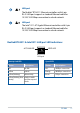
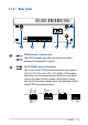
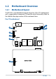
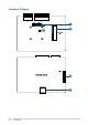
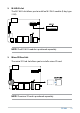
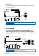
Table Of Contents
- About this manual
- Chapter 1: Getting to know your Embedded Computer
- Chapter 2: Using your Embedded Computer
- Chapter 3: Upgrading your Embedded Computer
- 3.1 Removing the bottom cover
- 3.2 Replacing the bottom cover
- 3.3 Removing the top cover
- 3.4 Replacing the top cover
- 3.5 Installing a nano SIM card (Front panel)
- 3.6 Installing an SD card (Top side)
- 3.7 Installing a wireless card to the M.2 slot (Top side)
- 3.8 Installing an mPCIe / mSATA module (Bottom side)
- 3.9 Installing antennas (optional)
- 3.10 Installing the wall mount
- 3.11 Installing DIN rail clips (optional)
- 3.12 Installing the terminal block (optional)
- Chapter 4: Setting up your Embedded Computer
- Appendix

14
PE100A
Isolated DIO connector
The Isolated Digital Input/Output (DIO) connector
provides electrical isolation (up to 2500 VDC) of digital
input and output signals, which allow micro controllers
to detect and output logic states. The high voltage
protection can be used in industrial level uses. Please refer
to the illustration below for the Isolated DIO connector’s
pin definitions.
DO4 L
DO4 H
DO3 L
DO3 H
DO2 L
DO2 H
DO1 L
DO1 H
DI4 L
DI4 H
DI3 L
DI3 H
DI2 L
DI2 H
DI1 L
DI1 H
Power input
The supplied terminal block power adapter converts AC
power to DC power for use with this jack. Power supplied
through this jack supplies power to the Embedded
Computer.
WARNING! The power adapter may become warm to
hot when in use. Do not cover the adapter and keep
it away from your body.
Functional Earth Ground
The Functional Earth Ground provides you with a
grounding point.
Signal Specifications
DO
Output voltage range 0~24 VDC
Rated output current 1A
DI
Voltage for logic “0” 0~3 VDC
Voltage for logic “1” 5~24 VDC
Rated input current ±50 mA