PE1100N Series Embedded Computer User Manual
E22181 First Edition September 2023 COPYRIGHT INFORMATION No part of this manual, including the products and software described in it, may be reproduced, transmitted, transcribed, stored in a retrieval system, or translated into any language in any form or by any means, except documentation kept by the purchaser for backup purposes, without the express written permission of ASUSTeK COMPUTER INC. (“ASUS”).
Contents About this manual..............................................................................................................5 Conventions used in this manual.......................................................................................... 6 Package contents...............................................................................................................7 Chapter 1: Getting to know your Embedded Computer 1.1 Features.......................................................
Chapter 4: Setting up your Embedded Computer 4.1 Requirements............................................................................................................56 4.2 Installing or Updating the OS..............................................................................56 Appendix Safety information..............................................................................................................60 Setting up your system.............................................................
About this manual This manual provides information about the hardware and software features of your Embedded Computer, organized through the following chapters: Chapter 1: Getting to know your Embedded Computer This chapter details the hardware components of your Embedded Computer. Chapter 2: Using your Embedded Computer This chapter provides you with information on using your Embedded Computer.
Conventions used in this manual To highlight key information in this manual, some text are presented as follows: IMPORTANT! This message contains vital information that must be followed to complete a task. NOTE: This message contains additional information and tips that can help complete tasks. WARNING! This message contains important information that must be followed to keep you safe while performing certain tasks and prevent damage to your Embedded Computer's data and components.
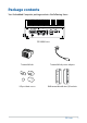
Package contents Your Embedded Computer package contains the following items: PE1100N Series Terminal blocks Terminal block power adapter I/O port dust covers Wall mount kit with two (2) brackets PE Series 7
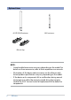
Optional items 4G LTE/5G NR antennas Wi-Fi antennas DIN rail clips NOTE: • Some bundled accessories may vary depending on the model. For details on these accessories, refer to their respective user manuals. • Illustrations of the device and accessories are for reference only. Actual product specifications may vary depending on the model.
Getting to know your Embedded Computer 1
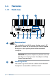
1.1 Features 1.1.1 Front view Power input jack The supplied terminal block power adapter converts AC power to DC power for use with this jack. Power supplied through this jack supplies power to the Embedded Computer. WARNING! The power adapter may become warm to hot when in use. Do not cover the adapter and keep it away from your body. Cellular Signal LED The cellular signal LED indicates whether the Embedded Computer is connected to a cellular network.
Wi-Fi Signal LED The Wi-Fi signal LED indicates whether the Embedded Computer is connected to a wireless network. Serial (COM/CAN) Signal LED Each numbered LED indicates whether a device that is connected to the corresponding serial (COM/CAN) port on the back panel is communicating through the serial bus. Power button The power button allows you to turn the Embedded Computer on or off.
LAN port The 8-pin RJ-45 LAN port supports a standard Ethernet cable for 10/100/1000 Mbps connection to a local network. Functional Earth Ground The Functional Earth Ground provides you with a grounding point.
1.1.
Isolated DIO connector The Isolated Digital Input/Output (DIO) connector provides electrical isolation (up to 2500 VDC) of digital input and output signals, which allow micro controllers to detect and output logic states. The high voltage protection can be used in industrial level uses. Please refer to the illustration below for the Isolated DIO connector’s pin definitions.
Serial (COM) connector The 9-pin DB9 connector allows you to connect RS-232/ RS-422/RS-485 devices that have serial ports, such as bar code scanner, modem, or printers. Please refer to the table below for the pin definitions of the different COM connectors. NOTE: Default set to RS-232.
Serial (CAN) connector (on selected models) The 9-pin CAN Bus serial connector allows you to connect devices with a CAN interface, such as an electronic control unit (ECU). Please refer to the table below for the pin definitions of the CAN Bus connector.
WWAN-MIMO wireless antenna jack The WWAN-MIMO antenna jack allows you to connect a wireless antenna to enhance 5G NR MIMO signals. NOTE: The 4G LTE/5G NR wireless antennas are optional and may not come bundled. WLAN Wireless antenna jack The Wi-Fi wireless antenna jack allows you to connect a wireless antenna for Wi-Fi signals. NOTE: The Wi-Fi wireless antennas are optional and may not come bundled.
1.1.3 Left view NOTE: The features on this side are covered with a metal cover. Ensure to remove and replace the metal cover when accessing these features. For more information on removing and replacing the metal cover, refer to Installing a nano SIM card. Debug console port (on selected models) This micro USB port allows you to connect a computer to the integrated USB to UART debug console (baud rate 115200) using a micro USB cable.
Nano SIM card slot This slot allows you to insert a Nano SIM card. Force recovery pinhole The hard reset pinhole allows you to put your Embedded Computer into Force Recovery Mode to update or flash the OS. WWAN wireless antenna jack The WWAN antenna jack allows you to connect a wireless antenna to enhance 4G LTE/5G NR signals. NOTE: The 4G LTE/5G NR wireless antennas are optional and may not come bundled.
1.1.4 Right view Expansion slot This slot allows you to install an ASUS Expansion Module (AEM) for additional I/O ports. NOTE: Contact your ASUS sales representative for more information on AEMs.
1.2 Motherboard overview 1.2.1 Motherboard layout The PE1100N Series is an Embedded Computer based on a 3.5” motherboard. Refer to the table for the page numbers of the numbered items. 3.
Layout contents Page 3.5” motherboard 1. USB 2.0 connector 23 2. M.2 (M-key) slot 23 3. M.2 (E-key) slot 24 4. M.2 (B-key) slot 24 5. RTC Battery connector 25 6.
1.2.2 1. Internal connectors USB 2.0 connector The USB 2.0 connector allows you to connect a USB module for additional USB 2.0 ports. The USB 2.0 connector provides data transfer speeds of up to 480 MB/s connection speed. 2. M.2 (M-key) slot The M.2 slot allows you to install an M-key (PCIe, I2C and SMBus) type 2242/2260/2280 M.2 device, such as an M.2 SSD module. NOTE: The M.2 SSD module is purchased separately.
3. M.2 (E-key) slot The M.2 (E-key) slot allows you to install an E-key (PCIe, USB 2.0, I2C, and PCM), type 2230 M.2 Wi-Fi module. NOTE: The M.2 Wi-Fi module is purchased separately. 4. M.2 (B-key) slot The M.2 (B-key) slot allows you to install a B-key (PCIe, USB2.0/3.0) type 3042/3052 M.2 device, such as a 4G LTE, 5G NR, or AEM module. NOTE: The M.2 4G LTE, 5G NR, or AEM module is purchased separately.
5. RTC Battery connector The RTC Battery connector allows you to connect a lithium CMOS battery. 6. SO-DIMM slot The SO-DIMM slot can support the following SOMs: • • NVIDIA® Jetson Orin Nano™ NVIDIA® Jetson Orin™ NX NOTE: Your Embedded Computer comes pre-installed with a Systemon-Module (SOM). The actual SOM installed may vary, depending on your specifications.
PE Series
Using your Embedded Computer 2
2.1 Getting started 2.1.1 Connect the AC power adapter to your Embedded Computer To connect the AC power adapter to your Embedded Computer: A. Connect the power cord to the AC power adapter. B. Connect the AC power adapter to the terminal block power adapter. C. Connect the 3-pin terminal block DC power connector into your Embedded Computer’s power (DC) input. D. Plug the AC power adapter into a 100 V~240 V power source.
IMPORTANT! • We strongly recommend that you use only UL-certified power adapters and cables that meet the following requirements or ones that you purchased as an option with your Embedded Computer. 65 W Power adapter Input voltage: 100-240 Vac Input frequency: 50-60 Hz Rated output current: 5.41 A-2.7 A (65.0 W) Rated output voltage: 12-24 Vdc System Rated voltage: 12-24 Vdc Rated current: 5.41 A-2.7 A (65.0 W) • We strongly recommend that you use a grounded wall socket while using your Embedded Computer.
2.1.2 Connect a display panel to your Embedded Computer You can connect a display panel or projector to your Embedded Computer that has the following connector(s): • HDMI™ connector To connect a display panel to your Embedded Computer: Connect one end of an HDMI™ cable to an external display, and the other end of the cable to your Embedded Computer’s HDMI™ port.
2.1.3 Connect the USB cable from keyboard or mouse You can connect generally any USB keyboard and mouse to your Embedded Computer. You can also connect a USB dongle for a wireless keyboard and mouse set. To connect a keyboard and mouse to your Embedded Computer: Connect the USB cable from your keyboard and mouse to any of the USB ports of your Embedded Computer. NOTE: • The keyboard varies with country and/or region. • The keyboard and mouse are purchased separately.
2.1.4 Turn on your Embedded Computer Press the power button to turn on your Embedded Computer if it does not power on automatically when you connect it to a power source.
2.2 Turning off your Embedded Computer If your Embedded Computer is unresponsive, press and hold the power button for at least four (4) seconds until your Embedded Computer turns off.
PE Series
3 Upgrading your Embedded Computer
3.1 Removing the bottom cover IMPORTANT! • Ensure that your hands are dry before proceeding with the rest of the installation process. Before installing any of the features in this guide, use a grounded wrist strap or touch a safely grounded object or metal object to avoid damaging them due to static electricity. • Turn off the power of your Embedded Computer and allow it to cool for at least 10 minutes before performing any installation/ uninstallation process.
3.2 Replacing the bottom cover Align the screw holes on the bottom cover with those on your Embedded Computer’s chassis. Secure the bottom cover using the screws removed previously.
3.3 Installing a nano SIM card (optional) Your Embedded Computer comes with two (2) nano SIM card slots. NOTE: Nano SIM cards are purchased separately. 1. Remove the two (2) screws securing the metal slot cover, and then remove the cover. 2. Insert your nano SIM card(s) into the nano SIM card slot(s) with the gold contacts facing up. Make sure that each card is pushed all the way into its card slot.
3. Replace the metal slot cover, and secure it with the screws removed previously.
3.4 Installing an M.2 (E-key) module Your Embedded Computer comes with an M.2 (E-key) slot that allow you to install an M.2 wireless (Wi-Fi / Bluetooth) module. To install an wireless module: 1. Remove the screw from the M.2 standoff. 2. Align and insert the wireless card into its slot inside the Embedded Computer. 3. Gently push down the wireless card on top of the standoff, and then fasten it using the previously removed screw. 4.
ANT.2 ANT.3 ANT.2 ANT.3 Ant. Jack Module Connector ANT. 2 WLAN-MAIN ANT.
3.5 Installing an M.2 (M-key) module Your Embedded Computer comes with an M.2 (M-key) slot that allows you to install an M.2 SSD (M-key, supports 2242/2260/2280 PCIe x4) module. To install an M.2 SSD module: 1. Remove the screw from the standoff. 2. If the standoff is already seated in the right mounting hole to fit your M.2 SSD module, skip to step 4. 3. Unscrew the standoff (A) and install it to a mounting hole that matches the length of your M.2 SSD module (B). 4. Align and insert the M.
5. Gently push down the M.2 SSD on top of the standoff and fasten it using a screw.
3.6 Installing an M.2 (B-key) module Your Embedded Computer comes with an M.2 (B-key) slot that allows you to install a B-key (PCIe, USB2.0/3.0) type 3042/3052 M.2 device, such as a 4G LTE, 5G NR, or AEM module. To install a 5G NR module: 1. Remove the screw from the M.2 standoff. 2. If the standoff is already seated in the right mounting hole to fit your 5G NR module, skip to step 4. 3. Unscrew the standoff (A) and install it to a mounting hole that matches the length of your module (B). 4.
5. Gently push down the module on top of the standoff, and then fasten it using the previously removed screw. 6. (Optional) Connect the RF cables from the antennas to your module. Make sure that the correct cable is attached to each of the connectors by referring to the illustration below. WARNING! RF modules are intended for OEM or host integrators only. For availability of system level RF certification, check with your OEM integrator.
To install a 4G LTE module: 1. Remove the screw from the M.2 standoff. 2. If the standoff is already seated in the right mounting hole to fit your 4G LTE module, skip to step 4. 3. Unscrew the standoff (A) and install it to a mounting hole that matches the length of your module (B). 4. Align and insert the module into its slot inside the Embedded Computer. 5. Gently push down the module on top of the standoff, and then fasten it using the previously removed screw.
6. (Optional) Connect the RF cables from the antennas to your module. Make sure that the correct cable is attached to each of the connectors by referring to the illustration below. WARNING! RF modules are intended for OEM or host integrators only. For availability of system level RF certification, check with your OEM integrator. NOTE: • Please refer to the Installing antennas section for more information on installing the antennas.
3.7 Installing antennas (optional) You may install antennas to the six (6) antenna jacks located on the rear panel. The installed antennas can be connected to a 4G LTE or 5G NR module installed in the M.2 B-key slot or to a wireless card installed in the M.2 Wi-Fi slot. NOTE: • It is recommended that you install the antennas as shown in the diagram below. • 4G LTE/5G NR antennas are flatter and slightly longer than the Wi-Fi antennas.
To install an antenna: NOTE: If your Embedded Computer came pre-installed with antenna jacks, skip to step 8. 1. Remove the bottom cover. Refer to Removing the bottom cover for details. 2. Prepare the RF connector and cable. 3. Remove the rubber caps from the antenna holes. 4. Insert the antenna jack end of the RF connector and cable into the antenna jack from within the chassis outwards.
5. Insert the bundled O-ring to the antenna jack (A), then secure the antenna jack using the bundled hex screw (B). 6. Connect the other end of the RF connector and cable to your wireless card (refer to Installing an M.2 (E-key) module for details) or to your 4G LTE or 5G NR module (refer to Installing an M.2 (B-key) module for details). 7. Replace the bottom cover. Refer to Replacing the bottom cover for details. 8.
3.8 Installing wall mount brackets (optional) 1. Remove the four (4) rubber feet screws (A), and then remove the rubber feet from them (B). 2. Align the wall mount brackets to the rubber feet screw holes, and then secure the wall mount brackets to your Embedded Computer using the rubber feet screws.
NOTE: • The wall mount brackets are compatible with most DIN rail clips available on the market. • The rubber feet screws and wall mount bracket screws are the same screws. 3.9 Mounting to a surface (optional) You can install your Embedded Computer to a suitable surface using wall mount brackets. 1. Make sure that the wall mount brackets are already installed. Refer to the section Installing wall mount brackets for installation instructions. 2.
3.10 Installing DIN rail clips (optional) 1. Make sure that the wall mount brackets are already installed. Refer to the section Installing wall mount brackets for installation instructions. 2. Align the screw holes on the DIN rail clips to the ones on the wall mount brackets as shown below. 3. Secure the DIN rail clips to the wall mount using the screws bundled with the DIN rail clips. 4.
3.11 Installing the terminal block (optional) You may install terminal blocks into the Isolated DIO connector, which allow you to support additional devices with serial ports or micro controllers by referring to the pin definitions and connecting cables to the slots on the terminal blocks as needed. IMPORTANT! Connect only one (1) cable to a slot on the terminal block. NOTE: • The terminal block is purchased separately.
4 Setting up your Embedded Computer
4.1 Requirements Before you start setting up your Embedded Computer, make sure you have the following available: • 1 x micro USB cable with data transfer function (to connect a host PC running on Linux OS to your Embedded Computer’s flash port) • 1 x Power supply • 1 x Monitor with HDMI™ cable • 1 x Keyboard and Mouse set NOTE: Make sure to use the bundled power supply, or, if you are using another power supply, ensure to use a 12~24V power supply. 4.
4. Insert the tip of an unfolded paper clip into the force recovery pinhole (refer to the Left view section for the location), press in, and hold. 5. While holding the paper clip in place, connect the power adapter, which should automatically power on your Embedded Computer. If it does not, press the power button. 6. Wait three (3) seconds, and then release the paper clip from the force recovery pinhole. You should now be in force recovery mode and ready to flash the OS image. 7.
PE Series
Appendix
Safety information Your Embedded Computer is designed and tested to meet the latest standards of safety for information technology equipment. However, to ensure your safety, it is important that you read the following safety instructions. Setting up your system • • • • • • • • • 60 Read and follow all instructions in the documentation before you operate your system. Do not use this product near water or a heated source. Set up the system on a stable surface.
Care during use • Do not walk on the power cord or allow anything to rest on it. • • Do not spill water or any other liquids on your system. When the system is turned off, a small amount of electrical current still flows. Always unplug the power cord from the power outlets before cleaning the system. Exercise caution when operating this product at full load, as the product may reach elevated temperatures, especially the outer casing.
Lithium-Ion Battery Warning CAUTION! Danger of explosion if battery is incorrectly replaced. Replace only with the same or equivalent type recommended by the manufacturer. Dispose of used batteries according to the manufacturer’s instructions. NO DISASSEMBLY The warranty does not apply to the products that have been disassembled by users DO NOT throw the Embedded Computer in municipal waste. This product has been designed to enable proper reuse of parts and recycling.
Regulatory notices FCC Compliance Information Responsible Party: Asus Computer International Address: Phone / Fax No: 48720 Kato Rd., Fremont, CA 94538, USA (510)739-3777 / (510)608-4555 This device complies with Part 15 of the FCC Rules. Operation is subject to the following two conditions: (1) This device may not cause harmful interference, and (2) This device must accept any interference received including interference that may cause undesired operation.
FCC RF Exposure Information This device meets the government’s requirements for exposure to radio waves. This device is designed and manufactured not to exceed the emission limits for exposure to radio frequency (RF) energy set by the Federal Communications Commission of the U.S. Government. The exposure standard employs a unit of measurement known as the Specific Absorption Rate, or SAR. The SAR limit set by the FCC is 1.6 W/kg.
Compliance Statement of Innovation, Science and Economic Development Canada (ISED) This device complies with Innovation, Science and Economic Development Canada licence exempt RSS standard(s). Operation is subject to the following two conditions: (1) this device may not cause interference, and (2) this device must accept any interference, including interference that may cause undesired operation of the device.
VCCI: Japan Compliance Statement Class A ITE Japan RF Equipment Statement 屋外での使用について 本製品は、5GHz帯域での通信に対応しています。電波法の定めにより 5.2GHz、5.
Declaration of compliance for product environmental regulation ASUS follows the green design concept to design and manufacture our products, and makes sure that each stage of the product life cycle of ASUS product is in line with global environmental regulations. In addition, ASUS disclose the relevant information based on regulation requirements. Please refer to https://csr.asus.com/Compliance.
Türkiye RoHS AEEE Yönetmeliğine Uygundur ASUS Recycling/Takeback Services ASUS recycling and takeback programs come from our commitment to the highest standards for protecting our environment. We believe in providing solutions for you to be able to responsibly recycle our products, batteries, other components as well as the packaging materials. Please go to https:// csr.asus.com/english/Takeback.htm for detailed recycling information in different regions.
甲類警語 警告使用者:此為甲類資訊技術設備,於居住環境中使用時,可能會造 成射頻擾動,在此種情況下,使用者會被要求採取某些適當的對策。 Taiwan BSMI Class A Notice This product is Class A. In a domestic environment, this product may cause radio interference. You may be required to take adequate measures.
UK: The Radio Equipment Regulations 2017 (S.I. 2017/1206) Simplified UKCA Declaration of Conformity ASUSTek Computer Inc. hereby declares that this device is in compliance with the essential requirements and other relevant provisions of The Radio Equipment Regulations 2017 (S.I. 2017/1206). Full text of UKCA declaration of conformity is available at https://www.asus.com/support/.
EU: Radio Equipment Directive (Directive 2014/53/EU) Simplified EU Declaration of Conformity ASUSTek Computer Inc. hereby declares that this device is in compliance with the essential requirements and other relevant provisions of Directive 2014/53/EU. Full text of EU declaration of conformity is available at https://www.asus.
Zjednodušené prohlášení o shodě EU Společnost ASUSTek Computer Inc. tímto prohlašuje, že toto zařízení splňuje základní požadavky a další příslušná ustanovení směrnice 2014/53/ EU. Plné znění prohlášení o shodě EU je k dispozici na adrese https://www.asus.com/support/ V zemích uvedených v tabulce je provoz sítě Wi-Fi ve frekvenčním rozsahu 5 150 - 5 350 MHz povolen pouze ve vnitřních prostorech: Forenklet EU-overensstemmelseserklæring ASUSTeK Computer Inc.
Vienkāršota ES atbilstības paziņojums ASUSTeK Computer Inc. ar šo paziņo, ka šī ierīce atbilst Direktīvas 2014/53/ES būtiskajām prasībām un citiem citiem saistošajiem nosacījumiem. Pilns ES atbilstības paziņojuma teksts pieejams šeit: https://www.asus.com/support/ Wi-Fi darbība 5150–5350 MHz ir jāierobežo lietošanai telpās valstīs, kuras norādītas tālāk. Supaprastinta ES atitikties deklaracija Šiame dokumente bendrovė „ASUSTek Computer Inc.
Förenklad EU-försäkran om överensstämmelse ASUSTek Computer Inc. deklarerar härmed att denna enhet överensstämmer med de grundläggande kraven och andra relevanta bestämmelser i direktiv 2014/53/EU. Fullständig text av EU-försäkran om överensstämmelse finns på https://www.asus.com/support/ WiFi som använder 5150-5350 MHz kommer att begränsas för användning inomhus i de länder som anges i tabellen: ประกาศเกี่ยวกับความสอดคล้องของสหภาพยุโรปแบบย่อ ASUSTek Computer Inc.
Service and Support Visit our multi-language website at https://www.asus.com/support/.