PE200U Series Embedded Computer User Manual
E18007 Revised Edition V4 May 2022 COPYRIGHT INFORMATION No part of this manual, including the products and software described in it, may be reproduced, transmitted, transcribed, stored in a retrieval system, or translated into any language in any form or by any means, except documentation kept by the purchaser for backup purposes, without the express written permission of ASUSTeK COMPUTER INC. (“ASUS”).
Contents About this manual..................................................................................................................6 Package contents...................................................................................................................8 Chapter 1: Getting to know your Embedded Computer 1.1 Features...........................................................................................................................12 1.1.1 Front view..............................
Chapter 3: 3.1 3.2 3.3 3.4 3.5 3.6 3.7 3.8 3.9 3.10 3.11 3.12 3.13 3.14 3.15 3.16 Upgrading your Embedded Computer Removing the bottom cover....................................................................................46 Replacing the bottom cover....................................................................................47 Installing memory modules.....................................................................................47 Installing 2.5” storage device...........................
Appendix Safety information..................................................................................................................88 Setting up your system..................................................................................................................88 Care during use.................................................................................................................................89 Regulatory notices...............................................................
About this manual This manual provides information about the hardware and software features of your Embedded Computer, organized through the following chapters: Chapter 1: Getting to know your Embedded Computer This chapter details the hardware components of your Embedded Computer. Chapter 2: Using your Embedded Computer This chapter provides you with information on using your Embedded Computer.
Conventions used in this manual To highlight key information in this manual, some text are presented as follows: IMPORTANT! This message contains vital information that must be followed to complete a task. NOTE: This message contains additional information and tips that can help complete tasks. WARNING! This message contains important information that must be followed to keep you safe while performing certain tasks and prevent damage to your Embedded Computer's data and components.
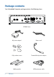
Package contents Your Embedded Computer package contains the following items: PE200U Series 8 AC power adapter* Power cord* I/O port dust covers Terminal block power adapter Wall mount kit SATA and power cable PE Series
Optional item(s) DIN rail clips NOTE: • *The bundled power adapter may vary by model and territories. • Some bundled accessories may vary with different models. For details on these accessories, refer to their respective user manuals. • The device illustration is for reference only. Actual product specifications may vary with models.
Getting to know your Embedded Computer 1
1.1 Features 1.1.1 Front view LAN port with PoE (on selected models) The 8-pin RJ-45 LAN port supports a standard Ethernet cable for connection to a local network, and supports Power over Ethernet (PoE). Power button The power button allows you to turn the Embedded Computer on or off. You can use the power button to put your Embedded Computer to sleep mode or press it for four (4) seconds to force shutdown your Embedded Computer.
HDMITM port The HDMI (High Definition Multimedia Interface) port supports a Full-HD device such as an LCD TV or monitor to allow viewing on a larger external display. Dual-mode DisplayPort This port allows you to connect your Embedded Computer to an external display, and supports DVI or HDMITM adapters. Antenna hole The antenna hole allows you to connect a wireless antenna to enhance wireless signal reception.
1.1.2 Rear view Serial (COM) connector (on selected models) The 9-pin RS-232 serial (COM) connector allows you to connect devices that have serial ports such as bar code scanner, modem, or printers. USB 2.0 port (on selected models) The USB (Universal Serial Bus) port is compatible with USB 2.0 or USB 1.1 devices such as keyboards, pointing devices, flash disk drives, external HDDs, speakers, cameras and printers.
Antenna hole The antenna hole allows you to connect a wireless antenna to enhance wireless signal reception. Headphone jack This port allows you to connect amplified speakers or headphones. Functional Earth Ground (on selected models) The Functional Earth Ground provides you with a grounding point.
1.2 Motherboard Overview 1.2.1 Motherboard layout The PE200U Series features a motherboard with a 3.5” dimension (146mm x 105mm).
Layout contents Page 1. M.2 Wi-Fi slot 23 2. Nano SIM Card slot 23 3. Mini PCIe/mSATA slot 21 4. DIMM slot 16 5. Low Pin Count connector 25 6. Battery connector 25 7.. GPIO connector 26 8. Mini PCIe/mSATA configuration jumper 19 9. Clear RTC RAM jumper 17 10. System Management Bus connector 26 11. I2C connector 27 12. Serial Port connector 28 13. Micro SD card slot 22 14. M.2 slot 22 15. USB 2.0 connector 29 16. SATA 6Gb/s & SATA Power connector 20 17.
1.2.2 System memory The motherboard comes with a Small Outline Dual Inline Memory Module (SODIMM) slot designed for DDR4 (Double Data Rate 4) memory modules.
1.2.3 1. Onboard jumpers Clear RTC RAM jumper The Clear RTC RAM jumper allows you to clear the Real Time Clock (RTC) RAM in the CMOS, which contains the date, time, system passwords, and system setup parameters. To erase the RTC RAM: 1. Turn OFF the computer and unplug the power cord. 2. Short-circuit pin 1-2 with a metal object or jumper cap for about 5-10 seconds. 3. Plug the power cord and turn ON the computer. 4.
2. HW WDT Enable jumper A watchdog timer is an electronic timer that is used to detect and recover from computer malfunctions. The HW WDT (watchdog timer) Enable jumper allows the HW watchdog resets the system automatically even when the system crashes. NOTE: The default setting for this jumper is set to HW WDT enabled with a jumper cap attached.
3. AT/ATX Mode Configuration jumper The AT/ATX Mode Configuration jumper allows you to switch between AT or ATX modes. The default setting for this jumper is set to ATX mode with a jumper cap attached, to switch to AT mode, remove the jumper cap. 4. Mini PCIe/mSATA configuration jumper The Mini PCIe/mSATA configuration jumper allows you to select between Mini PCIe mode or mSATA mode. Set to pins 1-2 for mSATA mode, or set to pins 2-3 for Mini PCIe mode.
1.2.4 1. Internal connectors SATA 6Gb/s & SATA Power connector The SATA 6Gb/s and SATA Power connectors allow you to connect SATA devices such as optical disc drives and hard disk drives via a SATA cable and power cable. Connector type Wafer HD 4P, 2.0mm pitch NOTE: Ensure to use the bundled cable when connecting a storage device to this connector.
2. Mini PCIe/mSATA slot The Mini PCIe/mSATA slot allows you to install a Mini PCIe or mSATA peripheral device. NOTE: • The Mini PCIe / mSATA peripheral device is purchased separately. • The mSATA shares the same slot with a full-length Mini PCIe.
3. Micro SD Card slot The Micro SD Card slot allows you to install a Micro SD card. NOTE: The Micro SD card is purchased separately. 4. M.2 slot The M.2 slot allows you to install 2242 M.2 devices such as 2242 M.2 SSD modules. NOTE: • The M.2 SSD module is purchased separately. • This motherboard supports 2242 PCIE SSD devices only.
5. M.2 Wi-Fi slot The M.2 Wi-Fi slot allows you to install an M.2 Wi-Fi module (E-key, type 2230). NOTE: The M.2 Wi-Fi module is purchased separately. 6. Nano SIM Card slot The Nano SIM Card slot allows you to install a Nano SIM card. NOTE: The Nano SIM card is purchased separately.
7. Power button connector The Power Button connector allows you to connect an external power button. 8. Chassis Intrusion connector The Chassis Intrusion connector allows you to connect a intrusion sensor or microswitch for the chassis intrusion detection feature. When you remove any chassis component, the sensor or microswitch triggers and sends a high level signal and records a chassis intrusion event.
9. Battery connector The Battery connector allows you to connect the lithium CMOS battery. 10. Low Pin Count connector The Low Pin Count connector allows you to connect a low pin count (LPC) debug card that offers a faster, more efficient motherboard troubleshooting solution. When connected to a debug card, users can view error and debugging codes on the card and get a better idea of initialization and recovery processes. Connector type BOX header 2x5p, K10, 2.
11. System Management Bus connector The System Management Bus (SMBus) connector allows you to connect SMBus devices. This connector is generally used for communication with the system and power management-related tasks. Connector type Header 1x4p, 2.0mm pitch 12. GPIO connector The GPIO connector allows you to connect a general purpose input/ output module which allows you to customize the digital signal input/ output. Connector type 28 PE Series BOX header 2x5p, K9, 2.
13. I2C connector The I2C (Inter-Integrated Circuit) connector allows you to connect an I2C compatible IoT security module. Connector type Header 2x3p, K6, 2.0mm pitch 14. SPI TPM connector The SPI TPM connector supports a Trusted Platform Module (TPM) system, which can securely store keys, digital certificates, passwords, and data. A TPM system also helps enhance network security, protects digital identities, and ensures platform integrity. Connector type Header 2x7p,K14, 2.
15. Serial Port connector The Serial (COM) Port connector allows you to connect a serial port module. Connect the serial port module cable to this connector, then install the module to a slot opening on the system chassis. Connector type BOX header 2x5p, K10, 2.0mm pitch NOTE: • The serial port module is purchased separately. • COM1 and COM2 support RS-232/422/485. • COM 3, COM4, COM5, and COM6 support RS-232.
16. USB 2.0 connector The USB 2.0 connector allows you to connect a USB module for additional USB 2.0 ports. The USB 2.0 connector provides data transfer speeds of up to 480 MB/s connection speed. Connector type BOX header 2x5p, K9, 2.0mm pitch WARNING! DO NOT connect a 1394 cable to the USB connectors. Doing so will damage the motherboard! NOTE: The USB 2.0 module is purchased separately.
17. DC-in 4-Pin Power connector The DC-in 4-pin Power connector is for DC power input. Using a compatible power cable and power board, you may connect a suitable power supply with DC-in jacks.
18. System Panel connector The System Panel connector supports several chassis-mounted functions. Connector type BOX header 2x5p 2.0mm pitch • System Power LED connector (PLED) The 2-pin connector allow you to connect the System Power LED. The System Power LED lights up when the system is connected to a power source, or when you turn on the system power, and blinks when the system is in sleep mode.
19. Line Out / Mic connector The Line Out / Mic connector is for a line out /microphone module that supports HD Audio. Connect one end of the line Out / mic module cable to this connector. Connector type BOX header 2x5p, K8, 2.0mm pitch NOTE: We recommend that you connect a high-definition line out / mic module to this connector to avail of the motherboard’s highdefinition audio capability.
Using your Embedded Computer 2
2.1 Getting started 2.1.1 Connect the AC power adapter to your Embedded Computer To connect the AC power adapter to your Embedded Computer: A. Connect the power cord to the AC power adapter. B. Connect the DC power connector into your Embedded Computer’s power (DC) input. C. Plug the AC power adapter into a 100 V~240 V power source.
NOTE: The power adapter may vary in appearance, depending on the model and your region. Refer to the following for more information on the different power adapters, as well as the system: 65W Power adapter • Input voltage: 100-240 Vac • Input frequency: 50-60 Hz • Rated output current: 5.417 A / 3.42 A / 5.41 A-2.7 A (65.0 W) • Rated output voltage: 12.0 V / 19.0 V / 12-24 Vdc 120W Power adapter • Input voltage: 100-240 Vac • Input frequency: 50-60 Hz • Rated output current: 10.0 A / 6.
IMPORTANT! • We strongly recommend that you use only the AC power adapter and cable that came with your Embedded Computer. • We strongly recommend that you use a grounded wall socket while using your Embedded Computer. • The socket outlet must be easily accessible and near your Embedded Computer. • To disconnect your Embedded Computer from its main power supply, unplug your Embedded Computer from the power socket.
2.1.2 Connect a display panel to your Embedded Computer You can connect a display panel or projector to your Embedded Computer that has the following connectors: • HDMITM connector • DisplayPort To connect a display panel to your Embedded Computer: Connect one end of an HDMITM, or a DisplayPort cable to an external display, and the other end of the cable to your Embedded Computer’s HDMITM port, or DisplayPort.
Connect display via DisplayPort 40 PE Series
2.1.3 Connect the USB cable from keyboard or mouse You can connect generally any USB keyboard and mouse to your Embedded Computer. You can also connect a USB dongle for a wireless keyboard and mouse set. To connect a keyboard and mouse to your Embedded Computer: Connect the USB cable from your keyboard and mouse to any of the USB ports of your Embedded Computer. NOTE: • The keyboard varies with country or region. • The keyboard and mouse are purchased separately.
2.1.4 Turn on your Embedded Computer Press the power button to turn on your Embedded Computer.
2.2 Turning your Embedded Computer off If your Embedded Computer is unresponsive, press and hold the power button for at least four (4) seconds until your Embedded Computer turns off. 2.3 Putting your Embedded Computer to sleep To put your Embedded Computer on Sleep mode, press the Power button once. 2.4 Entering the BIOS Setup BIOS (Basic Input and Output System) stores system hardware settings that are needed for system startup in the Embedded Computer.
2.4.1 Load default BIOS settings To load the default values for each of the parameters in your BIOS: 1. Enter the BIOS by pressing or on the POST screen. NOTE: POST (Power-On Self Test) is a series of software controlled diagnostic tests that run when you turn on your Embedded Computer. 2. Navigate to the Exit menu. 3. Select the Load Optimized Defaults option, or you may press . 4. Select OK to load the default BIOS values.
3 Upgrading your Embedded Computer
IMPORTANT! • Ensure that your hands are dry before proceeding with the rest of the installation process. Before installing any of the features in this guide, use a grounded wrist strap or touch a safely grounded object or metal object to avoid damaging them due to static electricity. • Turn off the power of your Embedded Computer, and allow it to cool for at least 10 minutes before performing any installation/ uninstallation process. NOTE: The illustrations in this section are for reference only.
3.2 Replacing the bottom cover 1. Align the bottom cover with the screw holes, then replace the bottom cover onto the Embedded Computer. 2. Secure the bottom cover using the four (4) screws removed previously. 3. Replace the four (4) rubber feet screws removed previously. 3.3 Installing memory modules Your Embedded Computer comes with a SO-DIMM memory slot that allow you to install a DDR4 SO-DIMM.
3.4 Installing 2.5” storage device 1. Prepare your 2.5” storage device, then align it with the storage bay on the bottom cover of your Embedded Computer. 2. Connect the storage device cable to the storage device. 3. Insert your storage device into the storage bay. 4. Secure the storage device to the storage bay using four (4) screws. IMPORTANT! This device only supports 7mm 2.5” HDD or SSD.
5. Connect the storage device cable to the SATA6G and SATA_PWR connectors on the motherboard. 6. Replace the bottom cover, then secure the bottom cover using the four (4) screws removed previously. 7. Replace the four (4) rubber feet screws removed previously.
3.5 Installing an M.2 SSD 1. (optional) Replace the stand screw if it has been removed. 2. Align and insert the M.2 SSD into its slot inside the Embedded Computer, then gently push down the M.2 SSD on top of the stand screw hole and fasten it using a screw.
3.6 Installing a nano SIM card 1. (optional) Remove the mPCIe or mSATA card if there is a mPCIe or mSATA card installed by removing the two (2) screws securing the mPCIe or mSATA card first, then removing the mPCIe or mSATA card. 2. Push the nano SIM cover towards the front of your Embedded Computer. 3. Lift the nano SIM cover. 4. Place the nano SIM into the nano SIM slot. 5. Replace the nano SIM cover. 6.
3.7 Installing an SD card 1. Remove the five (5) screws on the rear cover, then slightly pull the rear cover outwards, but do not remove it completely. 2. Insert your SD card into the SD card slot. Ensure that the SD card is pushed all the way into the SD card slot.
3. Once your SD card is properly installed into the SD card slot, replace the rear cover and secure it using the five (5) screws removed previously.
3.8 Installing a wireless card to the M.2 slot 1. Remove the M.2 stand screw. 2. Align and insert the wireless card into the M.2 slot inside the Embedded Computer. 3. Gently push down the wireless card on top of the screw hole, and then fasten it using the previously removed stand screw. 4. (optional) Connect the RF cables from the antennas to your wireless card. Ensure that the correct cable is attached to each of the connectors by referring to the illustration on the next page.
WIFI-Main WIFI-Aux (DIV) WIFI-Aux (DIV) WIFI-Main PE Series 55
3.9 Installing an mPCIe / mSATA module Your Embedded Computer comes with an mPCIe / mSATA slot that allows you to install an LTE mPCIe module, mPCIe Coral TPU module, or mSATA storage module. To install an LTE mPCIe module: 1. Remove the two (2) standoff screws 2. Align and insert the LTE module into the slot. 3. Press down, and then secure it in place using the two (2) screws previously removed. 4. (optional) Connect the RF cables from the antennas to your LTE module.
PE Series 57
3.10 Installing the antennas (optional) You may install antennas to the four (4) antenna holes located on the front and rear panels. The installed antennas can be connected to an LTE module installed in the Mini PCIe/mSATA slot, or to a wireless card installed in the M.2 Wi-Fi slot. 1. Remove the rubber caps from the antenna hole. 2. Prepare the RF connector and cable. 3. Insert the antenna jack end of the RF connector and cable into the antenna hole from within the chassis outwards. 4.
3.11 Installing the USB 2.0 module (on selected models) 1. Align the bundled USB 2.0 module with the USB 2.0 port holes and screw holes on the rear panel. 2. Secure the USB 2.0 module to the rear panel using two (2) bundled hex bolts and hex nuts. 3. Connect the USB 2.0 module connector to the USB 2.0 connector on the motherboard. NOTE: Refer to the Motherboard layout section for the location of the USB 2.0 connectors. 4. To install another USB 2.0 module, repeat steps 1-3.
3.12 Installing the Serial port module (on selected models) 1. Align the bundled Serial port module with the Serial port holes and screw holes on the rear panel. 2. Secure the Serial port module to the rear panel using two (2) bundled hex screws. 3. Connect the Serial port module connector to the Serial port connector on the motherboard. NOTE: Refer to the Motherboard layout section for the location of the Serial port connectors. 4. To install another Serial port module, repeat steps 1-3.
3.13 Installing the PoE LAN module (on selected models) NOTE: • The PoE LAN module supports up to 15W per port for powering IEEE802.3af. • Operating temperature when using PoE with your device: -20°C~50°C. 1. Connect the CN1 and CN2 connectors on the PoE LAN module’s daughter board to the CN1 and CN2 connectors on the PoE LAN module’s motherboard using the two (2) bundled LAN signal cables.
2. Connect the power connector on the daughter board to the power connector on the power board. 3. Secure the motherboard and daughter board using the bundled screws.
3.14 Installing the VESA mount (optional) You may install a VESA mount to your Embedded Computer which allows you to install your Embedded Computer to a VESA mount-compatible device. 1. Place your Embedded Computer upside down on a flat and stable surface. 2. Attach the bundled two (2) 12mm screws into the screw holes at the bottom of your Embedded Computer. 3. Remove the screw hole covers at the back of your VESA mountcompatible device, if any.
4. With the arrow on the VESA mounting plate pointing upward, align its screw holes to the screw holes of the VESA mount-compatible device. 5. Secure the VESA mounting plate to the VESA mount-compatible device using the bundled screws. WARNING! Do not overtighten the screws as it may cause damage to your VESA mount-compatible device. Vesa Mount Screw Length: 7.2 mm Diameter: 11.1 mm 6.
3.15 Installing the wall mount 1. Remove the four (4) rubber feet screws. 2. Align the wall mount with the rubber feet screw holes (A), then remove the rubber feet from the rubber feet screws (B) and secure the wall mount to your Embedded Computer using the rubber feet screws (C). Wall Mount Screw Length: 6.0 mm Diameter: 7.7 mm NOTE: The rubber feet and wall mount screws are the same screws.
3.16 Installing DIN rail clips (optional) 1. Make sure that the wall mount is already installed. Refer to the section Installing the wall mount for installation instructions. 2. Align the screw holes on the DIN rail clips to the ones on the wall mount as shown below. 3. Secure the DIN rail clips to the wall mount using the screws bundled with the DIN rail clips. 4.
Using the software 4
4.1 Installing IEC Vision Your Embedded Computer can support the Intelligent Edge Console (IEC) Vision software. Download IEC Vision by visiting https://www.asus.com/AIoT-Industrial-Solutions/PE200U/HelpDesk_ Download/ To install IEC Vision, please follow the steps below: 1. Click on IEC Vision.msi, located on the desktop, to execute the installation wizard. 2. Click on Next.
3. Read through the License Agreement, then check the I accept the terms in the License Agreement box and click on Next. 4. Click on Next to install to the default folder destination, or click on Browse to select a different folder then click on Next.
5. Click on Install to begin the installation process. 6. Wait for the installation process to finish then click on Finish to complete the installation.
4.2 IEC Vision overview IEC Vision provides you with a GDPR compliant remote monitoring and control solution and supports USB cameras and PoE IP cameras. 4.2.1 Demographic Mode Camera select and settings: Select a camera to monitor. You may also add, edit, or delete an IP camera, or re-name your connected USB cameras or IP cameras. Widget settings: Enable or disable the Summary, Age or Gender widgets, or filter the data displayed on enabled widgets by day, week, or month.
Summary widget: Displays the total amount of people detected per hour of the day, per day of the week, or day of the month. Camera information: Displays camera type and resolution of the current camera being monitored. Age widget: Displays a bar graph of the amount of different age groups detected. Export data: Export the data collected on IEC Vision to an Excel file. Reset: Reset the data of the Total overview window. Total overview: Displays the total amount of gender, age and people count.
4.2.2 Dashboard Data filter: Select a time range to filter the data displayed on the dashboard. Summary: Displays the amount of male and female identified on a line graph and the total amount of people. The data may vary between hour of the day, day of the week, or day of the month according to the selected time range filter. Age Distribution: Displays a line graph of the amount of different age groups detected.
4.3 Configuring the camera IEC Vision allows you to easily add PoE IP cameras or use USB cameras. 4.3.1 1. Configuring a USB camera Connect a USB camera to an available USB port on your Embedded Computer. NOTE: For more information on the location of the USB ports on your Embedded Computer, please refer to the Features section of this manual. 2. Click on the Camera select and settings drop down menu located at the top right of the main screen. 3. Click on Camera Settings.
4. Click on the USB Camera tab. You may edit the name of your connected USB camera(s) here by clicking on next to the USB camera you wish to rename.
4.3.2 Configuring a PoE IP camera 1. Click on the Camera select and settings drop down menu located at the top right of the main screen. 2. Click on the IP Camera tab, then click on Add new camera to add a new IP camera.
3. Enter a camera name, and select a protocol and URL for the PoE IP camera you wish to link to, then click on ADD CAMERA to add the IP camera.
PE Series
Watchdog Timer 5
5.1 Watchdog Timer implementation There are two watchdog timer implementations designed on this product, the HW and POST watchdog timers. The watchdog timer circuit is in SuperIO and can be controlled by a hardware jumper and BIOS setup menu through the system BIOS for different boot phases. Please refer to the table below for the different implementations of the Watchdog Timer. Watchdog timer HW Watchdog Timer Implementation This Watchdog Timer can prevent the system from failing before BIOS takeover.
Watchdog timer POST Watchdog Timer Implementation This Watchdog Timer is for recovering the system from crashes during BIOS takeover to OS. After system BIOS takeover, the BIOS will stop the HW watchdog timer and start the POST watchdog timer on the same hardware watchdog circuit. Default Timeout The timeout value is determined by the BIOS settings. NOTE: The default setting for the BIOS item is set to enabled. *OS Watchdog Timer No implementation.
5.
5.3 Watchdog Timer Programming Please refer to the pseudo code for the NCT6116D watchdog timer programming below: SIO_INDEX_PORT is 0x2E SIO_DATA_PORT is 0x2F 1.
2. Set WDT Time Outportb(SIO_INDEX_PORT, 0x87); // Unlock SIO Outportb(SIO_INDEX_PORT, 0x87); // Unlock SIO Outportb(SIO_INDEX_PORT, 0x07); Outportb(SIO_DATA_PORT, 0x08); Outportb(SIO_INDEX_PORT, 0xF1); Outportb(SIO_DATA_PORT, Time); // Write WDT time, value 1 to 255 Outportb(SIO_INDEX_PORT, 0xAA); // Lock SIO 3.
4.
PE Series
Appendix
Safety information Your Embedded Computer is designed and tested to meet the latest standards of safety for information technology equipment. However, to ensure your safety, it is important that you read the following safety instructions. Setting up your system • Read and follow all instructions in the documentation before you operate your system. • Do not use this product near water or a heated source. • Set up the system on a stable surface.
Care during use • Do not walk on the power cord or allow anything to rest on it. • Do not spill water or any other liquids on your system. • When the system is turned off, a small amount of electrical current still flows. Always unplug the power cord from the power outlets before cleaning the system. • Use this product with care when operating at full load, as the product may reach temperatures of up to 60˚C and the outer casing may reach temperatures of up to 73˚C.
Regulatory notices COATING NOTICE IMPORTANT! To provide electrical insulation and maintain electrical safety, a coating is applied to insulate the device except on the areas where the I/O ports are located. Federal Communications Commission Statement This device complies with Part 15 of the FCC Rules.
RF exposure warning This equipment must be installed and operated in accordance with provided instructions and the antenna(s) used for this transmitter must be installed to provide a separation distance of at least 20 cm from all persons and must not be co-located or operating in conjunction with any other antenna or transmitter. End-users and installers must be provide with antenna installation instructions and transmitter operating conditions for satisfying RF exposure compliance.
Compliance Statement of Innovation, Science and Economic Development Canada (ISED) This device complies with Innovation, Science and Economic Development Canada licence exempt RSS standard(s). Operation is subject to the following two conditions: (1) this device may not cause interference, and (2) this device must accept any interference, including interference that may cause undesired operation of the device.
VCCI: Japan Compliance Statement Class A ITE Japan RF Equipment Statement 屋外での使用について 本製品は、5GHz帯域での通信に対応しています。電波法の定めにより 5.2GHz、5.3GHz帯域の電波は屋外で使 用が禁じられています。 法律および規制遵守 本製品は電波法及びこれに基づく命令の定めるところに従い使用してくだ さい。日本国外では、その国の法律ま たは規制により、本製品の使用ができないことがあります。 このような国で は、本製品を運用した結果、罰せられ ることがありますが、当社は一切責任を負いかねますのでご了承ください。 HDMI Trademark Notice The terms HDMI, HDMI High-Definition Multimedia Interface, and the HDMI Logo are trademarks or registered trademarks of HDMI Licensing Administrator, Inc.
Declaration of compliance for product environmental regulation ASUS follows the green design concept to design and manufacture our products, and makes sure that each stage of the product life cycle of ASUS product is in line with global environmental regulations. In addition, ASUS disclose the relevant information based on regulation requirements. Please refer to http://csr.asus.com/Compliance.
Turkey RoHS AEEE Yönetmeliğine Uygundur ASUS Recycling/Takeback Services ASUS recycling and takeback programs come from our commitment to the highest standards for protecting our environment. We believe in providing solutions for you to be able to responsibly recycle our products, batteries, other components as well as the packaging materials. Please go to http:// csr.asus.com/english/Takeback.htm for detailed recycling information in different regions.
甲類警語 警告使用者:此為甲類資訊技術設備,於居住環境中使用時,可能會造 成射頻擾動,在此種情況下,使用者會被要求採取某些適當的對策。 Taiwan BSMI Class A Notice This product is Class A. In a domestic environment, this product may cause radio interference. You may be required to take adequate measures.
ENERGY STAR complied product ENERGY STAR is a joint program of the U.S. Environmental Protection Agency and the U.S. Department of Energy helping us all save money and protect the environment through energy efficient products and practices. All ASUS products with the ENERGY STAR logo comply with the ENERGY STAR standard, and the power management feature is enabled by default.
Service and Support Visit our multi-language website at https://www.asus.com/support/. Manufacturer ASUSTeK Computer Inc. Tel: +886-2-2894-3447 Address: 1F., No. 15, Lide Rd., Beitou Dist.