Motherboard PRIME A320M-K
E12854 Revised Edition April 2017 Copyright © 2017 ASUSTeK COMPUTER INC. All Rights Reserved. No part of this manual, including the products and software described in it, may be reproduced, transmitted, transcribed, stored in a retrieval system, or translated into any language in any form or by any means, except documentation kept by the purchaser for backup purposes, without the express written permission of ASUSTeK COMPUTER INC. (“ASUS”).
Contents Safety information....................................................................................... iv About this guide.......................................................................................... iv Package contents........................................................................................ vi PRIME A320M-K specifications summary................................................. vi Chapter 1: Product introduction Motherboard overview................................
Safety information Electrical safety • To prevent electrical shock hazard, disconnect the power cable from the electrical outlet before relocating the system. • When adding or removing devices to or from the system, ensure that the power cables for the devices are unplugged before the signal cables are connected. If possible, disconnect all power cables from the existing system before you add a device.
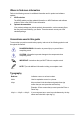
Where to find more information Refer to the following sources for additional information and for product and software updates. 1. ASUS websites The ASUS website provides updated information on ASUS hardware and software products. Refer to the ASUS contact information. 2. Optional documentation Your product package may include optional documentation, such as warranty flyers, that may have been added by your dealer. These documents are not part of the standard package.
Package contents Check your motherboard package for the following items. Motherboard ASUS PRIME A320M-K motherboard Cables 2 x Serial ATA 6.0 Gb/s cables Accessories 1 x I/O shield 1 x M.2 screw package Application DVD 1 x Support DVD Documentation 1 x User Manual If any of the above items is damaged or missing, contact your retailer.
PRIME A320M-K specifications summary AMD A320 Chipset - 4 x Serial ATA 6.0 Gb/s connectors with RAID 0, RAID 1 and RAID 10 support Storage AMD Ryzen™ processors: - 1 x M.2 socket 3 with M Key, Type 2242/2260/2280 (PCIe 3.0 x4 and SATA modes) storage devices support AMD 7th Generation A-series / Athlon™ processors: - 1 x M.2 socket 3 with M Key, Type 2242/2260/2280 (SATA mode) storage devices support AMD Ryzen™ / 7th Generation A-series / Athlon™ processors - 4 x USB 3.
PRIME A320M-K specifications summary 1 x PS/2 keyboard port (purple) 1 x PS/2 mouse port (green) 1 x HDMI port Rear panel I/O ports 1 x D-Sub port 1 x LAN (RJ-45) port 2 x USB 2.0/1.1 ports 4 x USB 3.1 Gen 1 ports 3 x Audio jacks support 8-channel audio output 1 x USB 3.1 Gen 1 connector supports additional 2 USB 3.1 Gen 1 ports 2 x USB 2.0/1.1 connectors support additional 4 USB 2.0/1.1 ports 1 x M.2 socket 3 for M Key and type 2242/2260/2280 devices 4 x SATA 6.
1 Product introduction Motherboard overview • Unplug the power cord from the wall socket before touching any component. • Before handling components, use a grounded wrist strap or touch a safely grounded object or a metal object, such as the power supply case, to avoid damaging them due to static electricity. • Before you install or remove any component, ensure that the ATX power supply is switched off or the power cord is detached from the power supply.
ATX power connectors (24-pin EATXPWR, 4-pin ATX12V) These connectors are for ATX power supply plugs. The power supply plugs are designed to fit these connectors in only one orientation. Find the proper orientation and push down firmly until the connectors completely fit. • For a fully configured system, we recommend that you use a power supply unit (PSU) that complies with ATX 12 V Specification 2.0 (or later version) and provides a minimum power of 350 W. This PSU type has 24-pin and 4-pin power plugs.
AMD A320 Serial ATA 6.0Gb/s connectors (7-pin SATA6G_1~4) These connectors connect to Serial ATA 6.0 Gb/s hard disk drives via Serial ATA 6.0 Gb/s signal cables. System panel connector (10-1 pin F_PANEL) This connector supports several chassis-mounted functions. Speaker connector (4-pin SPEAKER) This 4-pin connector is for the chassis-mounted system warning speaker. The speaker allows you to hear system beeps and warnings. USB 3.
SPDIFOUT GND This connector is for an additional Sony/Philips Digital Interface (S/PDIF) port. Connect the S/ PDIF Out module cable to this connector, then install the module to a slot opening at the back of the system chassis. +5V Digital audio connector (4-1 pin SPDIF_OUT) PIN 1 SPDIF_OUT Front panel audio connector (10-1 pin AAFP) This connector is for a chassis-mounted front panel audio I/O module that supports either HD Audio or legacy AC`97 audio standard.
• For RyzenTM processors A B C D E F G PCIEx16_1 – – – – – – shared – PCIEx1_1 shared – – – – – – – PCIEx1_2 M.2 APU USB3.
1.2.2 Rear panel connectors 2 1 10 3 4 9 5 6 7 3 8 1. PS/2 Mouse (green) port. This port is for a PS/2 mouse. 2. Video Graphics Adapter (VGA) port. This 15-pin port is for a VGA monitor or other VGA-compatible devices. 3. USB 3.1 Gen 1 ports. These two 9-pin Universal Serial Bus (USB) ports connect to USB 3.1 Gen 1 devices. • USB 3.1 Gen 1 devices can only be used for data storage. • Due to the design of AMD AM4 series chipset, all USB devices connected to the USB 2.0 and USB 3.
6. Line In port (light blue). This port connects to the tape, CD, DVD player, or other audio sources. 7. Line Out port (lime). This port connects to a headphone or a speaker. In the 4.1, 5.1and 7.1-channel configurations, the function of this port becomes Front Speaker Out. 8. Microphone port (pink). This port connects to a microphone. Refer to the audio configuration table for the function of the audio ports in 2.1, 4.1, 5.1, or 7.1-channel configuration. Audio 2.1, 4.1, 5.1 or 7.
Central Processing Unit (CPU) The motherboard comes with an AMD AM4 socket designed for AMD Ryzen™ / 7th Generation A-series / Athlon™ processors. Unplug all power cables before installing the CPU. The AM4 socket has a different pinout from the FM2+/FM2 socket. Ensure that you use a CPU designed for the AM4 socket. The CPU fits in only one correct orientation.
System memory Overview This motherboard comes with two Double Data Rate 4 (DDR4) Dual Inline Memory Module (DIMM) sockets. The figure illustrates the location of the DDR4 DIMM sockets: DIMM_A1 DIMM_B1 Channel Sockets Channel A DIMM_A1 Channel B DIMM_B1 • You may install varying memory sizes in Channel A and Channel B. The system maps the total size of the lower-sized channel for the dual-channel configuration.
Installing a DIMM 2 1 A A B To remove a DIMM A B 1-10 Chapter 1: Product introduction
BIOS information • Scan the QR code to view the BIOS update guide. • Before using the ASUS CrashFree BIOS 3 utility, rename the BIOS file in the removable device into PRA320MK.CAP. 2 BIOS setup program Use the BIOS Setup program to update the BIOS or configure its parameters. The BIOS screens include navigation keys and brief online help to guide you in using the BIOS Setup program.
EZ Mode By default, the EZ Mode screen appears when you enter the BIOS setup program. The EZ Mode provides you an overview of the basic system information, and allows you to select the display language, system performance mode, fan profile and boot device priority. To access the Advanced Mode, click Advanced Mode(F7) or press . The default screen for entering the BIOS setup program can be changed.
Advanced Mode The Advanced Mode provides advanced options for experienced end-users to configure the BIOS settings. The figure below shows an example of the Advanced Mode. Refer to the following sections for the detailed configurations. To access the EZ Mode, click EzMode(F7) or press .
Search on FAQ Move your mouse over this button to show a QR code. Scan this QR code with your mobile device to connect to the ASUS BIOS FAQ web page. You can also scan the QR code below. Exit menu The Exit menu items allow you to load the optimal default values for the BIOS items, and save or discard your changes to the BIOS items. Load Optimized Defaults This option allows you to load the default values for each of the parameters on the Setup menus.
Appendix Notices Federal Communications Commission Statement This device complies with Part 15 of the FCC Rules. Operation is subject to the following two conditions: • This device may not cause harmful interference. • This device must accept any interference received including interference that may cause undesired operation. This equipment has been tested and found to comply with the limits for a Class B digital device, pursuant to Part 15 of the FCC Rules.
IC: Canadian Compliance Statement Complies with the Canadian ICES-003 Class B specifications. This device complies with RSS 210 of Industry Canada. This Class B device meets all the requirements of the Canadian interference-causing equipment regulations. This device complies with Industry Canada license exempt RSS standard(s).
REACH Complying with the REACH (Registration, Evaluation, Authorisation, and Restriction of Chemicals) regulatory framework, we published the chemical substances in our products at ASUS REACH website at http://csr.asus.com/english/REACH.htm. DO NOT throw the motherboard in municipal waste. This product has been designed to enable proper reuse of parts and recycling.
English ASUSTeK Computer Inc. hereby declares that this device is in compliance with the essential requirements and other relevant provisions of related Directives. Full text of EU declaration of conformity is available at: www.asus.com/support Français AsusTek Computer Inc. déclare par la présente que cet appareil est conforme aux critères essentiels et autres clauses pertinentes des directives concernées. La déclaration de conformité de l’UE peut être téléchargée à partir du site Internet suivant : www.
ASUS contact information ASUSTeK COMPUTER INC. Address Telephone Fax Web site Technical Support Telephone Fax Online support 4F, No. 150, Li-Te Road, Peitou, Taipei 112, Taiwan +886-2-2894-3447 +886-2-2890-7798 www.asus.com +86-21-38429911 +86-21-5866-8722, ext. 9101# http://qr.asus.com/techserv ASUS COMPUTER INTERNATIONAL (America) Address 800 Corporate Way, Fremont, CA 94539, USA Telephone +1-510-739-3777 Fax +1-510-608-4555 Web site http://www.asus.
DECLARATION OF CONFORMITY Per FCC Part 2 Section 2. 1077(a) Asus Computer International Responsible Party Name: 800 Corporate Way, Fremont, CA 94539. Address: Phone/Fax No: (510)739-3777/(510)608-4555 hereby declares that the product Product Name : Motherboard Model Number : PRIME A320M-K Conforms to the following specifications: FCC Part 15, Subpart B, Unintentional Radiators Supplementary Information: This device complies with part 15 of the FCC Rules.