BIOS Manual Motherboard PRIME / ProArt / TUF GAMING AMD 600 Series
E21327 Revised Edition V2 October 2022 Copyright© 2022 ASUSTeK COMPUTER INC. All Rights Reserved. No part of this manual, including the products and software described in it, may be reproduced, transmitted, transcribed, stored in a retrieval system, or translated into any language in any form or by any means, except documentation kept by the purchaser for backup purposes, without the express written permission of ASUSTeK COMPUTER INC. (“ASUS”).
Contents 1. Knowing BIOS................................................................................................ 4 2. BIOS setup program...................................................................................... 5 2.1 EZ Mode......................................................................................... 6 2.2 Advanced Mode.............................................................................. 7 2.3 Qfan Control......................................................
BIOS Setup 1. Knowing BIOS The new ASUS UEFI BIOS is a Unified Extensible Interface that complies with UEFI architecture, offering a user-friendly interface that goes beyond the traditional keyboardonly BIOS controls to enable a more flexible and convenient mouse input. You can easily navigate the new UEFI BIOS with the same smoothness as your operating system. The term “BIOS” in this user manual refers to “UEFI BIOS” unless otherwise specified.
2. BIOS setup program Use the BIOS Setup to update the BIOS or configure its parameters. The BIOS screen include navigation keys and brief onscreen help to guide you in using the BIOS Setup program. Entering BIOS at startup To enter BIOS Setup at startup, press or during the Power-On Self Test (POST). If you do not press or , POST continues with its routines. Entering BIOS Setup after POST To enter BIOS Setup after POST: • Press ++ simultaneously.
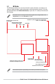
2.1 EZ Mode The EZ Mode provides you an overview of the basic system information, and allows you to select the display language, system performance, mode and boot device priority. To access the Advanced Mode, select Advanced Mode(F7) or press the hotkey for the advanced BIOS settings. The default screen for entering the BIOS setup program can be changed. Refer to the Setup Mode item in section Boot menu for details. Displays the system properties of the selected mode.
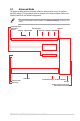
2.2 Advanced Mode The Advanced Mode provides advanced options for experienced end-users to configure the BIOS settings. The figure below shows an example of the Advanced Mode. Refer to the following sections for the detailed configurations. To switch from EZ Mode to Advanced Mode, click Advanced Mode(F7) or press the hotkey.
Menu bar The menu bar on top of the screen has the following main items: My Favorites For saving the frequently-used system settings and configuration. Main For changing the basic system configuration Ai Tweaker For changing the overclocking settings Advanced For changing the advanced system settings Monitor For displaying the system temperature, power status, and changing the fan settings.
AURA(F4) This button allows you to turn the RGB LED lighting or functional LED on or off. You may also access this item by pressing the key on the keyboard. [All On]: All LEDs (Aura or Functional) will be enabled. [Stealth Mode]: All LEDs (Aura and Functional) will be disabled. [Aura Only]: Aura LEDs will be enabled and functional LEDs will be disabled. [Aura Off]: Aura LEDs will be disabled, however functional LEDs will still be enabled.
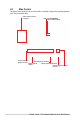
2.3 Qfan Control The Qfan Control allows you to set a fan profile or manually configure the operating speed of your CPU and chassis fans.
Configuring fans manually Select Manual from the list of profiles to manually configure your fans’ operating speed. Speed points Select to manually configure your fans To configure your fans: 1. Select the fan that you want to configure and to view its current status. 2. Click and drag the speed points to adjust the fans’ operating speed. 3. Click Apply to save the changes then click Exit (ESC).
3. My Favorites My Favorites is your personal space where you can easily save and access your favorite BIOS items. You can personalize this screen by adding or removing items.
Adding items to My Favorites To add BIOS items: 1. Press on your keyboard or click MyFavorite from the BIOS screen to open Setup Tree Map screen. 2. On the Setup Tree Map screen, select the BIOS items that you want to save in My Favorites screen. Main menu panel Selected shortcut items Submenu panel Delete all favorite items Recover to default favorite items 3. Select an item from main menu panel, then click the submenu that you want to save or press on your keyboard.
4. Main menu The Main menu screen appears when you enter the Advanced Mode of the BIOS Setup program. The Main menu provides you an overview of the basic system information, and allows you to set the system date, time, language, and security settings. Security The Security menu items allow you to change the system security settings.
• If you have forgotten your BIOS password, erase the CMOS Real Time Clock (RTC) RAM to clear the BIOS password. See the motherboard for information on how to erase the RTC RAM via the Clear CMOS header or button. • The Administrator or User Password items on top of the screen show the default [Not Installed]. After you set a password, these items show [Installed].
5. Ai Tweaker menu The Ai Tweaker menu items allow you to configure overclocking-related items. Be cautious when changing the settings of the Ai Tweaker menu items. Incorrect field values can cause the system to malfunction. The configuration options for this section vary depending on the CPU and DIMM model you installed on the motherboard. Scroll down to display other BIOS items.
Ai Overclock Tuner [Auto] Loads the optimal settings for the system. [Manual] When the manual mode is selected, the BCLK (base clock) frequency can be assigned manually. [EXPO I] Load the DIMM’s default EXPO memory timings (CL, TRCD, TRP, TRAS) and other memory parameters optimized by ASUS. [EXPO II] Load the DIMM’s complete default EXPO profile. Load the memory parameters profile optimized by ASUS if no DIMM profiles detected.
DRAM Frequency Forces a DDR5 frequency slower than the common tCK detected via SPD. Configuration options: [Auto] [DDR5-2000MHz] - [DDR5-20000MHz] FCLK Frequency Allows you to specify the FCLK frequency. Configuration options: [Auto] [800MHz] - [3000MHz] Core Performance Boost Automatically overclocks the CPU and DRAM to enhance system performance. Configuration options: [Auto] [Enabled] [Disabled] CPU Core Ratio Allows you to set the CPU core ratio. Configuration options: [Auto] [12.00] - [100.
Hysteresis Higher numbers increase the time required to persist in state when crossing thresholds before switching. Set to 0 for fastest reaction and increase this to require longer times to remain said state before activation. Configuration options: [Auto] [0] - [255] DRAM Timing Control The sub-items in this menu allow you to set the DRAM timing control features. Use the <+> and <-> keys to adjust the value. To restore the default setting, type [Auto] using the keyboard and press the key.
Tfaw Configuration options: [Auto] [1] - [127] DRAM WRITE to READ Delay L Configuration options: [Auto] [1] - [127] DRAM WRITE to READ Delay S Configuration options: [Auto] [1] - [31] TrdrdScl Configuration options: [Auto] [1] - [15] TrdrdSc Configuration options: [Auto] [1] - [15] TrdrdSd Configuration options: [Auto] [1] - [15] Trdrddd Configuration options: [Auto] [1] - [15] TwrwrScl Configuration options: [Auto] [1] - [63] TwrwrSc Configuration options: [Auto] [1] - [15] TwrwrSd Configuration options: [
Rtt Park Configuration options: [Auto] [RTT_OFF] [RZQ (240)] [RZQ/2 (120)] [RZQ/3 (80)] [RZQ/4 (60)] [RZQ/6 (40)] [RZQ/7 (34)] Rtt Park Dqs Configuration options: [Auto] [RTT_OFF] [RZQ (240)] [RZQ/2 (120)] [RZQ/3 (80)] [RZQ/4 (60)] [RZQ/5 (48)] [RZQ/6 (40)] [RZQ/7 (34)] ProcODT Configuration options: [Auto] [High Impedance] [480 ohm] [240 ohm] [160 ohm] [120 ohm] [96 ohm] [80 ohm] [68 ohm] [60 ohm] [53 ohm] [48 ohm] [43 ohm] [40 ohm] [36 ohm] [34 ohm] [32 ohm] [30 ohm] [28 ohm] [26 ohm] [25 ohm] Proc Data D
SOC EDC Limit SOC EDC Limit [A], Board electrically constrained current delivery capacity, adjustable up to motherboard’s programmed board SOC EDC limit. Configuration options: [Auto] [0] - [65535] Precision Boost Overdrive Scalar [Auto] Part runs with a scalar of 1X, i.e. normal operation. [Manual] Part runs with a scalar of customized value. The following item appears only when Precision Boost Overdrive Scalar is set to [Manual].
Curve Optimizer Curve Optimizer Allows the user to shift the Voltage / Frequency (AVFS) curve to include higher voltages (positive values) or lower voltages (negative values). The larger the value entered the larger the magnitude of the voltage limit. Configuration options: [Auto] [All Cores] [Per Core] The following items appear only when Curve Optimizer is set to [All Cores]. All Core Curve Optimizer Sign Determines the direction of the curve shift on all cores.
Digi+ VRM VRM Initialization Check When any error occurs during VRM initialization, the system will hang at POST code 76/77 if this function is enabled. Configuration options: [Disabled] [Enabled] CPU Load-line Calibration CPU Load-Line Calibration is defined by AMD VRM spec and affects CPU voltage. The CPU working voltage will decrease proportionally to CPU loading. Higher value could get higher voltage and good overclocking performance but increase the CPU and VRM thermal.
CPU Power Phase Control Allows you to set the power phase control of the CPU. [Auto] Automatically selects the power phase control. [Standard] The number of active phases is controlled by the CPU. [Optimized] Set to the ASUS optimized phase tuning profile. [Extreme] Sets full phase mode. [Manual] Manually select the power phase response speed. DO NOT remove the thermal module when setting this item to [Extreme]. The thermal conditions should be monitored.
The following item appears only when VDDSOC Power Phase Control is set to [Manual]. Power Phase Response Select ultra fast mode for a faster power phase response. The reaction time will be longer when regular mode is selected. Configuration options: [Ultra Fast] [Fast] [Medium] [Regular] Performance Bias Different Values may help different Software’s performance.
Custom Algorithms Customize your own algorithms to adjust boosting behavior for more optimized power efficiency, temperatures, and performance. Customize up to 3 concurrent algorithms. Algorithm 1-3 Set to [Enabled] to customize this algorithm. Configuration options: [Auto] [Enabled] [Disabled] The following items appear only when Algorithm 1 is set to [Enabled]. Algorithm 1-3 Condition Select the condition to monitor for and take action upon.
CPU Core Voltage Allows you to increase to help CPU Core Frequency overclock. Configuration options: [Auto] [Manual Mode] [Offset Mode] The following item appears only when CPU Core Voltage is set to [Manual Mode]. CPU Core Voltage Override Allows you to configure the input voltage for the CPU by the external voltage regulator. Use the <+> and <-> keys to adjust the value. The values range from 0.625V to 1.700V with an interval of 0.005V. Configuration options: [Auto] [0.62500] - [1.
CPU VDDIO / MC Voltage Use the <+> or <-> to adjust the value. The values range from 0.800V to 2.000V with an interval of 0.010V. Configuration options: [Auto] [0.80000] - [2.00000] Misc Voltage Configuration options: [Auto] [Offset Mode] The following items appear only when Misc Voltage is set to [Offset Mode]. Offset Mode Sign [+] [–] To offset the Misc voltage by a positive value. To offset the Misc voltage by a negative value. Misc Voltage Offset Use the <+> or <-> to adjust the value.
The following items appear only when PMIC Voltages is set to [Sync All PMICs]. SPD HUB VLDO (1.8V) Allows you to set the main power for the SPD Hub Logic. Default set to 1.8V. Use the <+> or <-> to adjust the value. The values range from 1.700V to 2.000V with an interval of 0.100V. Configuration options: [Auto] [1.70000] - [2.00000] SPD HUB VDDIO (1.0V) Allows you to set the main power for the SPD Hub side-band interface. Default set to 1.0V. Use the <+> or <-> to adjust the value. The values range from 0.
6. Advanced menu The Advanced menu items allow you to change the settings for the CPU and other system devices. Scroll down to display other BIOS items. Be cautious when changing the settings of the Advanced menu items. Incorrect field values can cause the system to malfunction.
6.1 Trusted Computing The items in this menu allow you to configure the Trusted Computing settings. Security Device Support Allows you to enable or disable the BIOS support for security device. O.S. will not show Security Device. TCG EFI protocol and INT1A interface will not be available. Configuration options: [Disable] [Enable] The following items appear only when Security Device Support is set to [Enable]. SHA256 PCR Bank Allows you to enable or disable the SHA256 PCR Bank.
Physical Presence Spec Version Allows you to select to Tell O.S. to support PPI Version 1.2 or 1.3. Configuration options: [1.2] [1.3] Some HCK tests might not support 1.3. 6.2 AMD fTPM configuration The items in this menu show the AMD fTPM configuration options. Firmware TPM switch Allows you to enable or disable Firmware TPM. [Enable Firmware TPM] Enables platform Firmware TPM. [Disable Firmware TPM] Disables platform Firmware TPM.
6.3 AMD CBS The items in this menu shows the AMD Common BIOS Specifications. The configuration options for this section vary depending on the motherboard. Please refer to the BIOS of your motherboard for the actual settings and options. Global C-state Control Allows you to control IO based C-state generation and DF C-states. Configuration options: [Disabled] [Enabled] [Auto] IOMMU Allows you to enable or disable IOMMU.
Prefetcher settings L1 Stream HW Prefetcher Allows you to enable or disable L1 Stream HW Prefetcher. Configuration options: [Disable] [Enable] [Auto] L2 Stream HW Prefetcher Allows you to enable or disable L2 Stream HW Prefetcher. Configuration options: [Disable] [Enable] [Auto] L1 Stride Prefetcher Uses memory access history of individual instructions to fetch additional lines when each access is a constant distance from the previous.
Local APIC MOde Allows you to select local APIC operation modes. Configuration options: [Compatibility] [xAPIC] [x2APIC] [Auto] ACPI _CST C1 Declaration Determines whether or not to declare the C1 state to the OS. Configuration options: [Disabled] [Enabled] [Auto] MCA error thresh enable Allows you to enable MCA error thresholding. Configuration options: [False] [True] [Auto] The following item appears only when MCA error thresh enable is set to [True].
SNP Memory (RMP Table) Coverage When this item is set to [Enabled], the ENTIE system memory is covered. Configuration options: [Disabled] [Enabled] [Custom] [Auto] The following item appears only when SNP Memory (RMP Table) Coverage is set to [Custom]. Amount of Memory to Cover Specify MB of System Memory to be covered in Hex. Configuration options: [0] - [100000] SMEE Control secure memory enryption enable.
Disable DF sync flood propagation Disables propagation from PIE to other DF components and eventually to SDP ports. Configuration options: [Sync flood disabled] [Sync flood enabled] [Auto] Disable DF sync flood propagation Disables propagation from PIE to other DF components and eventually to SDP ports.
Trcd Ctrl [Auto] [Manual] Follow default setting. Manually specify. The following item appears only when Trcd Ctrl is set to [Manual]. Trcd Specifies the RAS# Active to CAS# Read Delay Time. Valid values: 0x8 ~ 0x3E with a stepping of 2. The value is in hex. Trp Ctrl [Auto] [Manual] Follow default setting. Manually specify. The following item appears only when Trp Ctrl is set to [Manual]. Trp Specifies Row Precharge Delay Time. Valid values: 0x8 ~ 0x3E with a stepping of 2. The value is in hex.
The following item appears only when Trfc1 Ctrl is set to [Manual]. Trfc1 Specifies the Refresh Recovery Delay Time (tRFC1). Valid values: 0x32 ~ 0xFFF. The value is in hex. Trfc2 Ctrl [Auto] [Manual] Follow default setting. Manually specify. The following item appears only when Trfc2 Ctrl is set to [Manual]. Trfc2 Specifies the Refresh Recovery Delay Time (tRFC2). Valid values: 0x32 ~ 0xFFF. The value is in hex. TrfcSb Ctrl [Auto] [Manual] Follow default setting. Manually specify.
The following item appears only when TrrdS Ctrl is set to [Manual]. TrrdS Specifies the Activate to Activate Delay Time, different bank group (tRRD_S). Valid values: 0x4 ~ 0x14. The value is in hex. Tfaw Ctrl [Auto] [Manual] Follow default setting. Manually specify. The following item appears only when Tfaw Ctrl is set to [Manual]. Tfaw Specifies the Four Activate Window Time. Valid values: 0x14 ~ 0x50. The value is in hex. TwtrL Ctrl [Auto] [Manual] Follow default setting. Manually specify.
TrdrdSd Ctrl [Auto] [Manual] Follow default setting. Manually specify. The following item appears only when TrdrdSd Ctrl is set to [Manual]. TrdrdSd Specifies the Read to Read turnaround timing in the same DIMM. Valid values: 0x1 ~ 0xF. The value is in hex. TrdrdDd Ctrl [Auto] [Manual] Follow default setting. Manually specify. The following item appears only when TrdrdDd Ctrl is set to [Manual]. TrdrdDd Specifies the Read to Read turnaround timing in a different DIMM. Valid values: 0x1 ~ 0xF.
The following item appears only when TwrwrDd Ctrl is set to [Manual]. TwrwrDd Specifies the Write to Write turnaround timing in a different DIMM. Valid values: 0x1 ~ 0xF. The value is in hex. Twrrd Ctrl [Auto] [Manual] Follow default setting. Manually specify. The following item appears only when Twrrd Ctrl is set to [Manual]. Twrrd Specifies the Write to Read turnaround timing. Valid values: 0x1 ~ 0xF. The value is in hex. Trdwr Ctrl [Auto] [Manual] Follow default setting. Manually specify.
DRAM ODT impedance DQS_RTT_PARK Specifies the DRAM ODT impedance DQS_RTT_PARK. Configuration options: [Auto] [RTT_OFF] [RZQ (240)] [RZQ/2 (120)] [RZQ/3 (80)] [RZQ/4 (60)] [RZQ/5 (48)] [RZQ/6 (40)] [RZQ/7 (34)] Processor ODT impedance Specifies the Processor ODT impedance. Configuration options: [Auto] [High Impedance] [480 ohm] [240 ohm] [160 ohm] [120 ohm] [96 ohm] [80 ohm] [68 ohm] [60 ohm] Processor DQ drive strengths Specifies the Processor DQ drive strengths.
DRAM PDA Enumerate ID Programming Mode Configuration options: [Auto] [Sequential PDA enumeration mode] [Legacy PDA enumeration mode] DDR Memory MBIST This item allows you to configure DDR Memory MBIST. MBIST Enable Allows you to enable or disable Memory MBIST. Configuration options: [Disabled] [Enabled] [Auto] The following items appear only when MBIST Enable is set to [Enabled].
PSPP Policy Configuration options: [Disabled] [Balanced] [Auto] GFX Configuration This item allows you to configure GFX Configuration. UMA Version [Legacy] [Non-Legacy] [Auto] UMA Legacy Version UMA Non-Legacy Version Hybrid Secure GPU Host Translation Cache Allows you to enable or disable GPU Host Translation Cache. Configuration options: [Disabled] [Enabled] [Auto] Audio Configuration This item allows you to configure Audio Configuration.
TDC Control [Auto] [Manual] Use the default TDC Limits. User can set customized TDC Limits. The following item appears only when TDC Control is set to [Manual]. TDC_VDDCR_VDD Allows you to set the VDDCR_VDD TDC Limit [mA] (IRM limit will be enforced). EDC Control [Auto] [Manual] Use the default EDC Limits. User can set customized EDC Limits. The following item appears only when EDC Control is set to [Manual]. TDC_VDDCR_VDD Allows you to set the VDDCR_VDD EDC Limit [mA] (IRM limit will be enforced).
Low Pwm Configuration options: [0] - [100] Medium Pwm Configuration options: [0] - [100] High Pwm Configuration options: [0] - [100] Temperature Hysteresis Allows you to set the temperature hysteresis [‘C]. Configuration options: [0] - [255] PWM Frequency [Auto] Sets to the default option [1] 100Hz 25kHz [0] Fan Polarity [Auto] Sets to the default option [1] Positive [0] Negative VDDP Voltage Control [Auto] [Manual] Use the default VDDP Voltage. User can set custom VDDP Voltage.
6.4 CPU Configuration The items in this menu show the CPU-related information that the BIOS automatically detects. Scroll down to display other BIOS items. The items in this menu may vary based on the CPU installed. PSS Support Allows you to enable or disable the generation of ACPI_PPC, and _PCT objects. Configuration options: [Disabled] [Enabled] NX Mode Allows you enable or disable No-execute page protection Function.
6.5 PCI Subsystem Settings The items in this menu allow you to configure PCI, PCI-X, and PCI Express settings. Above 4G Decoding Allows you to enable or disable 64bit capable Devices to be Decoded in Above 4G Address Space (Only if System supports 64 bit PCI Decoding). Configuration options: [Disabled] [Enabled] • Only enabled under 64bit operating system. • The following item appears only when Above 4G Decoding is set to [Enabled].
6.6 USB Configuration The items in this menu allow you to change the USB-related features. The Mass Storage Devices item shows the auto-detected values. If no USB device is detected, the item shows None. Legacy USB Support [Enabled] Your system supports the USB devices in legacy operating systems. [Disabled] Your USB devices can be used for BIOS setup only and cannot be recognized in the boot devices list. [Auto] Your system automatically detects the presence of USB devices at startup.
USB Single Port Control Allows you to enable or disable the individual USB ports. Refer to section Motherboard layout and Rear I/O connection in your motherboard’s user guide for the location of the USB ports. 6.7 Network Stack Configuration The items in this menu allow you to change the Network Stack Configuration. Network stack Allows you to disable or enable the UEFI network stack. Configuration options: [Disabled] [Enabled] The following items appear only when Network Stack is set to [Enabled].
6.9 HDD/SSD SMART Information The items in this menu allow you to view the SMART information for connected storage devices. The options displayed in this menu may vary depending on the devices connected to your motherboard. Please refer to the BIOS of your motherboard for the actual settings and options. NVM Express devices do not support SMART information.
6.10 SATA Configuration While entering Setup, the BIOS automatically detects the presence of SATA devices. The SATA Port items show Empty if no SATA device is installed to the corresponding SATA port. Scroll down to display the other BIOS items. The settings and options of this menu may vary depending on your motherboard. Please refer to the BIOS of your motherboard for the actual settings and options. SATA Controller(s) Allows you to enable or disable the SATA Device.
SMART Self Test S.M.A.R.T. (Self-Monitoring, Analysis and Reporting Technology) is a monitoring system that shows a warning message during POST (Power-on Self Test) when an error occurs in the hard disks. Configuration options: [Disabled] [Enabled] SATA6G_1 - SATA6G_4 Allows you to enable or disable the selected SATA port. Configuration options: [Disabled] [Enabled] SATA6G_1 - SATA6G_4 Hot Plug Designates this port as Hot Pluggable. Configuration options: [Disabled] [Enabled] 6.
Power On By PCI-E Allows you to enable or disable the Wake-on-LAN function of the onboard LAN controller or other installed PCI-E LAN cards. Configuration options: [Disabled] [Enabled] Power On By RTC Allows you to enable or disable the RTC (Real-Time Clock) to generate a wake event and configure the RTC alarm date. When enabled, you can set the days, hours, minutes, or seconds to schedule an RTC alarm date. Configuration options: [Disabled] [Enabled] 6.
PCIEX16_2 Bandwidth Bifurcation Configuration [PCIE X8 Mode] Switch PCIEX16_2 to x8. [PCIE RAID Mode] Up to 2 SSDs installed onto the Hyper M.2 X16 Series card can be detected. Use [PCIE RAID Mode] when installing the Hyper M.2 X16 series card or other M.2 adapter cards. Installing other devices may result in a boot-up failure. The number of SSDs supported varies with the PCIe bifurcation abilities enabled by each processor. HD Audio Controller Allows you to enable or disable Azalia HD Audio.
10G LAN Card Allows you to enable or disable the 10G LAN card. Configuration options: [Disabled] [Enabled] USB power delivery in Soft Off state (S5) Allows you to enable or disable USB power when your PC is in the S5 state. Configuration options: [Disabled] [Enabled] Serial Port Configuration This submenu allows you to set parameters for Serial Port. This item will only function if there is a serial port (COM) connector on your motherboard. Serial Port Allows you to enable or disable the Serial port.
Chipset_2 Link Mode Allows you to set the link speed between Chipset_1 and Chipset_2. Configuration options: [Auto] [GEN 1] [GEN 2] [GEN 3] [GEN 4] M.2_3 Link Mode Allows you to set the link speed for M.2_3 Device. Configuration options: [Auto] [GEN 1] [GEN 2] [GEN 3] [GEN 4] PCIEX16 Link Mode Allows you to set the link speed for PCIEX16 Slot. Configuration options: [Auto] [GEN 1] [GEN 2] [GEN 3] [GEN 4] 6.13 NB Configuration The items in this menu allow you to change the NB Configurations.
6.14 AMD PBS The items in this menu shows the AMD PBS Setup page. Graphics Features This submenu allows you to configure Graphics Featurs - HG, DGPU Features and BOMACO configurations. Special Display Features Allows you to enable or disable HybridGraphics. Configuration options: [Disabled] [HybridGraphics] D3Cold Support Allows you to enable or disable PCIe x8 Slot D3Cold.
Discrete GPU HPD Circuitry Allows you to enable or disable Discrete GPU Display HPD Circuitry. Configuration options: [OR Circuitry] [Pulse Circuitry] Discrete GPU’s Audio Allows you to disable Discrete GPU’s Audio or keep its ROM strap setting. Configuration options: [Disabled] [Keep ROM Strap Setting] Discrete GPU’s USB Port Allows you to disable Discrete GPU’s USB Port or keep default setting.
6.15 AMD Overclocking The items in this menu shows the AMD Overclocking Setup page. The configuration options for this section vary depending on the motherboard. Please refer to the BIOS of your motherboard for the actual settings and options. Damage caused by use of your AMD processor outside of specification or in excess of factory settings are not covered by your system manufacturers warranty. The following items appear only when [Accept] is selected for DRAM Timing Configuration.
Bit Map Down Core Apply Changes Check and apply changes, need to make sure core number is equaled in each CCD. SMT Control Can be used to disable symmetric multithreading. To re-enable SMT, a POWER CYCLE is needed after selecting the [Auto] option. Configuration options: [Auto] [Disable] S3 is NOT SUPPORTED on systems where SMT is disabled.
Tras Ctrl [Auto] [Manual] Follow default setting. Manually specify. The following item appears only when Tras Ctrl is set to [Manual]. Tras Specifies Active to Precharge Delay Time. Valid values: 0x1E ~ 0x7E with a stepping of 2. Trc Ctrl [Auto] [Manual] Follow default setting. Manually specify. The following item appears only when Trc Ctrl is set to [Manual]. Trc Specifies Active to Active/Refresh Delay Time. Valid values: 0x20 ~ 0xFF. The value is in hex.
The following item appears only when TrfcSb Ctrl is set to [Manual]. TrfcSb Specifies the Refresh Recovery Delay Time (tRFCSB). Valid values: 0x32 ~ 0x7FF. The value is in hex. Trtp Ctrl [Auto] [Manual] Follow default setting. Manually specify. The following item appears only when Trtp Ctrl is set to [Manual]. Trtp Specifies the Read CAS# to Precharge command delay time. Valid values: 0x5 ~ 0x1F. The value is in hex. TrrdL Ctrl [Auto] [Manual] Follow default setting. Manually specify.
TwtrS Ctrl [Auto] [Manual] Follow default setting. Manually specify. The following item appears only when TwtrS Ctrl is set to [Manual]. TwtrS Specifies the Minimum Write to Read Time, different bank group. Valid values: 0x2 ~ 0x10. The value is in hex. DDR Non-SPD Timing TrdrdScL Ctrl [Auto] [Manual] Follow default setting. Manually specify. The following item appears only when TrdrdScL Ctrl is set to [Manual]. TrdrdScL Specifies the CAS to CAS delay time, same bank group. Valid values: 0x1 ~ 0xF.
The following item appears only when TwrwrScL Ctrl is set to [Manual]. TwrwrScL Specifies the CAS to CAS Delay Time, same bank group. Valid values: 0x1 ~ 0x3F. The value is in hex. TwrwrSc Ctrl [Auto] [Manual] Follow default setting. Manually specify. The following item appears only when TwrwrSc Ctrl is set to [Manual]. TwrwrSc Specifies the Write to Write turnaround timing in the same chipselect. Valid values: 0x1 ~ 0xF. The value is in hex. TwrwrSd Ctrl [Auto] [Manual] Follow default setting.
DDR BUS Configuration Processor CA drive strengths Specifies the Processor CA drive strengths. Configuration options: [Auto] [120.0 Ohm] [60.0 Ohm] [40.0 Ohm] [30.0 Ohm] Processor DQ drive strengths Specifies the Processor DQ drive strengths. Configuration options: [Auto] [High Impedance] [240 ohm] [120 ohm] [80 ohm] [60 ohm] [48 ohm] [40 ohm] [34.3 ohm] Processor ODT impedance Specifies the Processor ODT impedance.
Precision Boost Overdrive Precision Boost Overdrive When this item is enabled, it allows the processor to run beyond defined values for PPT, VDD_CPU EDC, VDD_CPU TDC, VDD_SOC EDC, VDD_SOC TDC to the limits of the board, and allows it to boost at higher voltages for longer durations than default operation. Configuration options: [Auto] [Disabled] [Enabled] [Manual] The following items appear only when Precision Boost Overdrive is set to [Manual].
The following item appears only when CPU Boost Clock Override is set to [Enabled (Positive)]. Max CPU Boost Clock Override(+) Increases the maximum CPU frequency that may be automatically achieved by the Precision Boost 2 algorithm. Use the <+> or <-> to adjust the value. The values range from 25 to 200 with an interval of 25. Configuration options: [Auto] [0] - [200] The following item appears only when CPU Boost Clock Override is set to [Enabled (Negative)].
Curve Optimizer Curve Optimizer Allows the user to shift the Voltage / Frequency (AVFS) curve to include higher voltages (positive values) or lower voltages (negative values). The larger the value entered the larger the magnitude of the voltage limit. Configuration options: [Disable] [All Cores] [Per Core] The following items appear only when Curve Optimizer is set to [All Cores]. All Core Curve Optimizer Sign Determines the direction of the curve shift on all cores.
VDDP Voltage Control VDDP Voltage Control Allows the user to adjust the VDDP voltage. VDDP is system default. [Auto] [Manual] Set voltage for the DDR bus signaling (PHY). The following items appear only when VDDP Voltage Control is set to [Manual]. VDDP Voltage Adjust VDDP is a voltage for the DDR bus signaling (PHY), and it is dervied from your DRAM Voltage (VDDIO_Mem). As a result, VDDP voltage in mV can approach but not exceed your DRAM Voltage.
LCLK Frequency Control LCLK Frequency Control [Auto] Use default settings. [Manual] Manually configure LCLK frequency. The following item appears only when LCLK Frequency Control is set to [Manual]. Maximum Frequency Allows you to set the maximum LCLK frequency. Configuration options: [1029] - [2500] Onboard Voltage Control VDDIO Voltage Control VDDIO Ctrl Allows the user to adjust the VDDIO voltage. [Auto] Use the default VDDIO voltage. [Manual] Set DIMM VDD/VDDQ to synchronize to APU VDDIO.
The following item appears only when VPP Ctrl is set to [Manual]. VPP Adjust Adjust MEM VPP, stepping is 10mV. Range is from 1500mV to 2135mV.
7. Monitor menu The Monitor menu displays the system temperature/power status, and allows you to change the fan settings. Scroll down to display the other BIOS items. The settings and options of this menu may vary depending on your motherboard. Please refer to the BIOS of your motherboard for the actual settings and options.
Voltage Monitor CPU Core Voltage, 12V Voltage, 5V Voltage, 3.3V Voltage, CPU VDDIO / MC Voltage [x.xxx V] The onboard hardware monitor automatically detects the voltage output through the onboard voltage regulators. Select [Ignore] if you do not want to detect this item. Q-Fan Configuration Q-Fan Tuning Click this item to automatically detect the lowest speed and configure the minimum duty cycle for each fan. The process may take 2 to 5 minutes.
CPU Fan Speed Low Limit Allows you to set the lower speed limit for assigned fan/pump. A warning message will appear when the limit is reached; the warning message will not appear if [Ignore] is selected. Configuration options: [Ignore] [200 RPM] [300 RPM] [400 RPM] [500 RPM] [600 RPM] The following items appear only when CPU Fan Profile is set to [Manual].
CPU Fan Point1 Temperature When the temperature source is lower than the temperature of P1, the fan will operate at the duty cycle of P1. When the temperature source is higher than the temperature of P1, the duty cycle will be determined according to the P1-P2 and the temperature source. Use the <+> or <-> keys to adjust the Point1 temperature. CPU Fan Point1 Duty Cycle (%) When the temperature source is lower than the temperature of P1, the fan will operate at the duty cycle of P1.
The following items appear only when Chassis Fan 1-5 Profile is set to [Manual]. Chassis Fan 1-5 Point4 Temperature When the temperature source is lower than the temperature of P4, the duty cycle will be determined according to the P3-P4 and the temperature source. When the temperature source is higher than the temperature of P4, the fan will operate at the duty cycle of P4. Use the <+> or <-> keys to adjust the Point4 temperature.
AIO Pump Q-Fan Control Allows you to set the AIO Pump operating mode. [Auto Detect] Detects the type of installed fan/pump and automatically switches the control modes. [DC Mode] [PWM Mode] Enables the Q-Fan Control feature in DC mode for 3-pin fan/pump. Enables the Q-Fan Control feature in PWM mode for 4-pin fan/ pump. AIO Pump Profile Allows you to set the appropriate performance level of the assigned fan/pump.
AIO Pump Point4 Duty Cycle (%) When the temperature source is lower than the temperature of P4, the duty cycle will be determined according to the P3-P4 and the temperature source. When the temperature source is higher than the temperature of P4, the fan will operate at the duty cycle of P4. Use the <+> or <-> keys to adjust the Point4 temperature.
8. Boot menu The Boot menu items allow you to change the system boot options. CSM (Compatibility Support Module) Allows you to configure the CSM (Compatibility Support Module) items to fully support the various VGA, bootable devices and add-on devices for better compatibility. Launch CSM will be set to [Disabled] and cannot be configured when using the integrated graphics.
Boot from Storage Devices Allows you to select the type of storage devices that you want to launch. Configuration options: [Ignore] [Legacy only] [UEFI only] Boot from PCI-E/PCI Expansion Devices Allows you to select the type of PCI-E/PCI expansion devices that you want to launch. Configuration options: [Ignore] [Legacy only] [UEFI only] Secure Boot Allows you to configure the Windows® Secure Boot settings and manage its keys to protect the system from unauthorized access and malwares during POST.
Set New key Allows you to load the downloaded PK from a USB storage device. Delete key Allows you to delete the PK from your system. Once the PK is deleted, all the system’s Secure Boot keys will not be active. Configuration options: [Yes] [No] The PK file must be formatted as a UEFI variable structure with time-based authenticated variable. KEK Management The KEK (Key-exchange Key or Key Enrollment Key) manages the Signature database (db) and Revoked Signature database (dbx).
DBX Management The dbx (Revoked Signature database) lists the forbidden images of db items that are no longer trusted and cannot be loaded. Save to file Allows you to save the dbx to a USB storage device. Set New key Allows you to load the downloaded dbx from a USB storage device. Append Key Allows you to load the additional dbx from a storage device for an additional db and dbx loaded management. Delete key Allows you to delete the dbx file from your system.
The following item appears only when Boot Logo Display is set to [Disabled]. Post Report Allows you to select a desired POST report waiting time or until ESC is pressed. Configuration options: [1 sec] - [10 sec] [Until Press ESC] Boot up NumLock State Allows you to select the keyboard NumLock state. Configuration options: [On] [Off] Wait For ‘F1’ If Error Allows your system to wait for the key to be pressed when error occurs.
9. Tool menu The Tool menu items allow you to configure options for special functions. Select an item then press to display the submenu. BIOS Image Rollback Support [Enabled] Support roll back your BIOS to a previous version, but this setting violates the NIST SP 800-147 requirement. [Disabled] Only support updating your BIOS to a newer version, and this setting meets the NIST SP 800-147 requirement.
9.1 ASUS EZ Flash 3 Utility This item allows you to run ASUS EZ Flash 3. When you press , a confirmation message appears. Use the left/right arrow key to select between [Yes] or [No], then press to confirm your choice. For more details, refer to section ASUS EZ Flash 3. 9.2 ASUS Secure Erase SSD speeds may lower over time as with any storage medium due to data processing. Secure Erase completely and safely cleans your SSD, restoring it to factory performance levels.
9.3 ASUS User Profile This item allows you to store or load multiple BIOS settings. Load from Profile Allows you to load the previous BIOS settings saved in the BIOS Flash. Key in the profile number that saved your BIOS settings, press , and then select Yes. • DO NOT shut down or reset the system while updating the BIOS to prevent the system boot failure! • We recommend that you update the BIOS file only coming from the same memory/ CPU configuration and BIOS version.
9.4 ASUS SPD Information This item allows you to view the DRAM SPD information. 9.5 ASUS Armoury Crate This item allows you to enable or disable downloading and installing of the Armoury Crate app in the Windows® OS. The Armoury Crate app can help you manage and download the latest drivers and utilities for your motherboard.
9.6 MyASUS This item allows you to enable or disable downloading and installing of the MyASUS app in the Windows® OS. The availability of this menu, as well as the settings and options may vary depending on your motherboard. Please refer to the BIOS of your motherboard for the actual settings and options.
10. Exit menu The Exit menu items allow you to load the optimal default values for the BIOS items, and save or discard your changes to the BIOS items. You can access the EZ Mode from the Exit menu. Load Optimized Defaults This option allows you to load the default values for each of the parameters on the Setup menus. When you select this option or if you press , a confirmation window appears. Select OK to load the default values.
11. Updating BIOS The ASUS website publishes the latest BIOS versions to provide enhancements on system stability, compatibility,and performance. However, BIOS updating is potentially risky. If there is no problem using the current version of BIOS, DO NOT manually update the BIOS. Inappropriate BIOS updating may result to system’s failure to boot. Carefully follow the instructions in this chapter to update your BIOS when necessary. Visit http://www.asus.
11.2 ASUS CrashFree BIOS 3 The ASUS CrashFree BIOS 3 utility is an auto recovery tool that allows you to restore the BIOS file when it fails or gets corrupted during the updating process. You can restore a corrupted BIOS file using the motherboard support DVD or a USB flash drive that contains the BIOS file. The BIOS file in the motherboard support DVD may be older than the BIOS file published on the ASUS official website. If you want to use the newer BIOS file, download the file at https://www.asus.