Motherboard PRIME H410M-E
E16383 First Edition March 2020 Copyright © 2020 ASUSTeK COMPUTER INC. All Rights Reserved. No part of this manual, including the products and software described in it, may be reproduced, transmitted, transcribed, stored in a retrieval system, or translated into any language in any form or by any means, except documentation kept by the purchaser for backup purposes, without the express written permission of ASUSTeK COMPUTER INC. (“ASUS”).
Contents Safety information....................................................................................................... iv About this guide........................................................................................................... v Package contents........................................................................................................ vi PRIME H410M-E specifications summary.................................................................
Safety information Electrical safety • To prevent electrical shock hazard, disconnect the power cable from the electrical outlet before relocating the system. • When adding or removing devices to or from the system, ensure that the power cables for the devices are unplugged before the signal cables are connected. If possible, disconnect all power cables from the existing system before you add a device.
About this guide This user guide contains the information you need when installing and configuring the motherboard. How this guide is organized This guide contains the following parts: • Chapter 1: Product introduction This chapter describes the features of the motherboard and the new technology it supports. It includes descriptions of the switches, jumpers, and connectors on the motherboard.
Package contents Check your motherboard package for the following items. Motherboard 1 x PRIME H410M-E motherboard Cables 2 x SATA 6Gb/s cables Miscellaneous 1 x I/O Shield 1 x M.2 ANCHOR Application DVD 1 x Support DVD Documentation 1 x User manual If any of the above items is damaged or missing, contact your retailer.
PRIME H410M-E specifications summary Rear USB (Total 4 ports) 2 x USB 3.2 Gen 1 ports (2 x Type-A) USB 2 x USB 2.0 ports (2 x Type-A) Front USB (Total 6 ports) 1 x USB 3.2 Gen 1 header supports additional 2 USB 3.2 Gen 1 ports 2 x USB 2.0 headers support additional 4 USB 2.0 ports Realtek ALC887 7.
PRIME H410M-E specifications summary Special Features ASUS 5X PROTECTION III - ASUS DIGI+ VRM - ASUS LANGuard - ASUS Overvoltage Protection - ASUS SafeSlot Core - ASUS Stainless-Steel Back I/O ASUS Q-Design - ASUS Q-DIMM - ASUS Q-Slot ASUS Thermal Solution - Aluminum heatsink design ASUS Exclusive Software Armoury Crate AI Suite 3 - Performance And Power Saving Utility EPU Digi+ VRM Fan Xpert - EZ update Software Features AI Charger Norton Anti-virus software (Free Trial for 60 days) WinRAR UEFI BIOS AS
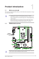
1 Product introduction 1.1 Before you proceed Take note of the following precautions before you install motherboard components or change any motherboard settings. 1.2 • Unplug the power cord from the wall socket before touching any component. • Before handling components, use a grounded wrist strap or touch a safely grounded object or a metal object, such as the power supply case, to avoid damaging them due to static electricity.
1.2.1 Layout contents 1. CPU socket The motherboard comes with a surface mount Intel® Socket LGA1200 designed for 10th Gen Intel® CoreTM, Pentium® Gold and Celeron® Processors. For more details, refer to Central Processing Unit (CPU). 2. DDR4 DIMM slots The motherboard comes with Dual Inline Memory Modules (DIMM) slots designed for DDR4 (Double Data Rate 4) memory modules. For more details, refer to System memory. 3. Expansion slots This motherboard supports one PCIe x16 graphic card and two PCIe 3.
• M.2 slot (Key M), type 2242/2260/2280 (supports PCIe 3.0 x2 & SATA modes). • M.2 slot supports data transfer speeds up to 16Gb/s. • When a device in SATA mode is installed on the M.2 slot, SATA6G_2 port cannot be used. 7. SATA 6Gb/s ports The SATA 6Gb/s ports allow you to connect SATA devices such as optical disc drives and hard disk drives via a SATA cable. 8. USB 3.2 Gen 1 header The USB 3.2 Gen 1 module is purchased separately.
• If you want to connect a high-definition front panel audio module to this header, set the Front Panel Type item in the BIOS setup to [HD Audio]. By default, this header is set to [HD Audio]. AAFP HD-audio-compliant pin definition 13. S/PDIF Out header +5V This header is for an additional Sony/Philips Digital Interface (S/PDIF) port. Connect the S/PDIF Out module cable to this header, then install the module to a slot opening at the back of the system chassis.
1.2.2 Rear panel connectors 1 2 7 3 8 4 5 9 10 6 1. PS/2 Mouse (green) port. This port is for a PS/2 mouse. 2. Video Graphics Adapter (VGA) port. This 15-pin port is for a VGA monitor or other VGA-compatible devices. 3. USB 3.2 Gen 1 (up to 5Gbps) ports. These 9-pin Universal Serial Bus (USB) ports connect to USB 3.2 Gen 1 devices. 4. Ethernet port. This port allows Gigabit connection to a Local Area Network (LAN) through a network hub.
10. Microphone port (pink). This port connects a microphone. Refer to the audio configuration table on the next page for the function of the audio ports in 2, 4, 5.1, or 7.1-channel configuration. Audio 2, 4, 5.1 or 7.
1.3 Central Processing Unit (CPU) This motherboard comes with a surface mount Intel® Socket LGA1200 designed for 10th Gen Intel® Core™, Pentium® Gold and Celeron® Processors. Unplug all power cables before installing the CPU. • Ensure that you install the correct CPU designed for the LGA1200 socket only. DO NOT install a CPU designed for LGA1150, LGA1151, LGA1155 and LGA1156 sockets on the LGA1200 socket.
1.4 System memory This motherboard comes with two Double Data Rate 4 (DDR4) Dual Inline Memory Module (DIMM) sockets. The figure illustrates the location of the DDR4 DIMM sockets: DIMM_B1* DIMM_A1* • • • Channel Sockets Channel A DIMM_A1* Channel B DIMM_B1* You may install varying memory sizes in Channel A and Channel B. The system maps the total size of the lower-sized channel for the dual-channel configuration.
Installing a DIMM 1 2 A A B To remove a DIMM A B ASUS PRIME H410M-E 1-9
1-10 Chapter 1: Product introduction
BIOS information 2.1 2 Knowing BIOS The new ASUS UEFI BIOS is a Unified Extensible Interface that complies with UEFI architecture, offering a user-friendly interface that goes beyond the traditional keyboardonly BIOS controls to enable a more flexible and convenient mouse input. You can easily navigate the new UEFI BIOS with the same smoothness as your operating system. The term “BIOS” in this user manual refers to “UEFI BIOS” unless otherwise specified.
2.2 BIOS setup program Use the BIOS Setup to update the BIOS or configure its parameters. The BIOS screen include navigation keys and brief onscreen help to guide you in using the BIOS Setup program. Entering BIOS at startup To enter BIOS Setup at startup, press or during the Power-On Self Test (POST). If you do not press or , POST continues with its routines. Entering BIOS Setup after POST To enter BIOS Setup after POST: • Press ++ simultaneously.
2.3 ASUS EZ Flash 3 The ASUS EZ Flash 3 feature allows you to update the BIOS without using an OS‑based utility. Ensure to load the BIOS default settings to ensure system compatibility and stability. Select the Load Optimized Defaults item under the Exit menu or press hotkey . To update the BIOS by USB: • This function can support devices such as a USB flash disk with FAT 32/16 format and single partition only.
2.4 ASUS CrashFree BIOS 3 The ASUS CrashFree BIOS 3 utility is an auto recovery tool that allows you to restore the BIOS file when it fails or gets corrupted during the updating process. You can restore a corrupted BIOS file using the motherboard support DVD or a USB flash drive that contains the BIOS file. The BIOS file in the motherboard support DVD may be older than the BIOS file published on the ASUS official website. If you want to use the newer BIOS file, download the file at https://www.asus.
Appendix Notices FCC Compliance Information Responsible Party: Address: Phone / Fax No: Asus Computer International 48720 Kato Rd., Fremont, CA 94538, USA (510)739-3777 / (510)608-4555 This device complies with part 15 of the FCC Rules. Operation is subject to the following two conditions: (1) This device may not cause harmful interference, and (2) this device must accept any interference received, including interference that may cause undesired operation.
Compliance Statement of Innovation, Science and Economic Development Canada (ISED) This device complies with Innovation, Science and Economic Development Canada licence exempt RSS standard(s). Operation is subject to the following two conditions: (1) this device may not cause interference, and (2) this device must accept any interference, including interference that may cause undesired operation of the device.
Google™ License Terms Copyright© 2020 Google Inc. All Rights Reserved. Licensed under the Apache License, Version 2.0 (the “License”); you may not use this file except in compliance with the License. You may obtain a copy of the License at: http://www.apache.org/licenses/LICENSE-2.0 Unless required by applicable law or agreed to in writing, software distributed under the License is distributed on an “AS IS” BASIS, WITHOUT WARRANTIES OR CONDITIONS OF ANY KIND, either express or implied.
ASUS Recycling/Takeback Services ASUS recycling and takeback programs come from our commitment to the highest standards for protecting our environment. We believe in providing solutions for you to be able to responsibly recycle our products, batteries, other components as well as the packaging materials. Please go to http://csr.asus.com/english/Takeback.htm for detailed recycling information in different regions. DO NOT throw the motherboard in municipal waste.
English ASUSTeK Computer Inc. hereby declares that this device is in compliance with the essential requirements and other relevant provisions of related Directives. Full text of EU declaration of conformity is available at: www.asus.com/support Français AsusTek Computer Inc. déclare par la présente que cet appareil est conforme aux critères essentiels et autres clauses pertinentes des directives concernées. La déclaration de conformité de l’UE peut être téléchargée à partir du site Internet suivant : www.
ASUS contact information ASUSTeK COMPUTER INC. Address Telephone Fax Web site Technical Support Telephone Online support 1F., No. 15, Lide Rd., Beitou Dist., Taipei City 112, Taiwan +886-2-2894-3447 +886-2-2890-7798 https://www.asus.com +86-21-38429911 https://qr.asus.com/techserv ASUS COMPUTER INTERNATIONAL (America) Address 48720 Kato Rd., Fremont, CA 94538, USA Telephone +1-510-739-3777 Fax +1-510-608-4555 Web site https://www.asus.