
User Manual


1-20
Chapter 1: Product Introduction
Chapter 1
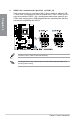
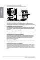
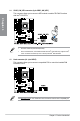
• SystempowerLED(2-pinor3-1pinPLED)
The2-pinor3-1pinconnectorisforthesystempowerLED.Connectthechassis
powerLEDcabletothisconnector.ThesystempowerLEDlightsupwhenyouturnon
thesystempower,andblinkswhenthesystemisinsleepmode.
• HarddiskdriveactivityLED(2-pinHDD_LED)
This2-pinconnectorisfortheHDDActivityLED.ConnecttheHDDActivityLEDcable
tothisconnector.TheHDDLEDlightsuporasheswhendataisreadfromorwritten
totheHDD.
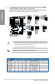
• Systemwarningspeaker(4-pinSPEAKER)
This4-pinconnectorisforthechassis-mountedsystemwarningspeaker.Thespeaker
allowsyoutohearsystembeepsandwarnings.
• ATXpowerbutton/soft-offbutton(2-pinPWRSW)
Thisconnectorisforthesystempowerbutton.Pressingthepowerbuttonturnsthe
systemonorputsthesysteminsleeporsoft-offmodedependingontheoperating
systemsettings.Pressingthepowerswitchformorethanfoursecondswhilethe
systemisONturnsthesystemOFF.
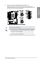
• Resetbutton(2-pinRESET)
This2-pinconnectorisforthechassis-mountedresetbuttonforsystemrebootwithout
turningoffthesystempower.
• Chassisintrusionconnector(2-pinCHASSIS)
Thisconnectorisforachassis-mountedintrusiondetectionsensororswitch.Connect
oneendofthechassisintrusionsensororswitchcabletothisconnector.Thechassis
intrusionsensororswitchsendsahigh-levelsignaltothisconnectorwhenachassis
componentisremovedorreplaced.Thesignalisthengeneratedasachassisintrusion
event.
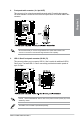
9. System panel connector (20-3 pin PANEL)
Thisconnectorsupportsseveralchassis-mountedfunctions.