
User Manual


1-2
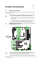
Chapter 1: Product introduction
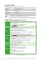
1.2.1 Layout contents
Connectors / Jumpers / Slots / LED
Page
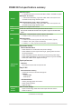
1.
ATXpowerconnectors(24-pinEATXPWR,8-pinEATX12V) 1-2
2.
CPUandchassisfanconnectors(4-pinCPU_FAN,4-pinCHA_FAN1/2) 1-2
3. FanRGBheader(4-pinFAN_RGB_HEADER) 1-3
4. M.2 Socket 3 1-3
5. AMDAM4CPUsocket 1-3
6. DDR4DIMMslots 1-4
7. AMDX370SATA6.0Gb/sports(SATA6G_1~6) 1-4
8. Systempanelconnector(20-5pinPANEL) 1-4
9. USB3.1Gen1connector(20-1pinUSB3_12) 1-4
10. USB2.0connectors(10-1pinUSB3~6) 1-5
11. Serialportconnector(10-1pinCOM) 1-5
12. Digitalaudioconnector(4-1pinSPDIF_OUT) 1-5
13. Frontpanelaudioconnector(10-1pinAAFP) 1-5
14. ClearRTCRAM(2-pinCLRTC) 1-6
15. PCIExpress2.0x1slots 1-6
16. PCIslots 1-6
17. PCIExpressx16slots 1-6
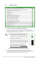
1. ATX power connectors (24-pin EATXPWR, 8-pin EATX12V)
TheseconnectorsareforATXpowersupplyplugs.Thepowersupplyplugsare
designedtottheseconnectorsinonlyoneorientation.Findtheproperorientationand
pushdownrmlyuntiltheconnectorscompletelyt.
•
WerecommendthatyouuseanEATX12VSpecication
2.0-compliantpowersupplyunit(PSU)withaminimumof300W
powerrating.ThisPSUtypehas24-pinand8-pinpowerplugs.
•
DONOTforgettoconnectthe4-pin/8-pinATX+12Vpowerplug.
Otherwise,thesystemwillnotbootup.
• WerecommendthatyouuseaPSUwithhigherpoweroutput
whenconguringasystemwithmorepower-consumingdevices
orwhenyouintendtoinstalladditionaldevices.Thesystemmay
become unstable or may not boot up if the power is inadequate.
•
Ifyouareuncertainabouttheminimumpowersupply
requirementforyoursystem,refertotheRecommended
PowerSupplyWattageCalculatorathttp://support.asus.com/
PowerSupplyCalculator/PSCalculator.aspx?SLanguage=en-us for
details.
EATX12V
+12V DC
+12V DC
+12V DC
+12V DC
GND
GND
GND
GND
EATXPWR
PIN 1
PIN 1
GND
+5 Volts
+5 Volts
+5 Volts
-5 Volts
GND
GND
GND
PSON#
GND
-12 Volts
+3 Volts
+3 Volts
+12 Volts
+12 Volts
+5V Standby
Power OK
GND
+5 Volts
GND
+5 Volts
GND
+3 Volts
+3 Volts
2. CPU and chassis fan connectors (4-pin CPU_FAN, 4-pin CHA_FAN1/2)
Connectthefancablestothefanconnectorsonthemotherboard,ensuringthatthe
black wire of each cable matches the ground pin of the connector.