Motherboard Pro WS TRX50-SAGE WIFI
E23017 Revised Edition V2 December 2023 Copyright © 2023 ASUSTeK COMPUTER INC. All Rights Reserved. No part of this manual, including the products and software described in it, may be reproduced, transmitted, transcribed, stored in a retrieval system, or translated into any language in any form or by any means, except documentation kept by the purchaser for backup purposes, without the express written permission of ASUSTeK COMPUTER INC. (“ASUS”).
Contents Safety information....................................................................................................... iv About this guide........................................................................................................... v Pro WS TRX50-SAGE WIFI specifications summary............................................. viii Package contents.......................................................................................................
Safety information Electrical safety • To prevent electrical shock hazard, disconnect the power cable from the electrical outlet before relocating the system. • When adding or removing devices to or from the system, ensure that the power cables for the devices are unplugged before the signal cables are connected. If possible, disconnect all power cables from the existing system before you add a device.
About this guide This user guide contains the information you need when installing and configuring the motherboard. How this guide is organized This guide contains the following parts: • Chapter 1: Product Introduction This chapter describes the features of the motherboard and includes descriptions for each part of the motherboard. • Chapter 2: Basic Setup This chapter lists the basic setup procedures for setting up your motherboard.
4. Motherboard Installation Guide Please visit https://www.asus.com/support for more information on the Motherboard Installation Guide. 5. Driver and Utilities FAQ Please visit https://www.asus.com/support for more information on downloading and installing drivers and utilities for your motherboard. 6. RAID Configuration Guide Please visit https://www.asus.com/support for more information on the RAID Configuration Guide. Please visit the AMD website for the latest information on RAID configurations.
Conventions used in this guide To ensure that you perform certain tasks properly, take note of the following symbols used throughout this user guide. CAUTION: Information to prevent damage to the components and injuries to yourself when trying to complete a task. IMPORTANT: Instructions that you MUST follow to complete a task. NOTE: Tips and additional information to help you complete a task.
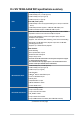
Pro WS TRX50-SAGE WIFI specifications summary CPU AMD Socket sTR5 for Ryzen™ Threadripper™ PRO 7000 WX-Series and Ryzen™ Threadripper™ 7000 Series Processors* Chipset AMD TRX50 Chipset * Refer to www.asus.com for CPU support list.
Pro WS TRX50-SAGE WIFI specifications summary Rear USB (Total 9 ports) 1 x USB 20Gbps port (1 x USB Type-C®) 6 x USB 10Gbps ports (6 x Type-A) 2 x USB 2.0 ports (2 x Type-A) USB Front USB (Total 7 ports) 1 x USB 20Gbps connector (supports USB Type-C® with up to 27W PD/ QC4+) 1 x USB 5Gbps header supports 2 additional USB 5Gbps ports 2 x USB 2.0 headers support 4 additional USB 2.
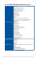
Pro WS TRX50-SAGE WIFI specifications summary Power related 2 x 24-pin Main Power connectors 2 x 8-pin +12V Power connectors 2 x 8-pin PCIe to CPU power connectors 1 x 6-pin PCIe Power connector 1 x 8-pin PCIe Power connector Storage related 3 x M.2 slots (Key M) 4 x SATA 6Gb/s ports 1 x SlimSAS port USB 1 x USB 20Gbps connector supports USB Type-C® 1 x USB 5Gbps header supports 2 additional USB 5Gbps ports 2 x USB 2.0 headers support 4 additional USB 2.
Pro WS TRX50-SAGE WIFI specifications summary ASUS EZ DIY - BIOS FlashBack™ button - BIOS FlashBack™ LED - Clear CMOS button - ProCool II Special Features - Pre-mounted I/O shield - SafeSlot - SafeDIMM Bespoke Motherboard Design & Business Focused Features - 24/7 Reliability - Overcurrent Protection ASUS Exclusive Software Armoury Crate - Fan Xpert 4 ASUS CPU-Z IT Management software supported - ASUS Control Center Express(ACCE) Software Features Adobe Creative Cloud (Free Trial) Norton 360 Deluxe (60 Da
Package contents Check your motherboard package for the following items. Motherboard Pro WS TRX50-SAGE WIFI motherboard 2 x SATA 6Gb/s cables Cables 1 x Thermistor cable pack 1 x CPU 8-pin to PCIe 8-pin adapter cable package 1 x ASUS WiFi Q-Antenna Miscellaneous 1 x M.2 Q-Latch package(2 in 1) 2 x M.2 Rubber Packages 1 x Q-connector Documentation xii 1 x ACC Express Activation Key Card 1 x Quick start guide • If any of the above items is damaged or missing, contact your retailer.
Product Introduction Product Introduction 1.1 Before you proceed 1 Chapter 1 Chapter 1: Take note of the following precautions before you install motherboard components or change any motherboard settings. • Unplug the power cord from the wall socket before touching any component. • Before handling components, use a grounded wrist strap or touch a safely grounded object or a metal object, such as the power supply case, to avoid damaging them due to static electricity.
1.
Motherboard User Manual Page 1-4 1-5 1-6 1-8 1-8 1-9 1-9 1-10 1-10 1-10 1-11 1-11 1-11 1-12 1-12 1-12 1-12 1-13 1-13 1-14 1-15 1-15 1-15 1-15 1-16 1-16 1-16 1-17 1-17 1-17 1-18 1-18 Chapter 1 Layout contents 1. CPU socket 2. DIMM slots 3. Expansion slots 4. Fan and Pump headers 5. VRM Heatsink Fan header 6. Power connectors 7. M.2 slot 8. SATA 6Gb/s port 9. SlimSAS port 10. USB4® header 11. USB 20Gbps Type-C® Front Panel connector 12. USB 5Gbps header 13. USB 2.0 header 14. BMC header 15.
1. CPU socket The motherboard comes with a Socket sTR5 for AMD Ryzen™ Threadripper™ PRO 7000 WX-Series and Ryzen™ Threadripper™ 7000 Series Processors. Chapter 1 Socket sTR5 1-4 • The Socket sTR5 has a different pinout design. Ensure that you use a CPU designed for the Socket sTR5 socket. • The CPU fits in only one correct orientation. DO NOT force the CPU into the socket to prevent bending the connectors on the socket and damaging the CPU.
2. DIMM slots Chapter 1 The motherboard comes with Dual Inline Memory Modules (DIMM) slots designed for DDR5 (Double Data Rate 5) memory modules. A DDR5 memory module is notched differently from a DDR, DDR2, DDR3, or DDR4 module. DO NOT install a DDR, DDR2, DDR3, or DDR4 memory module to the DDR5 slot. Recommended memory configurations Slot 1-DIMM 2-DIMM 4-DIMM A1 V V V C1 E1 G1 V V V V Memory configurations You may install ECC registered DDR5 DIMMs into the DIMM sockets.
3. Expansion slots Unplug the power cord before adding or removing expansion cards. Failure to do so may cause you physical injury and damage motherboard components. Chapter 1 To install a PCIe expansion card, please refer to the Motherboard Installation Guide on the ASUS support site. Please refer to the following tables for the recommended VGA configuration and PCIe bifurcation configuration.
Recommended VGA configuration Single VGA V Dual VGA V V 3-way VGA V V V 4-way VGA V V V V Chapter 1 Slot Description 1 PCIEX16(G5)_1 2 PCIEX16(G5)_2 3 PCIEX16(G5)_3 5 PCIEX16(G4)_2 Connect a chassis fan to the chassis fan connectors when using multiple graphics cards for better thermal environment. When installing a dual VGA card, we recommend selecting a chassis case which supports 7 or more expansion slots PCIe bifurcation & M.
4. Fan and Pump headers The Fan and Pump headers allow you to connect fans or pumps to cool the system. Chapter 1 CPU_FAN CHA_FAN3 CPU_OPT CHA_FAN4 CHA_FAN1 W_PUMP+ CHA_FAN2 5. • DO NOT forget to connect the fan cables to the fan headers. Insufficient air flow inside the system may damage the motherboard components. These are not jumpers! Do not place jumper caps on the fan headers! • Ensure the cable is fully inserted into the header.
6. Power connectors Chapter 1 These Power connectors allow you to connect your motherboard to a power supply. The power supply plugs are designed to fit in only one orientation, find the proper orientation and push down firmly until the power supply plugs are fully inserted.
8. SATA 6Gb/s connector The SATA 6Gb/s connector allows you to connect SATA devices such as optical disc drives and hard disk drives via a SATA cable. Chapter 1 SATA6G_1 SATA6G_2 SATA6G_3 SATA6G_4 9. • If you installed SATA storage devices to the SATA6G_1-4 ports, you can create a RAID 0, 1, and 10 configuration through the onboard AMD TRX50 chipset. • AMD RAIDXpert2 Technology supports both PCIe RAID 0/1/5/10 and SATA RAID 0/1/5/10.
11. USB 20Gbps Type-C® Front Panel connector Chapter 1 The USB 20Gbps Type-C® connector allows you to connect a USB 20Gbps Type-C® module for additional USB 20Gbps ports on the front panel. U20G_C5 12. USB 5Gbps header The USB 5Gbps header allows you to connect a USB 5Gbps module for additional USB 5Gbps ports. The USB 5Gbps header provides data transfer speeds of up to 5 Gb/s. U5G_910 13. USB 2.0 header The USB 2.0 header allows you to connect a USB module for additional USB 2.0 ports. The USB 2.
14. BMC header The BMC header allows you to connect and support an IPMI card. Chapter 1 BMC_HEADER For more information on the installation and information regarding the IPMI card, please visit www.asus.com. 15. Chassis Intrusion header The Chassis Intrusion header allows you to connect a intrusion sensor or microswitch for the chassis intrusion detection feature.
18. Front Panel Audio header Chapter 1 The Front Panel Audio header is for a chassis-mounted front panel audio I/O module that supports HD Audio. Connect one end of the front panel audio I/O module cable to this header. F_AUDIO 19. LN2 Mode jumper Set to pins 2-3 to optimize the motherboard to remedy the cold-boot bug during POST and help the system boot successfully.
20. ProbeIt Measurement Points The ProbeIt allows you to detect your system’s current voltage and OC settings using a multimeter. You can also measure the ProbeIt points during overclocking. Chapter 1 ProbeIt Using ProbeIt Connect one of the probes onto the GND point on the motherboard. The GND point is the screw hole located in the illustration below: Then connect the other probe onto another ProbeIt point to measure the corresponding voltage information.
21. ReTry button Chapter 1 The ReTry button is specially designed for overclockers and is most useful during the booting process where the Reset button is rendered useless. Press this button to force the system to reboot while retaining the same settings to be retried in quick succession to achieve a successful POST. RETRY_BUTTON 22. RSVD switch The RSVD switch is reserved for ASUS-authorized technicians only. RSVD Please ensure the RSVD switch is set to Disabled.
25. Start button Press the Power button to power up the system, or put the system into sleep or softoff mode (depending on the operating system settings). Chapter 1 START 26. System Panel header The System Panel header supports several chassis-mounted functions. F_PANEL • System Power LED header (PLED) The 2-pin header allows you to connect the System Power LED.
28. TPM header Chapter 1 The TPM header allows you to connect a TPM module, which securely stores keys, digital certificates, passwords, and data. A TPM system also helps enhance network security, protect digital identities, and ensures platform integrity. TPM1 29. Q-Code LED The Q-Code LED design provides you with a 2-digit error code that displays the system status. Q_CODE • The Q-Code LEDs provide the most probable cause of an error code as a starting point for troubleshooting.
31. 8-pin PCIe Power Plug LED The 8-pin PCIe Power Plug LED lights up to indicate if the 8-pin power plug PCIE_8P(1)_PWR is not connected. Chapter 1 PLUG_8PIN_PCIE 32. 8-pin Power Plug LED The 8-pin Power Plug LED lights up to indicate that the 8-pin power plug is not connected.
Motherboard rear and audio connections 1.3.1 Rear I/O connection Chapter 1 1.3 Rear panel connectors 2. 3. 4. 5. 6. 7. 8. 9. 10. Clear CMOS button (CLR_CMOS). Press this button to clear the BIOS setup information only when the systems hangs due to overclocking. Intel® 2.5Gb Ethernet port* Marvell® AQtion 10Gb Ethernet port* USB 2.
* Intel® 2.5Gb Ethernet port LED indications Chapter 1 Activity Link LED Status Description OFF No link GREEN Linked BLINKING Data activity Speed LED Status Description OFF No link 100 Mbps / 10 Mbps OFF connection GREEN 2.5 Gbps connection ORANGE 1 Gbps connection ACT/LINK LED SPEED LED LAN port * Marvell® AQtion 10Gb Ethernet port LED indications Activity Link LED Status Description OFF No link GREEN Linked BLINKING Data activity Speed LED Status Description OFF No link GREEN 10 Gbps 5 Gbps/ 2.
Chapter 1 Connect to Headphone and Mic Connect to 2-channel Speakers Connect to 4-channel Speakers Motherboard User Manual 1-21
Connect to 5.
Chapter 2: Basic Setup Basic Setup 2 The installation diagrams in this section are for reference only. The motherboard layout may vary with models, but the installation steps are the same for all models. CPU installation • Ensure that you use a CPU designed for the Socket sTR5 socket. The CPU fits in only one correct orientation. DO NOT force the CPU into the socket to prevent bending the pins and damaging the CPU • The CPU fits in only one correct orientation.
Chapter 2 2-2 Chapter 2: Basic Installation
DIMM installation Chapter 2 2.
2.3 M.2 module installation • The illustrations only show the installation steps for a 22110 M.2 slot, the steps are the same for the other M.2 slots. • Use a Phillips screwdriver when removing or installing the screws or screw stands mentioned in this section. • If the thermal pad on the M.2 heatsink becomes damaged, we recommend replacing it with the bundled thermal pad or a thermal pad with a thickness of 1.25mm. • Supported M.2 type varies per motherboard. 1. Loosen the screws from the M.
3. Install your M.2 to your M.2 slot. The steps may differ between the different M.2 slots, please refer to the different installation steps below: M.2_1(Socket3) and M.2_2(Socket3) slots A. Peel the plastic film off the M.2 slot you wish to install an M.2 module to. M.2_PAD B. (optional) If required, remove the pre-installed removable M.2 Q-Latch screw at the 2280 length screw hole. Chapter 2 Only follow this step if a removable M.
D. (optional) If you are installing an 2280 or 22110 single sided M.2 storage device, ensure to peel off the plastic film on the bundled rubber for M.2, then stick them in the rubber for M.2 location. DO NOT install the bundled rubber for M.2 when installing a double-sided M.2 storage device. M.2_PAD Chapter 2 OPTIONAL M.2 _P AD E. (optional) Install the M.2 Q-Latch to the M.2 length screw hole you wish to install your M.2 module to. You can use a bundled M.2 Q-Latch or a pre-installed removable M.
G. Install your M.2 module to the M.2 slot. Ensure that there is nothing obstructing your M.2 module when installing the M.2 module to the M.2 slot. H. Rotate the M.2 Q-Latch clockwise to secure the M.2 module in place. M.2_PAD M.2_3(Socket3) slot Chapter 2 A. (optional) Install the bundled rubber for M.2 if you are installing a single sided M.2 module. DO NOT install the bundled rubber for M.2 when installing a double-sided M.2 module.
C. Install your M.2 module to the M.2 slot. Ensure that there is nothing obstructing your M.2 module when installing the M.2 module to the M.2 slot. D. Rotate the M.2 Q-Latch clockwise to secure the M.2 module in place. 4. Remove the plastic film from the thermal pads on the bottom of the heatsinks. Chapter 2 If the thermal pad on the M.2 heatsink becomes damaged, we recommend replacing it with the bundled thermal pad or a thermal pad with a thickness of 1.25mm. 5. Replace the heatsinks. 6.
2.4 1. Motherboard installation (on selected models) Install the bundled I/O Shield to the chassis rear I/O panel. 2. Place the motherboard into the chassis, ensuring that its rear I/O ports are aligned to the chassis’ rear I/O panel. 3. Place nine (9) screws into the holes indicated by circles to secure the motherboard to the chassis. Chapter 2 Only install the I/O Shield if your motherboard does not have a pre-installed I/O shield.
2.5 Power connection To avoid damages, please refer to the following configurations when installing the PSU(s). Single PSU installation ATX_PWR(1) CPU_12V(1)_1 CPU_12V(2)_1 PCIE_8P(1)_PWR PCIE_6P(1)_PWR Chapter 2 When the system is powered by only one (1) PSU, ensure to use a single rail PSU if you wish to connect PCIE 8-pin connectors to PCIE_CPU_12V_1 and PCIE_CPU_12V_2.
2.6 ASUS WiFi Q-Antenna installation Installing the ASUS WiFi Q-Antenna Chapter 2 Connect the bundled ASUS WiFi Q-Antenna connector to the Wi-Fi ports at the back of the chassis. • Ensure to hold tightly onto the connector when removing the antenna connector from the Wi-Fi ports, and refrain from attempting to remove the antenna connector from the Wi-Fi ports by pulling on the antenna connector cable. • The antenna can only be extended to a right angle (90°).
2.7 BIOS FlashBack™ The illustrations for this section are for reference only. The WiFi module is only available on selected models. BIOS FlashBack™ allows you to easily update the BIOS without entering the existing BIOS or operating system. To use BIOS FlashBack™: 1. Visit https://www.asus.com/support/ and download the latest BIOS version for this motherboard. 2. Launch the BIOSRenamer.
2.8 Starting up for the first time 1. After making all the connections, replace the system case cover. 2. Ensure that all switches are off. 3. Connect the power cord to the power connector at the back of the system chassis. 4. Connect the power cord to a power outlet that is equipped with a surge protector. 5. Turn on the devices in the following order: Monitor b. External storage devices (starting with the last device on the chain) c.
Chapter 2 2-14 Chapter 2: Basic Installation
Chapter 3: BIOS and RAID Support BIOS and RAID Support 3.1 3 • For more details on BIOS and RAID configurations, please refer to Manual & Document under the Support tab of the product information site, or visit https://www.asus.com/support. • Please visit the AMD website for the latest information on RAID configurations.
3.2 ASUS EZ Flash Utility The ASUS EZ Flash Utility feature allows you to update the BIOS without using an OS‑based utility. Ensure to load the BIOS default settings to ensure system compatibility and stability. Select the Load Optimized Defaults item under the Exit menu or press hotkey . To update the BIOS: • This function can support devices such as a USB flash disk with FAT 32/16 format and single partition only.
3.3 ASUS CrashFree BIOS 3 The ASUS CrashFree BIOS 3 utility is an auto recovery tool that allows you to restore the BIOS file when it fails or gets corrupted during the updating process. You can restore a corrupted BIOS file using a USB flash drive that contains the BIOS file. Recovering the BIOS 1. Download the latest BIOS version for this motherboard from https://www.asus.com/support/. 2. Rename the file using one of the following methods: • Launch the BIOSRenamer.
3.4 RAID configurations The motherboard supports RAID configurations. RAID definitions Volume provides the ability to link-together storage from one or several disks, regardless of the size of the space on those disks. This configuration is useful in scavenging space on disks unused by other disks in the array. This configuration does not provide performance benefits or data redundancy, disk failure will result in data loss.
Appendix Appendix Appendix Pro WS TRX50-SAGE WIFI block diagram Motherboard User Manual A-1
General Notices FCC Compliance Information Responsible Party: Asus Computer International Address: 48720 Kato Rd., Fremont, CA 94538, USA Phone / Fax No: (510)739-3777 / (510)608-4555 This device complies with part 15 of the FCC Rules. Operation is subject to the following two conditions: (1) This device may not cause harmful interference, and (2) this device must accept any interference received, including interference that may cause undesired operation.
VCCI: Japan Compliance Statement Class B ITE Japan JATE 本製品は電気通信事業者(移動通信会社、固定通信会社、インターネットプロバイダ等)の通信 回線(公衆無線LANを含む)に直接接続することができません。本製品をインターネットに接続す る場合は、必ずルーター等を経由し接続してください。 Declaration of compliance for product environmental regulation ASUS follows the green design concept to design and manufacture our products, and makes sure that each stage of the product life cycle of ASUS product is in line with global environmental regulations.
Türkiye RoHS AEEE Yönetmeliğine Uygundur ASUS Recycling/Takeback Services ASUS recycling and takeback programs come from our commitment to the highest standards for protecting our environment. We believe in providing solutions for you to be able to responsibly recycle our products, batteries, other components as well as the packaging materials. Please go to http://csr.asus.com/english/Takeback.htm for detailed recycling information in different regions. DO NOT throw the motherboard in municipal waste.
Notices for Wi-Fi model FCC RF Caution Statement WARNING: Any changes or modifications not expressly approved by the party responsible for compliance could void your authority to operate the equipment. FCC Wi-Fi Caution Statement Operation of transmitters in the 5.925-7.125 GHz band is prohibited for control of or communications with unmanned aircraft systems.
KC: Korea Warning Statement NCC: Wireless Statement 取得審驗證明之低功率射頻器材,非經核准,公司、商號或使用者均不得擅自變更頻 率、加大功率或變更原設計之特性及功能。低功率射頻器材之使用不得影響飛航安全及 干擾合法通信;經發現有干擾現象時,應 立即停用,並改善至無干擾時方得繼續使用。 前述合法通信,指依電信管理法規定作業之無線電通信。低功率射頻器材須忍受合法通 信或工業、科學及醫療用電波輻射性電機設備之干擾。 應避免影響附近雷達系統之操作。 Japan RF Equipment Statement 屋外での使用について 5GHz帯(W52/53)及び6GHz帯(LPI)の屋外での使用は、電波法により禁じられています(法令に より許可された場合は除く) (6GHz帯は対応製品のみ)。 法律および規制遵守 本製品は電波法及びこれに基づく命令の定めるところに従い使用してください。日本国外では、 その国の法律または規制により、本製品の使用ができないことがあります。このような国では、本 製品を運用した結果、罰せられることがありますが、当社は一切責任を負いかねますの
Simplified UKCA Declaration of Conformity ASUSTek Computer Inc. hereby declares that this device is in compliance with the essential requirements and other relevant provisions of The Radio Equipment Regulations 2017 (S.I. 2017/1206). Full text of UKCA declaration of conformity is available at https://www.asus.com/support/.
Appendix Simplified EU Declaration of Conformity ASUSTek Computer Inc. hereby declares that this device is in compliance with the essential requirements and other relevant provisions of Directive 2014/53/EU. Full text of EU declaration of conformity is available at https://www.asus.com/support/. The WiFi operating in the band 5150-5350MHz shall be restricted to indoor use for countries listed in the table below: a.
Motherboard User Manual Lihtsustatud EÜ vastavusdeklaratsioon Käesolevaga kinnitab ASUSTek Computer Inc, et seade vastab direktiivi 2014/53/EÜ olulistele nõuetele ja teistele asjakohastele sätetele. EL vastavusdeklaratsiooni täistekst on saadaval veebisaidil https://www.asus.com/support/. Sagedusvahemikus 5150-5350 MHz töötava WiFi kasutamine on järgmistes riikides lubatud ainult siseruumides: a.
הצהרת תאימות רגולטורית מקוצרת עבור האיחוד אירופי מצהירה בזאת כי מכשיר זה תואם לדרישותASUSTek Computer Inc. ניתן לקרוא את.2014/53/EU החיוניות ולשאר הסעיפים הרלוונטיים של תקנה :הנוסח המלא של הצהרת התאימות הרגולטורית עבור האיחוד האירופי בכתובת .https://www.asus.com/support/ לשימוש5150-5350MHz הפועלות ברצועת התדריםWi-Fi יש להגביל רשתות :בתוך מבנים סגורים בארצות המפורטות ברשימה הבאה :)LPI( לבית בהספק נמוךWi-Fi מכשיריa.
Motherboard User Manual Por la presente, ASUSTek Computer Inc. declara que este dispositivo cumple los requisitos básicos y otras disposiciones pertinentes de la directiva 2014/53/EU. En https://www.asus.com/support/ está disponible el texto completo de la declaración de conformidad para la UE. La conexión WiFi con una frecuencia de funcionamiento de 5150-5350 MHz se restringirá al uso en interiores para los países enumerados en la tabla: a.
ASUSTek Computer Inc. заявляє, що цей пристрій відповідає основним вимогам та іншим відповідним вимогам Директиви 2014 / 53 / EU. Повний текст декларації відповідності нормам ЄС доступний на https://www.asus.com/support/. Робота Wi-Fi на частоті 5150-5350 МГц обмежується використанням у приміщенні для країн, поданих у таблиці нижче: a. b.
Warranty EN: ASUS Guarantee Information • ASUS offers a voluntary manufacturer’s Commercial Guarantee. • ASUS reserves the right to interpret the provisions of the ASUS Commercial Guarantee. • This ASUS Commercial Guarantee is provided independently and in addition to the statutory Legal Guarantee and in no way affects or limits the rights under the Legal Guarantee. CR: Informacije o ASUS jamstvu • ASUS dragovoljno nudi komercijalno proizvođačko jamstvo.
Appendix PG: Informações de Garantia ASUS • A ASUS oferece uma Garantia Comercial voluntária do fabricante. • A ASUS reserva o direito de interpretar as disposições da Garantia Comercial da ASUS. • Esta Garantia Comercial da ASUS é fornecida de forma independente além da Garantia Legal estatutária e não afeta nem limita de qualquer forma os direitos estabelecidos na Garantia Legal. Para consultar todas as informações sobre a garantia, visite https://www.asus.com/pt/support/.
ASUS contact information ASUSTeK COMPUTER INC. Address: 1F., No. 15, Lide Rd., Beitou Dist., Taipei City 112 ASUS COMPUTER INTERNATIONAL (America) Address: 48720 Kato Rd., Fremont, CA 94538, USA ASUS COMPUTER GmbH (Germany and Austria) Address: Harkortstrasse 21-23, 40880 Ratingen, Germany ASUSTeK (UK) LIMITED Address: 1st Floor, Sackville House, 143-149 Fenchurch Street, London, EC3M 6BL, England, United Kingdom Service and Support Visit our multi-language website at https://www.asus.com/support.
Appendix A-16 Appendix