Motherboard ProArt B650CREATOR
E20611 First Edition October 2022 Copyright © 2022 ASUSTeK COMPUTER INC. All Rights Reserved. No part of this manual, including the products and software described in it, may be reproduced, transmitted, transcribed, stored in a retrieval system, or translated into any language in any form or by any means, except documentation kept by the purchaser for backup purposes, without the express written permission of ASUSTeK COMPUTER INC. (“ASUS”).
Contents Safety information........................................................................................................ v About this guide.......................................................................................................... vi ProArt B650-CREATOR specifications summary.................................................... vii Package contents.......................................................................................................
Appendix Notices ..................................................................................................................... A-1 Warranty.................................................................................................................... A-6 ASUS contact information....................................................................................... A-8 Service and Support................................................................................................
Safety information Electrical safety • To prevent electrical shock hazard, disconnect the power cable from the electrical outlet before relocating the system. • When adding or removing devices to or from the system, ensure that the power cables for the devices are unplugged before the signal cables are connected. If possible, disconnect all power cables from the existing system before you add a device.
About this guide This user guide contains the information you need when installing and configuring the motherboard. How this guide is organized This guide contains the following parts: • Chapter 1: Product Introduction This chapter describes the features of the motherboard and the new technology it supports. It includes description of the switches, jumpers, and connectors on the motherboard.
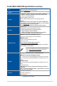
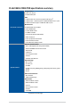
ProArt B650-CREATOR specifications summary CPU Chipset AMD Socket AM5 for AMD Ryzen™ 7000 Series Desktop Processors* * Refer to www.asus.com for CPU support list. AMD B650 4 x DIMM, Max.
ProArt B650-CREATOR specifications summary Wireless & Bluetooth® M.2 slot only (Key E, PCIe)* * Wi-Fi module is sold separately. Rear USB (Total 7 ports) 1 x USB 3.2 Gen 2 port (1 x USB Type-C®, shared with DisplayPort graphic output) 4 x USB 3.2 Gen 2 ports (3 x Type-A + 1 x USB Type-C®) USB 2 x USB 2.0 ports (2 x Type-A) Front USB (Total 7 ports) 1 x USB 3.2 Gen 2x2 connector (supports USB Type-C® with up to 60W PD/QC4+) 1 x USB 3.2 Gen 1 header supports 2 additional USB 3.2 Gen 1 ports 2 x USB 2.
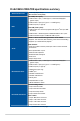
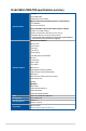
ProArt B650-CREATOR specifications summary Storage related 3 x M.2 slots (Key M) 4 x SATA 6Gb/s ports USB 1 x USB 3.2 Gen 2x2 connector (supports USB Type-C®) 1 x USB 3.2 Gen 1 header supports 2 additional USB 3.2 Gen 1 ports 2 x USB 2.0 headers support 4 additional USB 2.0 ports Miscellaneous Internal I/O connectors 3 x Addressable Gen 2 headers 1 x Aura RGB header 1 x Clear CMOS header 1 x COM Port header 1 x Front Panel Audio header (AAFP) 1 x M.
ProArt B650-CREATOR specifications summary Aura Sync - Aura RGB header - Addressable Gen 2 headers Bespoke Motherboard Design & Business Focused Features - 24/7 Reliability Special Features - Overcurrent Protection Front Panel USB 3.2 Gen 2x2 with Quick Charge 4+ Support - Support: up to 60W charging* - Output: 5/9/15/20V max. 3A, PPS:3.3–21V max. 3A - Compatible with QC 4.0/3.0/2.0, PD3.
• Specifications are subject to change without notice. Please refer to the ASUS website for the latest specifications.
Package contents Check your motherboard package for the following items. Motherboard Cables 1 x ProArt B650-CREATOR motherboard 1 x DisplayPort cable 2 x SATA 6Gb/s cables 1 x Q-connector 1 x Rubber Package for M.2 Miscellaneous 1 x Screw package for M.2 SSD 1 x Screw package for M.2 Key E Documentation 1 x ProArt ruler 1 x ACC Express Activation Key Card 1 x User guide If any of the above items is damaged or missing, contact your retailer.
Connectors with shared bandwidth A A B B Configuration A 1 (Default) 2 PCIEX16_1 x16 x8 PCIEX16_2 - x8 1 (Default) 2 x4 - - x4 Configuration B M.
xiv
Product Introduction Product Introduction 1.1 Before you proceed 1 Chapter 1 Chapter 1: Take note of the following precautions before you install motherboard components or change any motherboard settings. • Unplug the power cord from the wall socket before touching any component. • Before handling components, use a grounded wrist strap or touch a safely grounded object or a metal object, such as the power supply case, to avoid damaging them due to static electricity.
1.
ProArt B650-CREATOR Page 1-4 1-5 1-7 1-9 1-10 1-11 1-12 1-13 1-14 1-15 1-16 1-17 1-18 1-19 1-20 1-20 1-21 1-22 1-23 1-24 1-24 1-25 Chapter 1 Layout contents 1. CPU socket 2. DIMM slots 3. Expansion slots 4. Fan and Pump headers 5. Power connectors 6. M.2 Slot 7. SATA 6Gb/s port 8. USB 3.2 Gen 2x2 Type-C® Front Panel connector 9. USB 3.2 Gen 1 header 10. USB 2.0 header 11. Addressable Gen 2 header 12. Aura RGB header 13. Clear CMOS header 14. COM Port header 15. Front Panel Audio header 16. M.
1. CPU socket The motherboard comes with a Socket AM5 designed for AMD Ryzen™ 7000 Series Desktop Processors. Chapter 1 1-4 • The AM5 socket has a different pinout design. Ensure that you use a CPU designed for the AM5 socket. • The CPU fits in only one correct orientation. DO NOT force the CPU into the socket to prevent bending the connectors on the socket and damaging the CPU. • Ensure that all power cables are unplugged before installing the CPU.
2. DIMM slots The motherboard comes with Dual Inline Memory Modules (DIMM) slots designed for DDR5 (Double Data Rate 5) memory modules. Chapter 1 A DDR5 memory module is notched differently from a DDR, DDR2, DDR3, or DDR4 module. DO NOT install a DDR, DDR2, DDR3, or DDR4 memory module to the DDR5 slot.
Memory configurations You may install 8GB, 16GB, and 32GB unbuffered, ECC or non‑ECC DDR5 DIMMs into the DIMM sockets. Chapter 1 You may install varying memory sizes in Channel A and Channel B. The system maps the total size of the lower-sized channel for the dual-channel configuration. Any excess memory from the higher-sized channel is then mapped for single-channel operation.
3. Expansion slots Chapter 1 Unplug the power cord before adding or removing expansion cards. Failure to do so may cause you physical injury and damage motherboard components. • Additional PCIe bifurcation and M.2 settings for RAID function are also supported when a Hyper M.2 x16 series card is installed. • For full details on the PCIe bifurcation, you may visit the support site at https://www.asus.com/support/FAQ/1037507/. • The Hyper M.2 x16 series card is sold separately.
Recommended VGA configuration Chapter 1 Slot Description 1 PCIEX16_1 2 PCIEX16_2 Single VGA x16 Dual VGA x8 - x8 Connect a chassis fan to the chassis fan connectors when using multiple graphics cards for better thermal environment.
4. Fan and Pump headers Chapter 1 The Fan and Pump headers allow you to connect fans or pumps to cool the system. • DO NOT forget to connect the fan cables to the fan headers. Insufficient air flow inside the system may damage the motherboard components. These are not jumpers! Do not place jumper caps on the fan headers! • Ensure the cable is fully inserted into the header. For water cooling kits, connect the pump connector to the AIO_PUMP header.
5. Power connectors These Power connectors allow you to connect your motherboard to a power supply. The power supply plugs are designed to fit in only one orientation, find the proper orientation and push down firmly until the power supply plugs are fully inserted. Chapter 1 Ensure to connect the 8-pin power plug, or connect both the 8-pin and 4-pin power plugs. • We recommend that you use a PSU with a higher power output when configuring a system with more power-consuming devices.
6. M.2 slot Chapter 1 The M.2 slot allows you to install M.2 devices such as M.2 SSD modules. • AMD Ryzen™ 7000 Series Desktop Processors: - M.2_1 supports PCIE 5.0 x4 mode M Key design and type 2242 / 2260 / 2280 storage devices. -M .2_2 supports PCIE 4.0 x4 mode M Key design and type 2242 / 2260 / 2280 / 22110 storage devices. • AMD B650 Chipset: - M.2_3 supports PCIE 4.0 x4 mode M Key design and type 2242 / 2260 / 2280 / 22110 storage devices. • M.2_3 slot shares bandwidth with PCIEX16_3.
7. SATA 6Gb/s port The SATA 6Gb/s port allows you to connect SATA devices such as optical disc drives and hard disk drives via a SATA cable. Chapter 1 If you installed SATA storage devices to the SATA6G_1-4 ports, you can create a RAID 0, 1, and 10 configuration through the onboard AMD B650 chipset. Before creating a RAID set, refer to the RAID Configuration Guide. You can download the RAID Configuration Guide from the ASUS website.
8. USB 3.2 Gen 2x2 Type-C® Front Panel connector • The USB 3.2 Gen 2x2 Type-C® module is purchased separately. • For PD 3.0 / QC 4+ support, ensure to connect the 6-pin PD_12V_PWR connector. • PD 3.0 up to DC 20V/3A 60W fast charging technology is only supported on CC Logic Devices. • In S5 (Soft Off State) PD 3.0 and QC 4+ only provide power delivery of up to 10W. ProArt B650-CREATOR Chapter 1 The USB 3.2 Gen 2x2 Type-C® connector allows you to connect a USB 3.
9. USB 3.2 Gen 1 header The USB 3.2 Gen 1 header allows you to connect a USB 3.2 Gen 1 module for additional USB 3.2 Gen 1 ports. The USB 3.2 Gen 1 header provides data transfer speeds of up to 5 Gb/s. Chapter 1 The USB 3.2 Gen 1 module is purchased separately.
10. USB 2.0 header Chapter 1 The USB 2.0 header allows you to connect a USB module for additional USB 2.0 ports. The USB 2.0 header provides data transfer speeds of up to 480 Mb/s connection speed. DO NOT connect a 1394 cable to the USB connectors. Doing so will damage the motherboard! The USB 2.0 module is purchased separately.
11. Addressable Gen 2 header The Addressable Gen 2 header allows you to connect individually addressable RGB WS2812B LED strips or WS2812B based LED strips. Chapter 1 The Addressable Gen 2 header supports WS2812B addressable RGB LED strips (5V/ Data/Ground), with a maximum power rating of 3A (5V), and the addressable headers on this board can handle a combined maximum of 500 LEDs.
12. Aura RGB header Chapter 1 The Aura RGB header allows you to connect RGB LED strips. The Aura RGB header supports 5050 RGB multi-color LED strips (12V/G/R/B), with a maximum power rating of 3A (12V). Before you install or remove any component, ensure that the power supply is switched off or the power cord is detached from the power supply. Failure to do so may cause severe damage to the motherboard, peripherals, or components. • Actual lighting and color will vary with LED strip.
13. Clear CMOS header The Clear CMOS header allows you to clear the Real Time Clock (RTC) RAM in the CMOS, which contains the date, time, system passwords, and system setup parameters. Chapter 1 To erase the RTC RAM: 1. Turn OFF the computer and unplug the power cord. 2. Short-circuit pin 1-2 with a metal object or jumper cap for about 5-10 seconds. 3. Plug the power cord and turn ON the computer. 4. Hold down the key during the boot process and enter BIOS setup to re-enter data.
14. COM Port connector Chapter 1 The COM (Serial) Port connector allows you to connect a COM port module. Connect the COM port module cable to this connector, then install the module to a slot opening on the system chassis. The COM port module is purchased separately.
15. Front Panel Audio header The Front Panel Audio header is for a chassis-mounted front panel audio I/O module that supports HD Audio. Connect one end of the front panel audio I/O module cable to this header. Chapter 1 We recommend that you connect a high-definition front panel audio module to this connector to avail of the motherboard’s high-definition audio capability. 16. M.2 slot (Key E) The M.2 Wi-Fi slot allows you to install an M.2 Wi-Fi module (E-key, type 2230; PCIe interface). The M.
17. System Panel header Chapter 1 The System Panel header supports several chassis-mounted functions. • System Power LED header (PLED) The 2-pin header allows you to connect the System Power LED. The System Power LED lights up when the system is connected to a power source, or when you turn on the system power, and blinks when the system is in sleep mode. • Storage Device Activity LED header (HDD_LED) The 2-pin header allows you to connect the Storage Device Activity LED.
18. Thermal Sensor header Chapter 1 The Thermal Sensor header allows you to connect a sensor to monitor the temperature of the devices and the critical components inside the motherboard. Connect the thermal sensor and place it on the device or the motherboard’s component to detect its temperature. The thermal sensor is purchased separately.
19. Thunderbolt™ header Chapter 1 The Thunderbolt™ header allows you to connect an add-on Thunderbolt™ I/O card that supports Intel®’s Thunderbolt™ Technology, allowing you to connect Thunderbolt™-enabled devices to form a daisy-chain configuration. • The add-on Thunderbolt™ I/O card and Thunderbolt™ cables are purchased separately. • Please visit the official website of your purchased Thunderbolt™ card for more details on compatibility.
20. Q-LEDs The Q-LEDs check key components (CPU, DRAM, VGA, and booting devices) during the motherboard booting process. If an error is found, the critical component’s LED stays lit up until the problem is solved. Chapter 1 The Q-LEDs provide the most probable cause of an error code as a starting point for troubleshooting. The actual cause may vary from case to case. 21. BIOS FlashBack™ LED The FlashBack™ LED lights up or blinks to indicate the status of the BIOS FlashBack™ LED.
22. 8-pin Power Plug LED Chapter 1 The 8-pin Power Plug LED lights up to indicate that the 8-pin power plug is not connected.
Chapter 1 1-26 Chapter 1: Product Introduction
Chapter 2: Basic Installation Basic Installation 2.1 Building your PC system 2 The diagrams in this section are for reference only. The motherboard layout may vary with models, but the installation steps are the same for all models. CPU installation • Ensure that you use a CPU designed for the AM5 socket. The CPU fits in only one correct orientation.
Chapter 2 2-2 Chapter 2: Basic Installation
2.1.2 Cooling system installation Apply the Thermal Interface Material to the CPU cooling system and CPU before you install the cooling system, if necessary. We recommend using AM5 compatible coolers with stock AM5 backplate to prevent potential damages to the pins in the socket.
CPU heatsink and fan assembly Type 2 Chapter 2 When using this type of CPU fan, remove the screws and the retention module only. Do not remove the plate on the bottom.
To install an AIO cooler Chapter 2 If you wish to install an AIO cooler, we recommend installing the AIO cooler after installing the motherboard into the chassis.
2.1.
2.1.4 M.2 installation Supported M.2 type varies per motherboard. • The illustrations only show the installation steps for a single M.2 slot, the steps are the same for the other M.2 slots if you wish to install an M.2 to another M.2 slot. • Use a Phillips screwdriver when removing or installing the screws or screw stands mentioned in this section. • The M.2 is purchased separately. 1. Completely loosen the screws on the heatsinks. 2. Lift and remove the heatsink.
• To install an M.2 to M.2_1 slot For 2280 length A. (optional) Install the bundled rubber for M.2 if you are installing a single sided M.2 storage device. DO NOT install the bundled rubber for M.2 when installing a double-sided M.2 storage device. The rubber installed by default is compatible with double sided M.2 storage devices. B. Rotate and adjust the M.2 Q-latch so that the handle points away from the M.2 slot. C. Install your M.2 to the M.2 slot. D. Rotate the M.
For 2242, 2260 length A. (optional) Remove the M.2 rubber. Follow this step only if you wish to install an M.2 to type 2242. B. Install the bundled screw stand to the M.2 length screw hole you wish to install your M.2 to. C. Install your M.2 to the M.2 slot. Chapter 2 D. Secure your M.2 using the bundled screw stand’s screw.
• To install an M.2 to M.2_2 slot For 2280, 22110 length A. (optional) Remove the pre-installed removable M.2 Q-Latch screw at the 2280 length screw hole. Follow step A only when you wish to install an 22110 length M.2 to M.2_3. B. (optional) Install the bundled rubber for M.2 if you are installing a single sided M.2 storage device. DO NOT install the bundled rubber for M.2 when installing a double-sided M.2 storage device. The rubber installed by default is compatible with double sided M.
For 2242, 2260 length A. (optional) Remove the M.2 rubber. Follow this step only if you wish to install an M.2 to type 2242. B. (optional) If required, remove the pre-installed removable M.2 Q-Latch screw at the 2280 length screw hole. C. Install the M.2 Q-Latch to the M.2 length screw hole you wish to install your M.2 to. D. Rotate and adjust the M.2 Q-latch so that the handle points away from the M.2 slot. E. Install your M.2 to the M.2 slot. Chapter 2 F. Rotate the M.
• To install an M.2 to M.2_3 slot A. (optional) If required, remove the pre-installed removable M.2 Q-Latch screw at the 2280 length screw hole. B. Install the M.2 Q-Latch to the M.2 length screw hole you wish to install your M.2 to. C. Rotate and adjust the M.2 Q-latch so that the handle points away from the M.2 slot. D. Install your M.2 to the M.2 slot. E. Rotate the M.2 Q-Latch clockwise to secure the M.2 in place.
4. Remove the plastic film from the thermal pads on the bottom of the heatsinks. If the thermal pad on the M.2 heatsink becomes damaged, we recommend replacing it with a thermal pad with a thickness of 1.25mm. 5. Replace the heatsinks. 6. Secure the heatsinks using the screws on the heatsinks.
2.1.5 Motherboard installation Place the motherboard into the chassis, ensuring that its rear I/O ports are aligned to the chassis’ rear I/O panel. 2. Place nine (9) screws into the holes indicated by circles to secure the motherboard to the chassis. Chapter 2 1. DO NOT over tighten the screws! Doing so can damage the motherboard.
ATX power connection Chapter 2 2.1.6 OR AND Ensure to connect the 8-pin power plug or both the 8-pin and 4-pin power plugs.
Chapter 2 The PD_12V_PWR connector provides additional power for your PCIe X16 slots. To support 60W, please install the power cable to the 6-pin PCIe Graphics Card connector (PD_12V_PWR) else only 27W will be supported.
2.1.
2.1.8 Front I/O connector To install ASUS Q-Connector To install USB 3.2 Gen 2x2 Type-C® connector USB 3.2 Gen 2x2 Type-C® Chapter 2 This connector will only fit in one orientation. Push the connector until it clicks into place. To install USB 3.2 Gen 1 connector To install USB 2.0 connector USB 2.0 USB 3.
2.1.
To install Thunderbolt™ series card 6-pin PCIe power connector USB Type-C® port connects to Thunderbolt devices Chapter 2 MiniDP in port connects to DP out port on the motherboard or a VGA card USB 2.0 header Thunderbolt™ header The Thunderbolt™ card can only be used when installed to the PCIEX16_3 slot. Ensure to install your Thunderbolt™ card to the PCIEX16_3 slot.
2.1.10 USB 3.2 Gen 2 Type-C® monitor connection Refer to the USB 3.2 Gen 2 Type-C® and DisplayPort configuration section on the next page for more details on the configurations available using the DP IN and USB 3.2 Gen 2 Type-C® ports. 1. Connect the bundled ASUS DisplayPort cable to the DisplayPort on a discrete graphic card and to the DisplayPort IN port on the motherboard. Refer to section Rear I/O connection for the location of the DisplayPort IN port. Chapter 2 DisplayPort IN DisplayPort 2.
USB 3.2 Gen 2 Type-C® and DisplayPort configuration The table below will list the DisplayPort configurations for different scenarios. DisplayPort IN input to USB 3.2 Gen 2 Type-C® port C10 output (Using a CPU without integrated graphics or a CPU with integrated graphics) USB 3.2 Gen 2 Type-C® port C10 Details A DP-IN no input - Not supported B DP-IN with input V USB 3.2 Gen 2 Type-C® C10 output standards depend on the external graphics card.
2.1.11 M.2 Wi-Fi module and antenna installation Installing the M.2 W-Fi Module 2 1 Chapter 2 4 3 5 ProArt B650-CREATOR • Ensure that the ASUS Wi-Fi moving antenna is securely installed to the Wi-Fi ports. • Ensure that the antenna is at least 20 cm away from all persons. • The illustration to the left is for reference only. The I/O port layout may vary with models, but the Wi-Fi antenna installation procedure is the same for all models. • The M.
2.2 BIOS update utility BIOS FlashBack™ BIOS FlashBack™ allows you to easily update the BIOS without entering the existing BIOS or operating system. To use BIOS FlashBack™: 1. Insert a USB storage device to the BIOS FlashBack™ port. We recommend you to use a USB 2.0 storage device to save the latest BIOS version for better compatibility and stability. Chapter 2 2. Visit https://www.asus.com/support/ and download the latest BIOS version for this motherboard. 3. Manually rename the file as PAB650C.
Chapter 2 For more information on using the BIOS FlashBack™ feature, please refer to https://www.asus.com/support/, or by scanning the QR code below.
2.3 Motherboard rear and audio connections 2.3.1 Rear I/O connection Chapter 2 Rear panel connectors 1. USB 2.0 ports 5 and 12 2. USB 3.2 Gen 2 Type-A port 4 3. Realtek 1Gb Ethernet* 4. Realtek 2.5Gb Ethernet* 5. HDMI® port 6. BIOS FlashBack™ button 7. USB 3.2 Gen 2 Type-A port 3 8. USB 3.2 Gen 2 Type-C® port C2 9. DisplayPort (input only) 10. USB 3.2 Gen 2 Type-A port 11 11. USB 3.2 Gen 2 Type-C® port C10 (shared with DisplayPort graphic output) 12. Optical S/PDIF out port 13.
* Realtek 1Gb Ethernet port LED indications Activity Link LED Speed LED Status Description Status OFF No link OFF 10 Mbps connection ORANGE Linked ORANGE 100 Mbps connection BLINKING Data activity GREEN 1 Gbps connection ACT/LINK LED Description SPEED LED LAN port * Realtek 2.5Gb Ethernet port LED indications Speed LED Status Description Status Description OFF No link OFF No link GREEN Linked GREEN 2.
2.3.
Chapter 2 Connect to 5.1-channel Speakers Connect to 7.
2.4 Starting up for the first time 1. After making all the connections, replace the system case cover. 2. Ensure that all switches are off. 3. Connect the power cord to the power connector at the back of the system chassis. 4. Connect the power cord to a power outlet that is equipped with a surge protector. 5. Turn on the devices in the following order: 6. a. Monitor b. External storage devices (starting with the last device on the chain) c.
Chapter 3: BIOS and RAID Support BIOS and RAID Support 3 For more details on BIOS and RAID configurations, please refer to www.asus.com/ support. 3.1 Knowing BIOS The new ASUS UEFI BIOS is a Unified Extensible Interface that complies with UEFI architecture, offering a user-friendly interface that goes beyond the traditional keyboardonly BIOS controls to enable a more flexible and convenient mouse input. You can easily navigate the new UEFI BIOS with the same smoothness as your operating system.
3.2 BIOS setup program Use the BIOS Setup to update the BIOS or configure its parameters. The BIOS screen include navigation keys and brief onscreen help to guide you in using the BIOS Setup program. Entering BIOS at startup To enter BIOS Setup at startup, press or during the Power-On Self Test (POST). If you do not press or , POST continues with its routines. Entering BIOS Setup after POST To enter BIOS Setup after POST: • Press ++ simultaneously.
3.3 ASUS EZ Flash 3 The ASUS EZ Flash 3 feature allows you to update the BIOS without using an OS‑based utility. Ensure to load the BIOS default settings to ensure system compatibility and stability. Select the Load Optimized Defaults item under the Exit menu or press hotkey . To update the BIOS: • This function can support devices such as a USB flash disk with FAT 32/16 format and single partition only.
3.4 ASUS CrashFree BIOS 3 The ASUS CrashFree BIOS 3 utility is an auto recovery tool that allows you to restore the BIOS file when it fails or gets corrupted during the updating process. You can restore a corrupted BIOS file using a USB flash drive that contains the BIOS file. Recovering the BIOS 1. Download the latest BIOS version for this motherboard from whttps://www.asus.com/support/. 2. Rename the BIOS file as ASUS.CAP or PAB650C.CAP and copy the renamed BIOS file to a USB flash drive. 3.
3.5 RAID configurations The motherboard comes with the AMD RAIDXpert2 Technology that supports Volume, RAIDABLE, RAID 0, RAID 1, and RAID 10 (depends on system licensing) configurations. For more information on configuring your RAID sets, please refer to the RAID Configuration Guide which you can find at https://www.asus.com/support, or by scanning the QR code.
Chapter 3 3-6 Chapter 3: BIOS Setup
Appendix Appendix Notices FCC Compliance Information Responsible Party: Asus Computer International Address: 48720 Kato Rd., Fremont, CA 94538, USA Phone / Fax No: (510)739-3777 / (510)608-4555 This device complies with part 15 of the FCC Rules. Operation is subject to the following two conditions: (1) This device may not cause harmful interference, and (2) this device must accept any interference received, including interference that may cause undesired operation.
Compliance Statement of Innovation, Science and Economic Development Canada (ISED) This device complies with Innovation, Science and Economic Development Canada licence exempt RSS standard(s). Operation is subject to the following two conditions: (1) this device may not cause interference, and (2) this device must accept any interference, including interference that may cause undesired operation of the device.
Declaration of compliance for product environmental regulation ASUS follows the green design concept to design and manufacture our products, and makes sure that each stage of the product life cycle of ASUS product is in line with global environmental regulations. In addition, ASUS disclose the relevant information based on regulation requirements. Please refer to http://csr.asus.com/Compliance.
ASUS Recycling/Takeback Services ASUS recycling and takeback programs come from our commitment to the highest standards for protecting our environment. We believe in providing solutions for you to be able to responsibly recycle our products, batteries, other components as well as the packaging materials. Please go to http://csr.asus.com/english/Takeback.htm for detailed recycling information in different regions. DO NOT throw the motherboard in municipal waste.
Simplified UKCA Declaration of Conformity ASUSTeK Computer Inc. hereby declares that this device is in compliance with the essential requirements and other relevant provisions of related UKCA Directives. Full text of UKCA declaration of conformity is available at: www.asus.com/support. Simplified EU Declaration of Conformity ProArt B650-CREATOR Appendix English ASUSTeK Computer Inc.
Warranty EN: ASUS Guarantee Information • ASUS offers a voluntary manufacturer’s Commercial Guarantee. • ASUS reserves the right to interpret the provisions of the ASUS Commercial Guarantee. • This ASUS Commercial Guarantee is provided independently and in addition to the statutory Legal Guarantee and in no way affects or limits the rights under the Legal Guarantee. CR: Informacije o ASUS jamstvu • ASUS dragovoljno nudi komercijalno proizvođačko jamstvo.
ProArt B650-CREATOR SW: ASUS garantiinformation • ASUS erbjuder en frivillig kommersiell tillverkningsgaranti. • ASUS förbehåller sig rätten att tolka bestämmelserna i ASUS kommersiella garanti. • Denna kommersiella garanti från ASUS tillhandahålles separat och som tillägg till den lagstadgade garantin, och påverkar eller begränsar på intet sätts rättigheterna under den lagstadgade garantin. För all garantiinformation, besök https://www.asus.com/se/support/.
ASUS contact information ASUSTeK COMPUTER INC. Address: 1F., No. 15, Lide Rd., Beitou Dist., Taipei City 112 ASUS COMPUTER INTERNATIONAL (America) Address: 48720 Kato Rd., Fremont, CA 94538, USA ASUS COMPUTER GmbH (Germany and Austria) Address: Harkortstrasse 21-23, 40880 Ratingen, Germany ASUSTeK (UK) LIMITED Address: 1st Floor, Sackville House, 143-149 Fenchurch Street, London, EC3M 6BL, England, United Kingdom Service and Support Visit our multi-language website at https://www.asus.com/support.