Motherboard ProArt B760-CREATOR D4
E21433 First Edition November 2022 Copyright © 2022 ASUSTeK COMPUTER INC. All Rights Reserved. No part of this manual, including the products and software described in it, may be reproduced, transmitted, transcribed, stored in a retrieval system, or translated into any language in any form or by any means, except documentation kept by the purchaser for backup purposes, without the express written permission of ASUSTeK COMPUTER INC. (“ASUS”).
Contents Safety information....................................................................................................... iv About this guide........................................................................................................... v Package contents........................................................................................................ vi ProArt B760-CREATOR D4 specifications summary...............................................
Safety information Electrical safety • To prevent electrical shock hazard, disconnect the power cable from the electrical outlet before relocating the system. • When adding or removing devices to or from the system, ensure that the power cables for the devices are unplugged before the signal cables are connected. If possible, disconnect all power cables from the existing system before you add a device.
About this guide This user guide contains the information you need when installing and configuring the motherboard. How this guide is organized This guide contains the following parts: • Chapter 1: Product Introduction This chapter describes the features of the motherboard and the new technology it supports. It includes descriptions of the switches, jumpers, and connectors on the motherboard.
Package contents Check your motherboard package for the following items. Motherboard 1 x ProArt B760-CREATOR D4 motherboard Cables 2 x SATA 6Gb/s cables Miscellaneous 2 x M.2 Rubber packages 1 x ProArt ruler 1 x Q-connector 1 x Screw package for M.2 Key E Documentation 1 x ACC Express Activation Key Card 1 x User guide If any of the above items is damaged or missing, contact your retailer.
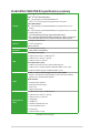
ProArt B760-CREATOR D4 specifications summary Total supports 3 x M.2 slots and 4 x SATA 6Gb/s ports* Intel® 13th & 12th Gen Processors M.2_1 slot (Key M), type 2242/2260/2280/22110 - Intel® 13th & 12th Gen processors support PCIe 4.0 x4 mode Intel® B760 Chipset Storage M.2_2 slot (Key M), type 2242/2260/2280/22110 (supports PCIe 3.0 x4 mode)** M.2_3 slot (Key M), type 2242/2260/2280/22110 (supports PCIe 4.0 x4 mode) 4 x SATA 6Gb/s ports * Intel® Rapid Storage Technology supports SATA RAID 0/1/5/10. ** M.
ProArt B760-CREATOR D4 specifications summary Fan and Cooling related 1 x 4-pin CPU Fan header 1 x 4-pin CPU OPT Fan header 1 x 4-pin AIO Pump header 4 x 4-pin Chassis Fan headers Power related 1 x 24-pin Main Power connector 1 x 8-pin +12V Power connector 1 x 4-pin +12V Power connector Storage related 3 x M.2 slots (Key M) 4 x SATA 6Gb/s ports Internal I/O Connectors USB 1 x USB 3.2 Gen 2x2 connector (supports USB Type-C®) 1 x USB 3.2 Gen 1 header supports 2 additional USB 3.2 Gen 1 ports 2 x USB 2.
ProArt B760-CREATOR D4 specifications summary ASUS Thermal Solution - Flexible M.
x • Specifications are subject to change without notice. Please refer to the ASUS website for the latest specifications.
Chapter 1: Product Introduction Product Introduction 1.1 Before you proceed 1 Take note of the following precautions before you install motherboard components or change any motherboard settings. • Unplug the power cord from the wall socket before touching any component. • Before handling components, use a grounded wrist strap or touch a safely grounded object or a metal object, such as the power supply case, to avoid damaging them due to static electricity.
1.2 Motherboard overview 22 5 4 1 4 2 12 24.4cm(9.6in) RGB_HEADER CPU_FAN CPU_OPT AIO_PUMP ATX_12V_1 PLUG_8PIN_PWR ADD_GEN 2_1 ATX_12V_2 DIGI+ VRM M.2_1(SOCKET3) CHA_FAN1 Intel Ethernet AUDIO RTL Ethernet ATX_PWR PCIE SATA X 4.0 X4 M.2_1(SOCKET3) 2242 2260 9 8 1st 22110 2280 5 30.
Max. Max. Power Current 1A 12W 1A 12W 1A 12W 1A 12W 1A 12W 1A 12W 1A 12W Header CPU_FAN CPU_OPT AIO_PUMP CHA_FAN1 CHA_FAN2 CHA_FAN3 CHA_FAN4 Default Speed Q-Fan Controlled Q-Fan Controlled Full-Speed Q-Fan Controlled Q-Fan Controlled Q-Fan Controlled Q-Fan Controlled Shared Control A A - FAN PWM FAN IN FAN PWR GND FAN PWM FAN IN FAN PWR GND The Fan headers allow you to connect fans to cool the system. GND FAN PWR FAN IN FAN PWM 4. Fan headers 5.
9. USB 3.2 Gen 1 header The USB 3.2 Gen 1 module is purchased separately. PIN 1 USB3+5V IntA_P1_SSRXIntA_P1_SSRX+ GND IntA_P1_SSTXIntA_P1_SSTX+ GND IntA_P1_DIntA_P1_D+ GND USB3+5V IntA_P2_SSRXIntA_P2_SSRX+ GND IntA_P2_SSTXIntA_P2_SSTX+ GND IntA_P2_DIntA_P2_D+ USB+5V USB_P1USB_P1+ GND NC 10. USB 2.0 headers The USB 2.0 headers allow you to connect USB modules for additional USB 2.0 ports. The USB 2.0 headers provide data transfer speeds of up to 480 Mb/s.
• Actual lighting and color will vary with LED strip. • If your LED strip does not light up, check if the RGB LED extension cable and the RGB LED strip are connected in the correct orientation, and the 12V connector is aligned with the 12V header on the motherboard. • The LED strip will only light up when the system is powered on. • The LED strip is purchased separately. 13.
PIN 1 TPM T_SPI_MOSI T_SPI_CLK GND F_BIOS_WP#_R S_SPI_TPM_CS2# S_SPI_TPM_IRQ# This header supports a Trusted Platform Module (TPM) system with a Serial Peripheral Interface (SPI), allowing you to securely store keys, digital certificates, passwords, and data. A TPM system also helps enhance network security, protects digital identities, and ensures platform integrity. F_SPI_HOLD#_R T_SPI_MISO F_SPI_CS0#_R +3V_SPI F2_SPI_CS1#_R S_PLTRST# VCCSPI 17. SPI TPM header SPI TPM module is sold separately. 18.
I2C_SCL I2C_SDA I2C_IRQ# RTD3_POWER_EN S_SLP_S0#_IDLE PERST_N WAKE# 20. Thunderbolt™ header The add-on Thunderbolt™ I/O card and Thunderbolt™ cables are purchased separately. • Please visit the official website of your purchased Thunderbolt card for more details on compatibility.
1.2.2 Rear panel connectors 1 2 8 3 9 10 4 5 9 11 6 7 12 13 1. DisplayPort. This port is for a DisplayPort-compatible device. 2. USB 2.0 ports. These Universal Serial Bus (USB) ports are for USB 2.0 devices. 3. Ethernet port. This port allows Gigabit connection to a Local Area Network (LAN) through a network hub. Refer to the table below for the Ethernet port LED indications. Ethernet port LED indications 4.
8. HDMI® port. This port is for a High-Definition Multimedia Interface (HDMI®) connector, and is HDCP compliant allowing playback of HD DVD, Blu-ray, and other protected content. 9. USB 3.2 Gen 1 (up to 5Gbps) port. This Universal Serial Bus (USB) port connects to a USB 3.2 Gen 1 device. 10. USB 3.2 Gen 2 (up to 10Gbps) ports (USB Type-C®). This Universal Serial Bus 3.2 (USB 3.2) port is for a USB 3.2 Gen 2 Type-C® device. 11. Optical S/PDIF out port.
1.3 Central Processing Unit (CPU) This motherboard comes with a LGA1700 socket designed for 13th Gen Intel® Core™ &12th Gen Intel® Core™, Pentium® Gold and Celeron® Processors. Unplug all power cables before installing the CPU. • Ensure that you install the correct CPU designed for LGA1700 socket only. DO NOT install a CPU designed for LGA1155, LGA1156, LGA1151, and LGA1200 sockets on the LGA1700 socket.
C Ensure to remove the CPU Socket lever protector on the lever latch before locking the lever latch under the retention tab. Failure to do so may cause damages to your system when installing the cooling system.
1.4 System memory This motherboard comes with four Double Data Rate 4 (DDR4) Dual Inline Memory Module (DIMM) sockets. The figure illustrates the location of the DDR4 DIMM sockets: DIMM_A1 DIMM_A2 DIMM_B1 DIMM_B2 Channel Sockets Channel A DIMM_A1 & DIMM_A2 Channel B DIMM_B1 & DIMM_B2 A DDR4 memory module is notched differently from a DDR, DDR2, or DDR3 module. DO NOT install a DDR, DDR2, or DDR3 memory module to the DDR4 slot. • You may install varying memory sizes in Channel A and Channel B.
Installing a DIMM 1 2 3 To remove a DIMM B ProArt B760-CREATOR D4 A 1-13
1.5 M.2 installation Supported M.2 type varies per motherboard. If the thermal pad on the M.2 heatsink becomes damaged, we recommend replacing it with a thermal pad with a thickness of 1.25mm. • The illustrations only show the installation steps for a single M.2 slot, the steps are the same for the other M.2 slots if you wish to install an M.2 to another M.2 slot. • Use a Phillips screwdriver when removing or installing the screws or screw stands mentioned in this section. • The M.
3. Install your M.2 to your M.2 slot. The steps may differ between installing M.2 of different lengths, please refer to the different types and their installation steps below: For 2280, 22110 length A. (optional) Remove the pre-installed removable M.2 Q-Latch screw at the 2280 length screw hole. Follow step A only when you wish to install an 22110 length M.2. B. (optional) Install the bundled M.2 rubber pad if you are installing a single sided M.2 storage device. DO NOT install the bundled M.
For 2242, 2260 length A. (optional) Remove the M.2 rubber pad. Follow this step only if you wish to install an M.2 to type 2242. B. (optional) If required, remove the pre-installed removable M.2 Q-Latch screw at the 2280 length screw hole. C. Install the M.2 Q-Latch to the M.2 length screw hole you wish to install your M.2 to. D. Rotate and adjust the M.2 Q-latch so that the handle points away from the M.2 slot. 1-16 E. Install your M.2 to the M.2 slot. F. Rotate the M.
4. Remove the plastic film from the thermal pads on the bottom of the heatsink. If the thermal pad on the M.2 heatsink becomes damaged, we recommend replacing it with a thermal pad with a thickness of 1.25mm. 5. Replace the heatsink. 6. Secure the heatsink using the screws removed previously.
1-18 Chapter 1: Product Introduction
BIOS and RAID Support 2.1 Knowing BIOS 2 The new ASUS UEFI BIOS is a Unified Extensible Interface that complies with UEFI architecture, offering a user-friendly interface that goes beyond the traditional keyboardonly BIOS controls to enable a more flexible and convenient mouse input. You can easily navigate the new UEFI BIOS with the same smoothness as your operating system. The term “BIOS” in this user manual refers to “UEFI BIOS” unless otherwise specified.
2.2 BIOS Setup program Use the BIOS Setup to update the BIOS or configure its parameters. The BIOS screens include navigation keys and brief onscreen help to guide you in using the BIOS Setup program. Entering BIOS at startup To enter BIOS Setup at startup, press or during the Power-On Self Test (POST). If you do not press or , POST continues with its routines. Entering BIOS Setup after POST To enter BIOS Setup after POST: • Press ++ simultaneously.
2.3 ASUS EZ Flash 3 The ASUS EZ Flash 3 feature allows you to update the BIOS without using an OS‑based utility. Ensure to load the BIOS default settings to ensure system compatibility and stability. Select the Load Optimized Defaults item under the Exit menu or press hotkey . To update the BIOS: • This function can support devices such as a USB flash disk with FAT 32/16 format and single partition only.
2.4 ASUS CrashFree BIOS 3 The ASUS CrashFree BIOS 3 utility is an auto recovery tool that allows you to restore the BIOS file when it fails or gets corrupted during the updating process. You can restore a corrupted BIOS file using a USB flash drive that contains the BIOS file. Recovering the BIOS 1. Download the latest BIOS version for this motherboard from https://www.asus.com/support/. 2. Rename the BIOS file as ASUS.CAP or PA760CD4.CAP and copy the renamed BIOS file to a USB flash drive. 3.
2.5 RAID configurations The motherboard comes with the Intel® Rapid Storage Technology that supports SATA RAID 0, RAID 1, RAID 5 and RAID 10 configuration. For more information on configuring your RAID sets, please refer to the RAID Configuration Guide which you can find at https://www.asus.com/support, or by scanning the QR code. RAID definitions RAID 0 (Data striping) optimizes two identical hard disk drives to read and write data in parallel, interleaved stacks.
2-6 Chapter 2: BIOS and RAID Support
Appendix Appendix Notices FCC Compliance Information Responsible Party: Address: Phone / Fax No: Asus Computer International 48720 Kato Rd., Fremont, CA 94538, USA (510)739-3777 / (510)608-4555 This device complies with part 15 of the FCC Rules. Operation is subject to the following two conditions: (1) This device may not cause harmful interference, and (2) this device must accept any interference received, including interference that may cause undesired operation.
Compliance Statement of Innovation, Science and Economic Development Canada (ISED) This device complies with Innovation, Science and Economic Development Canada licence exempt RSS standard(s). Operation is subject to the following two conditions: (1) this device may not cause interference, and (2) this device must accept any interference, including interference that may cause undesired operation of the device.
Declaration of compliance for product environmental regulation ASUS follows the green design concept to design and manufacture our products, and makes sure that each stage of the product life cycle of ASUS product is in line with global environmental regulations. In addition, ASUS disclose the relevant information based on regulation requirements. Please refer to http://csr.asus.com/Compliance.
France sorting and recycling information FR Cet appareil et ses accessoires se recyclent À DÉPOSER EN MAGASIN À DÉPOSER EN DÉCHÈTERIE OU Points de collecte sur www.quefairedemesdechets.fr Privilégiez la répara�on ou le don de votre appareil ! Safety Precautions Accessories that came with this product have been designed and verified for the use in connection with this product. Never use accessories for other products to prevent the risk of electric shock or fire.
Simplified UKCA Declaration of Conformity English ASUSTeK Computer Inc. hereby declares that this device is in compliance with the essential requirements and other relevant provisions of related UKCA Directives. Full text of UKCA declaration of conformity is available at: www.asus.com/support. Simplified EU Declaration of Conformity English ASUSTeK Computer Inc. hereby declares that this device is in compliance with the essential requirements and other relevant provisions of related Directives.
Warranty EN: ASUS Guarantee Information • ASUS offers a voluntary manufacturer’s Commercial Guarantee. • ASUS reserves the right to interpret the provisions of the ASUS Commercial Guarantee. • This ASUS Commercial Guarantee is provided independently and in addition to the statutory Legal Guarantee and in no way affects or limits the rights under the Legal Guarantee. CR: Informacije o ASUS jamstvu • ASUS dragovoljno nudi komercijalno proizvođačko jamstvo.
PG: Informações de Garantia ASUS • A ASUS oferece uma Garantia Comercial voluntária do fabricante. • A ASUS reserva o direito de interpretar as disposições da Garantia Comercial da ASUS. • Esta Garantia Comercial da ASUS é fornecida de forma independente além da Garantia Legal estatutária e não afeta nem limita de qualquer forma os direitos estabelecidos na Garantia Legal. Para consultar todas as informações sobre a garantia, visite https://www.asus.com/pt/support/.
ASUS contact information ASUSTeK COMPUTER INC. Address: 1F., No. 15, Lide Rd., Beitou Dist., Taipei City 112 ASUS COMPUTER INTERNATIONAL (America) Address: 48720 Kato Rd., Fremont, CA 94538, USA ASUS COMPUTER GmbH (Germany and Austria) Address: Harkortstrasse 21-23, 40880 Ratingen, Germany ASUSTeK (UK) LIMITED Address: 1st Floor, Sackville House, 143-149 Fenchurch Street, London, EC3M 6BL, England, United Kingdom Service and Support Visit our multi-language website at https://www.asus.com/support.