
User Manual


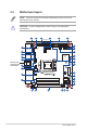

Table Of Contents
- Chapter 1
- Chapter 2
- Chapter 3
- BIOS setup
- 3.1 BIOS Setup program
- 3.2 Main menu
- 3.3 Advanced menu
- 3.3.1 Start ASUS EzFlash
- 3.3.2 PCH-FW Configuration
- 3.3.3 Trusted Computing
- 3.3.4 Platform Misc Configuration
- 3.3.5 CPU Configuration
- 3.3.6 System Agent (SA) Configuration
- 3.3.7 PCH Storage Configuration
- 3.3.8 Onboard Devices Configuration
- 3.3.9 ACPI Settings
- 3.3.10 LVDS Configuration
- 3.3.11 APM Configuration
- 3.3.12 NCT6116D Super IO Configuration
- 3.3.13 NCT6116D HW Monitor
- 3.3.14 Serial Port Console Redirection
- 3.3.15 Intel TXT Information
- 3.3.16 USB Configuration
- 3.3.17 NVMe Configuration
- 3.3.18 HDD Secure Erase
- 3.3.19 Dynamic Digital IO
- 3.3.20 Network Stack Configuration
- 3.4 Security menu
- 3.5 Boot menu
- 3.6 Save & Exit menu
- 3.7 Event Logs
- BIOS setup
- Appendix

Q370I-IM-A R3.0
2-2
17.0cm(6.7in)
17.0cm(6.7in)
EATXPWR
DDR4 SO-DIMM_B1*
DDR4 SO-DIMM_A1*
M.2_(SOCKET3)
F_PANEL
SPEAKER
CHASSIS
AT_ATX_SEL
I
2
C
WDT_EN
BKLTEN_SEL
LCD_BLKT_PANEL
SPDIF_OUT
DIS_ME
SATA6G_3 SATA6G_4 SATA6G_5 SATA6G_6
CLRTC
ALC
897
AAFP
KBMS
USB9111213
DP12
DVI
COM1
AUDIO
Super
I/O
LAN2_U32G1_56
LAN1_U32G1_34
VCC_PWR_SEL
32Mb
BIOS
LGA1151
U32G1_12
U32G1_10
USB78
Intel
®
Q370
Intel
®
I219LM
PCIEX16
ATX12V
CPU_FAN
CHA_FAN
LPC_DEBUG
COM2
COM4
COM3
EDP
GPIO_CON
BATT_CON
WGI
211AT
LVDS
TPM
ASM1480
M.2(WIFI)
2260
2242
2280
BKLPWR_SEL
15
14
16
17
13
12
11
10
7
1
8
9
19
18
20
22 2123
24
26
28
27
32
31
30
29
25
54 62 31
2.2 Motherboard layout
Place this side
towards the rear
of the chassis
NOTE: Place four screws into the holes indicated by circles to secure the
motherboard to the chassis.
CAUTION! Do not overtighten the screws! Doing so can damage the
motherboard.