
User's Manual


Q370M-IM-A
2-2
PCI
PCIEX1_1
PCIEX1_2
SPEAKER
CHASSIS
DIS_ME
CLRTC
F_PANEL
LPC_DEBUG
LPT
U32G1_56
U32G1_78
AAFP
MONO_OUT
EATX12V
EATXPWR
CHA_FAN2
CPU_FAN
CHA_FAN1
BATTERY
PCIEX16
Super
I/O
ASM
1083
ALC
887
DIGI
+VRM
24.4cm(9.6in)
24.4cm(9.6in)
LGA1151
Intel
®
Q370
Intel
®
I219LM
DDR4 DIMM_B1 (64bit, 288-pin module)
2280 2260 2242
2280 2260 2242
M.2_2(SOCKET3)
M.2_2(SOCKET3)
PCIE SATA IRST
X4 X V
M.2_1(SOCKET3)
PCIE SATA IRST
X4 VV
M.2_1(SOCKET3)
DDR4 DIMM_B2* (64bit,288-pin module)
DDR4 DIMM_A1 (64bit, 288-pin module)
DDR4 DIMM_A2* (64bit, 288-pin module)
AUDIO
KBMS
DP12
LAN_USB910
U32G2_12
U32G2_34
128Mb
BIOS
64Mb
BIOS
SATA6G_4 SATA6G_3
SATA6G_6 SATA6G_5
SATA6G_2 SATA6G_1
HDMI
VGA
USB1112
COM1 COM2
M.2(WIFI)
1 432 51
1
810 912 11
2
7
1
715 1416
6
6
31718 13
19
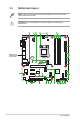
2.2 Motherboard layout
Place this side
towards the rear
of the chassis
NOTE: Place eight screws into the holes indicated by circles to secure the
motherboard to the chassis.
CAUTION! Do not overtighten the screws! Doing so can damage the
motherboard.