Industrial Motherboard Q670EM-IM-A
E21753 First Edition March 2023 Copyright © 2023 ASUSTeK COMPUTER INC. All Rights Reserved. No part of this manual, including the products and software described in it, may be reproduced, transmitted, transcribed, stored in a retrieval system, or translated into any language in any form or by any means, except documentation kept by the purchaser for backup purposes, without the express written permission of ASUSTeK COMPUTER INC. (“ASUS”).
Contents Chapter 1 Product Overview 1.1 Package contents......................................................................... 1-1 1.2 Features......................................................................................... 1-1 1.3 Specifications................................................................................ 1-2 Chapter 2: Motherboard Information 2.1 Before you proceed...................................................................... 2-1 2.2 Motherboard layout..
3.3.14 Onboard Devices Configuration..................................... 3-15 3.3.15 APM Configuration......................................................... 3-16 3.3.16 EZ-Flash........................................................................ 3-17 3.3.17 IO Expander Configuration............................................ 3-17 3.3.18 Watchdog Timer............................................................. 3-18 3.4 Hardware Monitor menu...............................................
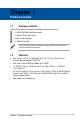
Chapter 1 Product overview 1.1 Package contents Check your industrial motherboard package for the following items. 1 x ASUS Q670EM-IM-A Motherboard 1 x Serial ATA 6.0 Gb/s cable 2 x M.2 screw packages 1 x ASUS I/O Shield If any of the above items is damaged or missing, contact your distributor or sales representative immediately. 1.2 Features • Intel® socket 1700 for 12th Gen Intel® Core™ i9/ i7/ i5/ i3, Pentium®, and Celeron® processors Max.
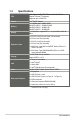
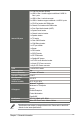
1.3 Specifications CPU Chipset Memory Display LGA1700 for Intel® 12th/13th Gen. Core™ i9/ i7/ i5/ i3/ Pentium®/Celeron® Processors Supports up to 125W TDP Intel® Q670E Chipset 4 x U-DIMM, Max. 128GB, DDR5 4400MT/s (2DPC - 1DIMM 1R&2R) 4000MT/s (2DPC – 2DIMM 1R) 3600MT/s (2DPC – 2DIMM 2R) 4 x DisplayPort, supports DP++ 1.4, up to 3840 x 2160 @ 60Hz 1 x PCIe 5.0 x16 Slot (x16 mode / x8+x8 mode) 1 x PCIe 4.0 x4 Slot (x4 mode) 1 x PCIe 5.
9 x COM Port headers (RS232) 1 x USB 3.2 Gen 1 header supports additional 2 USB 3.2 Gen 1 ports 1 x USB 3.2 Gen 1 vertical connector 2 x USB 2.0 headers support additional 4 x USB 2.
1-4 Q670EM-IM-A
Chapter 2 Motherboard information 2.1 Before you proceed Take note of the following precautions before you install motherboard components or change any motherboard settings. • Unplug the power cord from the wall socket before touching any component. • Before handling components, use a grounded wrist strap or touch a safely grounded object or a metal object, such as the power supply case, to avoid damaging them due to static electricity.
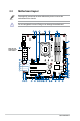
2.2 Motherboard layout Place eight (8) screws into the holes indicated by circles to secure the motherboard to the chassis. Do not overtighten the screws! Doing so can damage the motherboard.
Connectors/Jumpers/Slots 1. CPU and Chassis Fan headers (4-pin CPU_FAN, 4-pin CHA_FAN1-3) 2. ATX Power connectors (24-pin ATX_PWR, 8-pin EATX12V) 3. M.2 socket 3 (M.2(SOCKET3)) 4. Intel® LGA1700 CPU socket 5. DDR5 U-DIMM slots 6. USB 3.2 Gen 1 connector (20-1 pin U32G1_910) 7. SATA 6.0Gb/s ports (7-pin SATA6G_1-7) 8. SPI TPM header (14-1 pin TPM) 9. System Panel header (10-1 pin F_PANEL) 10. Chassis Intrude header (4-1 pin CHASSIS) 11. Serial Port connectors (10-1 pin COM2-10) 12.
2.3 Central Processing Unit (CPU) The motherboard comes with a surface mount LGA1700 socket designed for the 13th Gen Intel® Core™ and 12th Gen Intel® Core™ i9/ i7/ i5/ i3, Pentium®, and Celeron® processors. LGA1700 Unplug all power cables before installing the CPU. 2-4 • Upon purchase of the motherboard, ensure that the PnP cap is on the socket and the socket contacts are not bent.
2.3.
4 5 2-6 Q670EM-IM-A
2.3.2 CPU heatsink and fan assembly installation Apply Thermal Interface Material to the CPU cooling system and CPU before you install the cooling system, if necessary.
To uninstall the CPU heatsink and fan assembly 1 A B B A 2-8 Q670EM-IM-A
2.4 System memory The motherboard comes with Dual Inline Memory Modules (DIMM) slots designed for DDR5 (Double Data Rate 5) memory modules. DIMM_A1 DIMM_A2 DIMM_B1 DIMM_B2 A DDR5 memory module is notched differently from a DDR, DDR2, DDR3, or DDR4 module. DO NOT install a DDR, DDR2, DDR3, or DDR4 memory module to the DDR5 slot.
2.5 1. Jumpers COM1 Ring/+5V/+12V selection (6-pin COM1_SEL) This jumper allows you to select 5V or 12V depending on your COM device. COM1_SEL 2 1 +12V Setting Pins +12V 1-2 +5V 3-4 Ring (Default) 5-6 Connector type 2-10 4 3 +5V 6 5 RI (Default) HEADER 2x3p, 2.
2. AT/ATX mode selection (3-pin AT_ATX_SEL) In ATX mode (default), you will need to manually press the power button to turn on the system power. In AT mode, the board will automatically turn on when system power is connected. AT_ATX_SEL 1 2 ATX mode (Default) Pins 1-2 (Default) 2-3 Connector type 3. 2 3 AT mode Description ATX mode AT mode HEADER 1x3p, 2.54mm pitch, S/T Disable ME jumper (3-pin DIS_ME) This jumper allows you to enable or disable the Intel® ME function.
4. Chassis intrusion header (4-1 pin CHASSIS) This header is for a chassis-mounted intrusion detection sensor or switch. Connect one end of the chassis intrusion sensor or switch cable to this connector. The chassis intrusion sensor or switch sends a high-level signal to this connector when a chassis component is removed or replaced. The signal is then generated as a chassis intrusion event. Connector type 2-12 +5VSB_MB Chassis Signal GND CHASSIS PIN 1 HEADER 4p, K2, 2.
5. Clear CMOS header (2-pin CLRTC) This header allows you to clear the CMOS RTC RAM data of the system setup information such as date, time, and system passwords. CLRTC +3V_BAT_RTC GND PIN 1 Connector type HEADER 1x2p, 1.25mm pitch, S/T To erase the RTC RAM: 1. Turn OFF the computer and unplug the power cord. 2. Use a metal object such as a screwdriver to short the two pins. 3. Plug the power cord and turn ON the computer. 4.
2.6 Connectors 2.6.1 Rear panel connectors 1. DisplayPort. These ports are for DisplayPort-compatible devices. 2. Serial port (COM). This port connects a modem or other device that conforms with serial specification. 3. LAN (RJ-45) port. This port allows Gigabit connection to a Local Area Network (LAN) through a network hub. LAN port LED indications Activity/Link LED Status Off Orange Orange (Blinking) Orange (Blinking then steady) 4.
5. Line In port (light blue). This port connects to the tape, CD, DVD player, or other audio sources. 6. Line Out port (lime). This port connects to a headphone or a speaker. In the 4 and 5.1 channel configurations, the function of this port becomes Front Speaker Out. 7. USB 3.2 Gen 1 (up to 5Gbps) ports (blue, Type-A). These 9-pin Universal Serial Bus (USB) ports are for USB 3.2 Gen 1 devices. 8. USB 3.2 Gen 2 (up to 10Gbps) ports (teal blue, Type-A).
2.6.2 1. Internal connectors LPT header (26-1 pin LPT) LPT_XAFD# LPT_ERROR# LPT_XINIT# LPT_XSLIN# GND GND GND GND GND GND GND GND The LPT (Line Printing Terminal) connector supports devices such as a printer. LPT standardizes as IEEE 1284, which is the parallel port interface on IBM PC-compatible computers. PIN 2 PIN 1 PIN 25 LPT_XSTB# LPT_XPD0 LPT_XPD1 LPT_XPD2 LPT_XPD3 LPT_XPD4 LPT_XPD5 LPT_XPD6 LPT_XPD7 LPT_ACK# LPT_BUSY LPT_PE LPT_SLCT LPT 2. USB 3.
3. USB 3.2 Gen 1 vertical connector (U32G1_8) Connect a USB 3.2 Gen 1 device to this connector. This connector complies with USB 3.2 Gen 1 specifications and provide faster data transfer speeds of up to 5 Gbps, faster charging time for USB-chargeable devices, optimized power efficiency, and backward compatibility with USB 2.0. U32G1_8 4. USB 2.0 connector (10-1 pin USB_1112, USB_713) This header is for an USB 2.0 port. Connect the USB cable to this header. This USB header complies with USB 2.
5. General purpose input/output connector (10-pin GPIO_CON) GND GPIO8 GPIO6 GPIO4 GPIO2 This connector is for a general purpose input/output module which allows you to customize the digital signal input/output. GPIO_CON +3V GPIO7 GPIO5 GPIO3 GPIO1 PIN 1 Connector type 6. WAFER HD 2x5p, 2.
7. CPU and Chassis Fan headers (4-pin CPU_FAN, 4-pin CHA_FAN1-3) Connect the fan cables to the fan headers on the motherboard, ensuring that the black wire of each cable matches the ground pin of the header. B C CHA_FAN1 CHA_FAN3 CHA_FAN2 A C D CHA FAN PWM CHA FAN IN CHA FAN PWR GND A CPU_FAN B D Connector type CPU FAN PWM CPU FAN IN CPU FAN PWR GND WAFER HD 4p, 2.54mm pitch, S/T Do not forget to connect the fan cables to the fan headers.
9. System Panel header (10-1 pin F_PANEL) This header supports several chassis-mounted functions. PWR_BTN PLED+ PLEDPWRBTN#_PANEL GND +PWR_LED PIN 2 PIN 1 +HDD_LED Connector type PIN 9 HDD_LED+ HDD_LEDGND O_RSTCON#_PR NC F_PANEL RESET Header 2x5p, K10, 2.54mm pitch • System power LED (2-pin PWR_LED) • This 2-pin header is for the system power LED. Connect the chassis power LED cable to this header.
10. Speaker header (4-pin SPEAKER) The 4-pin header is for the chassis-mounted system warning speaker. The speaker allows you to hear system beeps and warnings. SPEAKER +5V GND GND Speaker Out PIN 1 Connector type HEADER 1x4p, 2.54mm pitch, S/T 11. M.2 socket 3 (M.2(SOCKET3)) This socket allows you to install an M.2 SSD module. M.2(SOCKET3) • The M.2 SSD module is purchased separately. • This socket supports M Key and 2242/2260/2280 storage devices.
12. M.2 Wi-Fi (M.2(WIFI)) This socket connects to an M.2 Wi-Fi device. M.2(WIFI) The M.2 Wi-Fi module is purchased separately. 13. Serial Port connectors (10-1 pin COM2-10) B C D E F G H A B C D Connector type E F G H I I COM2 COM3 COM4 COM5 COM6 COM7 COM8 COM9 COM10 PIN 1 DCD# TXD GND RTS# Ring A RXD DTR# DSR# CTS# These headers are for serial (COM) ports. Connect the serial port cables to these headers, then install the module to a slot opening at the back of the system chassis.
14. Digital Audio header (4-1 pin SPDIF_OUT) This header is for an additional Sony/Philips Digital Interface (S/PDIF) port. Connect the S/PDIF Out module cable to this header, then install the module to a slot opening at the back of the system chassis. SPDIF_OUT Connector type SPDIFOUT GND +5V PIN 1 HEADER 1x4p, K2, 2.54mm pitch The SPDIF Out module is purchased separately. 15. I2C header (6-1 pin I2C) PWR 3.
16. Front Panel Audio header (10-1 pin AAFP) PIN 1 A_JD_HPOUT PIN 2 PIN 10 PIN 9 A_FMIC1_L A_FMIC1_R A_HPOUT_R A_JD_FRONT A_HPOUT_L AAFP A_GND NC A_JD_FMIC1 This header is for a chassis-mounted front panel audio I/O module that supports HD Audio standard. Connect one end of the front panel audio I/O module cable to this header. Connector type 2-24 HEADER 2x5p, K8, 2.
17. ATX Power connectors (24-pin ATX_PWR, 8-pin EATX12V) Correctly orient the ATX power supply plugs into these connectors and push down firmly until the connectors completely fit. A EATX12V +12V +12V +12V +12V PIN 1 GND GND GND GND A B B ATX_PWR +3 Volts +12 Volts +12 Volts +5V Standby Power OK GND +5 Volts GND +5 Volts GND +3 Volts +3 Volts GND +5 Volts +5 Volts +5 Volts -5 Volts GND GND GND PSON# GND -12 Volts +3 Volts PIN 1 DC Mode ATXPWR Pins 1 2 3 4 5 6 7 8 9 10 11 12 Signal +3.3V out +3.
18. Keyboard and Mouse Port connector (8-pin KBMS_CON) O_KB_CLK_R O_KB_DATA_R GND +5V_ZPS2 The Keyboard and Mouse Port connector allows you to connect a PS/2 keyboard and mouse.
2.7 1. Slot PCI Express x16 slots This motherboard supports two PCIe x16 graphics cards that comply with the PCI Express specification. 2. PCI Express x4 slots This motherboard supports three PCIe x4 network cards, SCSI cards and other cards that comply with the PCI Express specification.
2-28 Q670EM-IM-A
Chapter 3 BIOS setup Scan the QR code to view the BIOS update guide. 3.1 BIOS Setup program Use the BIOS Setup program to configure its parameters. The BIOS screens include navigation keys and brief online help to guide you in using the BIOS Setup program. Entering BIOS Setup at startup Press or during the Power-On Self Test (POST). If you do not press or , POST continues with its routines. Entering BIOS Setup after POST • Press ++ simultaneously.
BIOS menu screen The menu bar on top of the screen has the following main items: Main For changing the basic system configuration. Advanced For changing the advanced system settings. Hardware Monitor For displaying the system temperatures, fan and power status, and changing smart fan settings. Security For configuring the system security settings. Boot For changing the system boot configuration. Exit For selecting the save options and default options.
3.3.2 Trusted Computing Security Device Support Allows you to enable or disable BIOS support for security device. Configuration options: [Disabled] [Enabled] The following items appear when a TPM device is installed on your motherboard. SHA256 PCR Bank Configuration options: [Disabled] [Enabled] SHA384 PCR Bank Configuration options: [Disabled] [Enabled] SM3_256 PCR Bank Configuration options: [Disabled] [Enabled] Pending operation Allows you to schedule an operation for security device.
3.3.3 CPU Configuration The items in this menu show CPU-related information the BIOS automatically detects. Intel (VMX) Virtualization Technology This item, when set to [enabled], will allow a VMM to utilize the additional hardware capacities provided by Vanderpool Technology. Configuration options: [Disabled] [Enabled] VT-d Configuration options: [Disabled] [Enabled] CPU - Power Management Control This item allows you to manage and configure the CPU’s power.
Power Limit 2 Override Allows you to enable or disable Power Limit 2 Override. If this option is set to [Disabled], BIOS will program the default values for Power Limit 2. Configuration options: [Enabled] [Disabled] The following item appears only when you set Power Limit 2 Override to [Enabled]. Power Limit 2 Allows you to configure Power Limit 2 value in milliwatts. 3.3.4 Graphics Configuration This item allows you to select a primary display from IGFX and PEG graphical devices.
3.3.6 PCI Express Configuration This item allows you to configure PCI Express settings. PCIEx16(G5)_1 Slot Allows you to configure the PCI Express Root Port settings. PCIEx16(G5)_1 Slot Allows you to enable or disable the PCI Express Root Port. Configuration options: [Disabled] [Enabled] The following items appear only when you set PCIEx16(G5)_1 Slot to [Enabled]. PCIe Speed Allows you to configure the PCIe speed.
Detect Non-Compliance Device When set to [Enabled], this item allows you to detect the non-compliance device in PEG. Configuration options: [Disabled] [Enabled] PCIEx4(G4)_1 Slot Allows you to configure the PCI Express Root Port settings. PCIEx4(G4)_1 Slot Allows you to enable or disable the PCI Express Root Port. Configuration options: [Disabled] [Enabled] The following items appear only when you set PCIEx4(G4)_1 Slot to [Enabled]. PCIe Speed Allows you to configure the PCIe speed.
Detect Non-Compliance Device When set to [Enabled], this item allows you to detect the non-compliance device in PEG. Configuration options: [Disabled] [Enabled] 3.3.7 Super IO Configuration Serial Port 1 Configuration This item allows you to set parameters of Serial Port 1 (COMA). Serial Port Allows you to enable or disable the serial port (COM). Configuration options: [Disabled] [Enabled] The following item appears only when you set Serial Port to [Enabled]. COM1 Control Allows you to select COM1 mode.
Serial Port Allows you to enable or disable the serial port (COM). Configuration options: [Disabled] [Enabled] Serial Port 10 Configuration This item allows you to set parameters of Serial Port 5 (COMJ).Serial Port Allows you to enable or disable the serial port (COM). Configuration options: [Disabled] [Enabled] Parallel Port Configuration This item allows you to set parameters of Parallel Port (LPT/LPTE). Parallel Port Allows you to enable or disable the Parallel Port (LPT/LPTE).
Bits per second Allows you to select serial port transmission speed. The speed must be matched on the other side. Long or noisy lines may require lower speeds. Configuration options: [9600] [19200] [38400] [57600] [115200] Data Bits Configuration options: [7] [8] Parity A parity bit can be sent with the data bits to detect some transmission errors. [None] Disables parity check. [Even] Parity bit is 0 if the num of 1’s in the data bits is even.
Putty KeyPad Allows you to select FunctionKey and KeyPad on Putty. Configuration options: [VT100] [LINUX] [XTERMR6] [SCO] [ESCN] [VT400] COMB(Pci Bus0, Dev0, Func0) (Disabled) The following items can be configured only when AMT is provisioned. Console Redirection Settings Terminal Type [VT100] ASCII char set. [VT100Plus] Extends VT100 to support color, function keys, etc. [VT-UTF8] Uses UTF8 encoding to map Unicode chars onto 1 or more bytes. [ANSI] Extended ASCII char set.
Flow Control Flow control can prevent data loss from buffer overflow. When sending data, if the receiving buffers are full, a “stop” signal can be sent to stop the data flow. Once the buffers are empty, a “start” signal can be sent to re-start the flow. Hardware flow control uses two wires to send start/stop signals. Configuration options: [None] [Hardware RTS/CTS] VT-UTF8 Combo Key Support Allows you to enable or disable VT-UTF8 Combination Key Support for ANSI/ VT100 terminals.
3.3.10 VMD setup menu Enable VMD controller This item allows you to disable or enable VMD controller. Configuration options: [Disabled] [Enabled] 3.3.11 Network Stack Configuration Network Stack This item allows you to disable or enable the UEFI Network Stack. Configuration options: [Disabled] [Enabled] The following items appear only when you set Network Stack to [Enabled]. IPv4 PXE Support Allows you to enable or disable IPv4 PXE boot support. If disabled, IPv4 PXE boot support will be unavailable.
U32G2_3 Allows you to enable or disable USB port. Once set to [Disabled], any USB devices plugged into the connector will not be detected by BIOS or OS. Configuration options: [Disabled] [Enabled] U32G2_4 Allows you to enable or disable USB port. Once set to [Disabled], any USB devices plugged into the connector will not be detected by BIOS or OS. Configuration options: [Disabled] [Enabled] U32G1_5 Allows you to enable or disable USB port.
3.3.13 NVMe Configuration The NVMe Configuration menu displays the NVMe controller and drive information of the devices connected and allows you to configure NVMe device options settings. 3.3.14 Onboard Devices Configuration HD Audio Allows you to control detection of the HD-Audio device. [Enabled] Enables the HD Audio Device unconditionally. [Disabled] Disables the HD Audio Device unconditionally.
3.3.15 APM Configuration This item allows you to configure APM (Advanced Power Management) settings. ErP Ready Allows BIOS to switch off some power at S5 to get the system ready for ErP requirement. When set to [Enabled], all other PME options will be switched off. Configuration options: [Disabled] [Enabled] Restore AC Power Loss Allows you to select AC power state when power is re-applied after a power failure.
Wake up hour Allows you to enter a natural number within 0-23 for hour. For example, enter 3 for 3:00 am and 15 for 3:00 pm. Wake up minute Allows you to enter a natural number within 0-59 for minute. Wake up second Allows you to enter a natural number within 0-59 for second. The following items appear when you set Power On By RTC to [Monthly event]. Day of the Month Allows you to select the day of the month when the system is to wake up.
3.3.18 Watchdog Timer Watchdog Support Configuration options: [Disabled] [Enabled] The following items appear when you set Watchdog Support to [Enable]. Watchdog Count mode Allows you to select Watchdog Timer I count mode. Configuration options: [Second Mode] [Minute Mode] Watchdog Timer Allows you to set the Watchdog Timer I Time-out value. 3.4 Hardware Monitor menu The Hardware Monitor menu displays the system temperatures, fan and power status, and allows you to configure the smart fan.
Chassis Fan 3 Setting Chassis Fan3 Temperature 1(~4) Allows you to set the value of temperature1(~4). Chassis Fan3 FD/RPM 1(~4) Allows you to set the value of Fan Duty/PRM 1(~4) when temperature is T1(~4). CPU Fan Setting CPU Fan Temperature 1(~4) Allows you to set the value of temperature1(~4). CPU Fan FD/RPM 1(~4) Allows you to set the value of Fan Duty/PRM 1(~4) when temperature is T1(~4). 3.5 Security menu The Security menu allows a new password to be created or a current password to be changed.
3.5.2 User Password If you have set a user password, you must enter the user password for accessing the system. To set a user password: 1. Select the User Password item and press . 2. From the Create New Password box, key in a password, then press . 3. Confirm the password when prompted. To change a user password: 1. Select the User Password item and press . 2. From the Enter Current Password box, key in the current password, then press . 3.
3.6 Boot menu The items in the Boot menu allow you to change the system boot options. Boot Configuration CHASSIS INTRUDE Allows you to enable or disable CHASSIS INTRUDE. Configuration options: [Disabled] [Enabled] Setup Prompt Timeout Allows you to set the number of seconds to wait for setup activation key. 65535(0xFFFF) means indefinite waiting. Post Time Delay Allows you to set the delay for specific situation needs. For example, HDD spin up time (Delay time = value * 500ms).
3.7 Exit menu The items in the Exit menu allow you to save or discard your changes to the BIOS items. Save Changes and Exit Allows you to exit the system setup program after saving the changes. Discard Changes and Exit Allows you to exit the system setup program without saving the changes you made. When you select this option or if you press , a confirmation window appears. Select Yes to discard changes and exit. Save Changes and Reset Allows you to reset the system setup after saving the changes.
Appendix Notices FCC Compliance Information Responsible Party: Asus Computer International Address: 48720 Kato Rd., Fremont, CA 94538, USA Phone / Fax No: (510)739-3777 / (510)608-4555 This device complies with part 15 of the FCC Rules. Operation is subject to the following two conditions: (1) This device may not cause harmful interference, and (2) this device must accept any interference received, including interference that may cause undesired operation.
Compliance Statement of Innovation, Science and Economic Development Canada (ISED) This device complies with Innovation, Science and Economic Development Canada licence exempt RSS standard(s). Operation is subject to the following two conditions: (1) this device may not cause interference, and (2) this device must accept any interference, including interference that may cause undesired operation of the device.
REACH Complying with the REACH (Registration, Evaluation, Authorisation, and Restriction of Chemicals) regulatory framework, we published the chemical substances in our products at ASUS REACH website at http://csr.asus.com/english/REACH.htm. DO NOT throw the motherboard in municipal waste. This product has been designed to enable proper reuse of parts and recycling.
English ASUSTeK Computer Inc. hereby declares that this device is in compliance with the essential requirements and other relevant provisions of related Directives. Full text of EU declaration of conformity is available at: www.asus.com/support Français AsusTek Computer Inc. déclare par la présente que cet appareil est conforme aux critères essentiels et autres clauses pertinentes des directives concernées. La déclaration de conformité de l’UE peut être téléchargée à partir du site Internet suivant : www.
Service and Support Visit our multi-language website at https://www.asus.com/support/ Manufacturer Address, City Authorized Representative in Europe Address Country Authorized Representative in United Kingdom Address ASUSTek COMPUTER INC. Country United Kingdom Appendix 1F., No. 15, Lide Rd., Beitou Dist.
A-6 Q670EM-IM-A