
User Manual

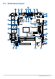
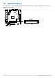
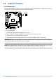
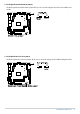
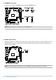
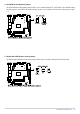
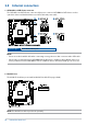
Table Of Contents
- About this manual
- Chapter 1: Specifications Summary
- Chapter 2: Product Introduction
- Chapter 3: Upgrading your Industrial motherboard
- Chapter 4: BIOS Setup
- 4.1 Getting to know your BIOS
- 4.2 BIOS setup program
- 4.3 Main Menu
- 4.4 Advanced menu
- 4.4.1 Graphic Configuration
- 4.4.2 CPU Configuration
- 4.4.3 Watchdog Timer
- 4.4.4 CSM Configuration
- 4.4.5 Super IO Configuration
- 4.4.6 Serial Console Redirection
- 4.4.7 SATA Configuration
- 4.4.8 USB Configuration
- 4.4.9 Trusted Computing
- 4.4.10 NVMe Configuration
- 4.4.11 Onboard Devices Configuration
- 4.4.12 APM Configuration
- 4.4.13 Network Stack Configuration
- 4.4.14 AMD CBS
- 4.4.15 AMD PBS
- 4.4.16 EZ-Flash
- 4.5 Hardware Monitor menu
- 4.6 Security
- 4.7 Boot menu
- 4.8 Exit menu
- 4.9 Updating your BIOS
- Appendix

20
Industrial motherboard
2.5 Internal connectors
1. SATA 6Gb/s & SATA Power connector
The SATA 6Gb/s and SATA Power connectors allow you to connect a SATA DOM or SATA devices such as
optical disc drives and hard disk drives via a SATA cable and power cable.
Connector type
Wafer HD 4P, 2.0mm pitch
NOTE:
• Ensure to use the bundled cable when connecting a storage device to this connector with a SATA cable.
• We strongly recommend using a SATA DOM with the dimensions of 40.4 x 21.03 x 10.4 mm (W x L x H)
when you wish to install a SATA DOM as well as a USB flash drive to the Internal USB Type-A connector.
2. M.2 Wi-Fi slot
The M.2 Wi-Fi slot allows you to install an M.2 Wi-Fi module (E-key, type 2230).
NOTE: The M.2 Wi-Fi module is purchased separately.