
User Manual
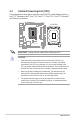
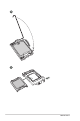
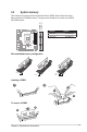
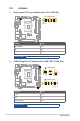
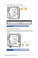
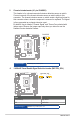
Table Of Contents
- Chapter 1
- Chapter 2
- Chapter 3
- BIOS setup
- 3.1 BIOS Setup program
- 3.2 Main menu
- 3.3 Advanced menu
- 3.3.1 LVDS Configuration
- 3.3.2 PCH-FW Configuration
- 3.3.3 Trusted Computing
- 3.3.4 CPU Configuration
- 3.3.5 Graphics Configuration
- 3.3.6 Power Management
- 3.3.7 PCI Express Configuration
- 3.3.8 AMT Configuration
- 3.3.9 Super IO Configuration
- 3.3.10 Serial Console Redirection
- 3.3.11 SATA Configuration
- 3.3.12 VMD setup menu
- 3.3.13 Network Stack Configuration
- 3.3.14 USB Configuration
- 3.3.15 NVMe Configuration
- 3.3.16 Onboard Devices Configuration
- 3.3.17 Miscellaneous
- 3.3.18 APM Configuration
- 3.3.19 EZ-Flash
- 3.3.20 IO Expander Configuration
- 3.3.21 Watchdog Timer
- 3.4 Hardware Monitor menu
- 3.5 Security menu
- 3.6 Boot menu
- 3.7 Exit menu
- BIOS setup
- Appendix

R680EI-IM-A
2-10
2.5 Jumpers
Setting Pins
3V (Default) 1-2
5V 3-4
12V 5-6
1. Display panel VCC power selection (6-pin VCC_PWR_SEL)
R680EI-IM-A
3
12V
2
5V
1
3V
(Default)
VCC_PWR_SEL
Connector type
HEADER 2 x 3p, 2.54mm pitch, S/T
2. COM1/2 Ring/+5V/+12V selection (6-pin COM1_SEL, COM2_SEL)
Setting Pins
+12V 1-2
+5V 3-4
Ring (Default) 5-6
R680EI-IM-A
RI
(Default)
+5V+12V
COM1_SEL
COM2_SEL
12 34 56
RI
(Default)
+5V+12V
1
2
3
4
5
6
B
A
A
B
Connector type
HEADER 2x3p, 2.54mm pitch, S/T