
User Manual

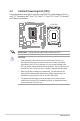
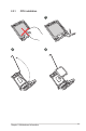


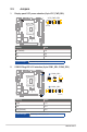


Table Of Contents
- Chapter 1
- Chapter 2
- Chapter 3
- BIOS setup
- 3.1 BIOS Setup program
- 3.2 Main menu
- 3.3 Advanced menu
- 3.3.1 LVDS Configuration
- 3.3.2 PCH-FW Configuration
- 3.3.3 Trusted Computing
- 3.3.4 CPU Configuration
- 3.3.5 Graphics Configuration
- 3.3.6 Power Management
- 3.3.7 PCI Express Configuration
- 3.3.8 AMT Configuration
- 3.3.9 Super IO Configuration
- 3.3.10 Serial Console Redirection
- 3.3.11 SATA Configuration
- 3.3.12 VMD setup menu
- 3.3.13 Network Stack Configuration
- 3.3.14 USB Configuration
- 3.3.15 NVMe Configuration
- 3.3.16 Onboard Devices Configuration
- 3.3.17 Miscellaneous
- 3.3.18 APM Configuration
- 3.3.19 EZ-Flash
- 3.3.20 IO Expander Configuration
- 3.3.21 Watchdog Timer
- 3.4 Hardware Monitor menu
- 3.5 Security menu
- 3.6 Boot menu
- 3.7 Exit menu
- BIOS setup
- Appendix

R680EI-IM-A
2-4
IMPORTANT! Unplug all power cables before installing the CPU.
CAUTION!
• Upon purchase of the motherboard, ensure that the PnP cap is on
the socket and the socket contacts are not bent. Contact your retailer
immediately if the PnP cap is missing, or if you see any damage to the
PnP cap/socket contacts/motherboard components. The manufacturer will
shoulder the cost of repair only if the damage is shipment/transit-related.
• Keep the cap after installing the motherboard. The manufacturer will
process Return Merchandise Authorization (RMA) requests only if the
motherboard comes with the cap on the LGA1200 socket.
• The product warranty does not cover damage to the socket contacts
resulting from incorrect CPU installation/removal, or misplacement/loss/
incorrect removal of the PnP cap.
2.3 Central Processing Unit (CPU)
The motherboard comes with a surface mount LGA1700 socket designed for the
Intel
®
12
th
Generation Intel
®
Core™ i9 / Core™ i7 / Core™ i5 / Core™ i3, Pentium
®
,
and Celeron
®
processors.
R680EI-IM-A
LGA1700