
User Manual
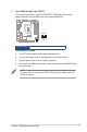
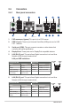
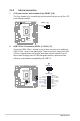
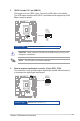
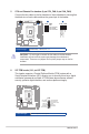
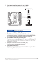

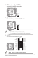
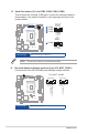
Table Of Contents
- Chapter 1
- Chapter 2
- Chapter 3
- BIOS setup
- 3.1 BIOS Setup program
- 3.2 Main menu
- 3.3 Advanced menu
- 3.3.1 LVDS Configuration
- 3.3.2 PCH-FW Configuration
- 3.3.3 Trusted Computing
- 3.3.4 CPU Configuration
- 3.3.5 Graphics Configuration
- 3.3.6 Power Management
- 3.3.7 PCI Express Configuration
- 3.3.8 AMT Configuration
- 3.3.9 Super IO Configuration
- 3.3.10 Serial Console Redirection
- 3.3.11 SATA Configuration
- 3.3.12 VMD setup menu
- 3.3.13 Network Stack Configuration
- 3.3.14 USB Configuration
- 3.3.15 NVMe Configuration
- 3.3.16 Onboard Devices Configuration
- 3.3.17 Miscellaneous
- 3.3.18 APM Configuration
- 3.3.19 EZ-Flash
- 3.3.20 IO Expander Configuration
- 3.3.21 Watchdog Timer
- 3.4 Hardware Monitor menu
- 3.5 Security menu
- 3.6 Boot menu
- 3.7 Exit menu
- BIOS setup
- Appendix

R680EI-IM-A
2-22
NOTE: The serial port cables are purchased separately.
14. Serial Port headers (10-1 pin COM2, COM3, COM4, COM5)
These headers are for serial (COM) ports. Connect the serial port cables to
these headers, then install the module to a slot opening at the back of the
system chassis.
R680EI-IM-A
Ring
RTS#
GND
TXD
DCD#
CTS#
DSR#
DTR#
RXD
COM3
COM4
COM5
COM2
A
B
C
D
PIN 1
PIN 1
DCD#
TXD
GND
RTS#
Ring
RXD
DTR#
DSR#
CTS#
A B C
D
Connector type
BOX header 2x5p, K10, 2.0mm pitch
15. Flat panel display brightness connector (5-pin LCD_BLKT_PANEL)
This connector is for the LVDS/eDP panel backlight voltage selection.
R680EI-IM-A
+12V
GND
LCD_ENABKLT_CN
H_LCD_BL_PWM_SW
+5V
PIN1
+12V
GND
LCD_ENABKLT_CN
NC
+5V
PIN1
LCD_BLKT_PANEL
LVDS Signal eDP Signal
Connector type
WAFER 6p, 2.0mm pitch