Motherboard ROG MAXIMUS Z690 FORMULA
E19106 First Edition September 2021 Copyright © 2021 ASUSTeK COMPUTER INC. All Rights Reserved. No part of this manual, including the products and software described in it, may be reproduced, transmitted, transcribed, stored in a retrieval system, or translated into any language in any form or by any means, except documentation kept by the purchaser for backup purposes, without the express written permission of ASUSTeK COMPUTER INC. (“ASUS”).
Contents Safety information........................................................................................................ v About this guide.......................................................................................................... vi ROG MAXIMUS Z690 FORMULA specifications summary..................................... vii Package contents...................................................................................................... xiii Installation tools and components......
Appendix Q-Code table............................................................................................................. A-1 Notices ..................................................................................................................... A-5 Warranty.................................................................................................................. A-12 ASUS contact information.....................................................................................
Safety information Electrical safety • To prevent electrical shock hazard, disconnect the power cable from the electrical outlet before relocating the system. • When adding or removing devices to or from the system, ensure that the power cables for the devices are unplugged before the signal cables are connected. If possible, disconnect all power cables from the existing system before you add a device.
About this guide This user guide contains the information you need when installing and configuring the motherboard. How this guide is organized This guide contains the following parts: • Chapter 1: Product Introduction This chapter describes the features of the motherboard and the new technology it supports. It includes description of the switches, jumpers, and connectors on the motherboard.
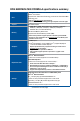
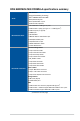
ROG MAXIMUS Z690 FORMULA specifications summary Intel® Socket LGA1700 for 12th Gen Intel® Core™, Pentium® Gold and Celeron® Processors* CPU Supports Intel® Turbo Boost Technology 2.0 and Intel® Turbo Boost Max Technology 3.0** * Refer to www.asus.com for CPU support list. ** Intel® Turbo Boost Max Technology 3.0 support depends on the CPU types. Chipset Intel® Z690 Chipset 4 x DIMM, Max.
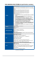
ROG MAXIMUS Z690 FORMULA specifications summary Intel® Z690 Chipset** M.2_2 slot (Key M), type 2242/2260/2280 (supports PCIe 3.0 x4 mode) M.2_3 slot (Key M), type 2242/2260/2280 (supports PCIe 4.0 x4 & SATA modes) Hyper M.2_1 slot (Key M) via ROG Hyper M.2 card, type 2242/2260/2280/22110 (suppports PCIe 4.0 x4 mode)*** Hyper M.2_2 slot (Key M) via ROG Hyper M.2 card, type 2242/2260/2280/22110 (suppports PCIe 4.
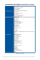
ROG MAXIMUS Z690 FORMULA specifications summary Audio Features: - SupremeFX Shielding Technology Audio - ESS® SABRE9018Q2C DAC/AMP - Gold-plated audio jacks - Rear optical S/PDIF out port - Premium audio capacitors 2 x Thunderbolt™ 4 USB Type-C® ports 7 x USB 3.2 Gen 2 port(s) (6 x Type-A + 1 x USB Type-C®) 3 x USB 2.
ROG MAXIMUS Z690 FORMULA specifications summary Miscellaneous 3 x Addressable Gen 2 headers 1 x AURA RGB header 1 x FlexKey button Internal I/O connectors 1 x 12-1 pin Front Panel Audio header (AAFP) 1 x ReTry button 1 x SPI TPM header (14-1pin) 1 x Start button 1 x 10⁻¹ pin System Panel header 1 x Thermal Sensor header Extreme OC Kit - FlexKey button - ReTry button - Start button Extreme Engine Digi+ - 10K Black Metallic Capacitors - MicroFine Alloy Choke ASUS Q-Design - M.
ROG MAXIMUS Z690 FORMULA specifications summary Front Panel USB 3.2 Gen 2x2 with Quick Charge 4+ Support - Support: up to 60W charging* - Output: 5/9/15/20V max. 3A, PPS:3.3–21V max. 3A Special Features - Compatible with QC 4.0/3.0/2.0, PD3.0 and PPS * To support 60W, please install the power cable to 6-pin PCIe Graphics Card connector or can only support 27W. ASUS HYDRANODE - 3 x Chassis fan support* (CHA_FAN1P,CHA_FAN2P,CHA_FAN3P)* * Visit ASUS Website for the latest compatibility list.
ROG MAXIMUS Z690 FORMULA specifications summary BIOS 256 Mb Flash ROM, UEFI AMI BIOS Manageability WOL by PME, PXE Operating System Form Factor xii Windows® 11 64-bit Windows® 10 64-bit ATX Form Factor 12 inch x 9.6 inch ( 30.5 cm x 24.4 cm ) • Specifications are subject to change without notice. Please refer to the ASUS website for the latest specifications.
Package contents Check your motherboard package for the following items. Motherboard 1 x ROG MAXIMUS Z690 FORMULA motherboard 1 x ARGB RGB extension cable 1 x RGB extension cable Cables 2 x ROG weave SATA 6G cables 4 x SATA 6Gb/s cables ROG HYPER M.2 CARD 1 x ROG Hyper M.2 Card with heatsink 2 x M.2 screw packages for ROG Hyper M.2 Card 1 x ASUS Wi-Fi moving antennas 1 x M.2 Rubber Package(s) 1 x Q-connector 1 x M.2 Q-Latch package(s) Miscellaneous 2 x M.2 Q-Latch packages for M.2 backplate 1 x M.
Installation tools and components Phillips (cross) screwdriver PC chassis Power supply unit Intel® LGA 1700 CPU Intel® LGA 1700 compatible CPU Fan DDR5 DIMM SATA hard disk drive SATA optical disc drive (optional) Graphics card (optional) M.2 SSD module (optional) 1 Bag of screws The tools and components in the table above are not included in the motherboard package.
Product Introduction Product Introduction 1.1 Before you proceed 1 Chapter 1 Chapter 1: Take note of the following precautions before you install motherboard components or change any motherboard settings. • Unplug the power cord from the wall socket before touching any component. • Before handling components, use a grounded wrist strap or touch a safely grounded object or a metal object, such as the power supply case, to avoid damaging them due to static electricity.
1.
ROG MAXIMUS Z690 FORMULA Page 1-4 1-5 1-7 1-9 1-10 1-11 1-12 1-13 1-14 1-14 1-15 1-16 1-17 1-18 1-19 1-19 1-20 1-21 1-22 1-23 1-24 1-25 1-25 1-26 Chapter 1 Layout contents 1. CPU socket 2. DIMM slots 3. Expansion slots 4. Fan and Pump headers 5. Liquid Cooling System headers 6. Power connectors 7. M.2 Slot 8. SATA 6Gb/s port 9. USB 3.2 Gen 2x2 Type-C® Front Panel connector 10. USB 3.2 Gen 1 header 11. USB 2.0 header 12. Addressable Gen 2 header 13. AURA RGB header 14. FlexKey button 15.
1. CPU socket The motherboard comes with a LGA1700 socket designed for 12th Gen Intel® Core™, Pentium® Gold and Celeron® Processors. Chapter 1 1-4 • Ensure that you install the correct CPU designed for LGA1700 socket only. DO NOT install a CPU designed for other sockets on the LGA1700 socket. • The CPU fits in only one correct orientation. DO NOT force the CPU into the socket to prevent bending the connectors on the socket and damaging the CPU.
2. DIMM slots The motherboard comes with Dual Inline Memory Modules (DIMM) slots designed for DDR5 (Double Data Rate 5) memory modules. Chapter 1 A DDR5 memory module is notched differently from a DDR, DDR2, DDR3, or DDR4 module. DO NOT install a DDR, DDR2, DDR3, or DDR4 memory module to the DDR5 slot.
Memory configurations You may install 8GB, 16GB, and 32GB unbuffered and non‑ECC DDR5 DIMMs into the DIMM sockets. Chapter 1 You may install varying memory sizes in Channel A and Channel B. The system maps the total size of the lower-sized channel for the dual-channel configuration. Any excess memory from the higher-sized channel is then mapped for single-channel operation.
3. Expansion slots Chapter 1 Unplug the power cord before adding or removing expansion cards. Failure to do so may cause you physical injury and damage motherboard components. Please refer to the following table for the recommended Hyper M.2 configuration.
PCIe bifurcation & M.2 settings in PCIe x16 slots for ROG Hyper M.2 Card Slot Description Chapter 1 1-8 Quantity of identifiable M.2 SSD (pcs) Situation for ROG Hyper M.2 Card Hyper M.2_1 Hyper M.2_2 1 PCIEX16(G5)_1 PCIe 4.0 x4 - 2 PCIEX16(G5)_2 PCIe 5.0 x4/ PCIe 4.0 x4 - 3 PCIEX16(G4) PCIe 4.0 x4 PCIe 4.0 x4 • The ROG Hyper M.2 card is bundled as an accessory. • Ensure to enable the ROG Hyper M.2 card under BIOS settings. • When ROG Hyper M.2 card is installed on PCIEX16(G5)_1, Hyper M.
4. Fan and Pump headers Chapter 1 The Fan and Pump headers allow you to connect fans or pumps to cool the system. When an ASUS HYDRANODE fan is connected to a ASUS HYDRANODE fan connector, the ASUS HYDRANODE function will be available. • DO NOT forget to connect the fan cables to the fan headers. Insufficient air flow inside the system may damage the motherboard components. These are not jumpers! Do not place jumper caps on the fan headers! • Ensure the cable is fully inserted into the header.
5. Liquid Cooling System headers The Liquid Cooling System headers allow you to connect sensors to monitor the temperature and flow rate of your liquid cooling system. You can manually adjust the fans and water pump to optimize the thermal efficiency of your liquid cooling system.
6. Power connectors Chapter 1 These Power connectors allow you to connect your motherboard to a power supply. The power supply plugs are designed to fit in only one orientation, find the proper orientation and push down firmly until the power supply plugs are fully inserted. Ensure to connect the 8-pin power plug, or connect both 8-pin power plugs. • We recommend that you use a PSU with a higher power output when configuring a system with more power-consuming devices.
7. M.2 slot The M.2 slot allows you to install M.2 devices such as M.2 SSD modules. Chapter 1 • Intel® 12th Gen Processors: - M.2_1 supports PCIE 4.0 x4 mode M Key design and type 2242 / 2260 / 2280 / 22110 storage devices. • Intel® Z690 Chipset: - M.2_2 supports PCIE 3.0 x4 mode M Key design and type 2242 / 2260 / 2280 storage devices. - M.2_3 supports PCIE 4.0 x4 and SATA modes M Key design and type 2242 / 2260 / 2280 storage devices.
8. SATA 6Gb/s port Chapter 1 The SATA 6Gb/s port allows you to connect SATA devices such as optical disc drives and hard disk drives via a SATA cable. • If you installed SATA storage devices to the SATA6G_1-4 ports, you can create a RAID 0, 1, 5, and 10 configuration with the Intel® Rapid Storage Technology through the onboard Intel® Z690 chipset. • RAID configuration and boot drives are not supported on the SATA6G_E1-2 ports. Before creating a RAID set, refer to the RAID Configuration Guide.
9. USB 3.2 Gen 2x2 Type-C® Front Panel connector Chapter 1 The USB 3.2 Gen 2x2 Type-C® connector allows you to connect a USB 3.2 Gen 2x2 Type-C® module for an additional USB 3.2 Gen 2x2 Type-C® port on the front panel. The USB 3.2 Gen 2x2 Type-C® connector provides data transfer speeds of up to 20 Gb/s. The USB 3.2 Gen 2x2 Type-C® module is purchased separately. 10. USB 3.2 Gen 1 header The USB 3.2 Gen 1 header allows you to connect a USB 3.2 Gen 1 module for additional USB 3.2 Gen 1 ports. The USB 3.
11. USB 2.0 header Chapter 1 The USB 2.0 header allows you to connect a USB module for additional USB 2.0 ports. The USB 2.0 header provides data transfer speeds of up to 480 Mb/s connection speed. DO NOT connect a 1394 cable to the USB connectors. Doing so will damage the motherboard! The USB 2.0 module is purchased separately.
12. Addressable Gen2 header The Addressable Gen2 header allows you to connect individually addressable RGB WS2812B LED strips or WS2812B based LED strips. Chapter 1 The Addressable Gen2 header supports WS2812B addressable RGB LED strips (5V/ Data/Ground), with a maximum power rating of 3A (5V), and the addressable headers on this board can handle a combined maximum of 500 LEDs.
13. AURA RGB header Chapter 1 The AURA RGB header allows you to connect RGB LED strips. The AURA RGB header supports 5050 RGB multi-color LED strips (12V/G/R/B), with a maximum power rating of 3A (12V). Before you install or remove any component, ensure that the power supply is switched off or the power cord is detached from the power supply. Failure to do so may cause severe damage to the motherboard, peripherals, or components. • Actual lighting and color will vary with LED strip.
14. FlexKey button (Reset) Press the FlexKey button to reboot the system. You may also configure the button and assign a quick access feature such as activating Safe Boot or turning Aura lighting on or off to the button. Chapter 1 This button set to [Reset] by default. You can assign a different function to this button in the BIOS settings.
15. Front Panel Audio header Chapter 1 The Front Panel Audio header is for a chassis-mounted front panel audio I/O module that supports HD Audio. Connect one end of the front panel audio I/O module cable to this header. We recommend that you connect a high-definition front panel audio module to this connector to avail of the motherboard’s high-definition audio capability. The HYDRANODE pins are reserved for ASUS HYDRANODE devices.
16. ReTry button Chapter 1 The ReTry button is specially designed for overclockers and is most useful during the booting process where the Reset button is rendered useless. Press this button to force the system to reboot while retaining the same settings to be retried in quick succession to achieve a successful POST. 17. Start button Press the Start button to power up the system, or put the system into sleep or soft-off mode (depending on the operating system settings).
18. System Panel header Chapter 1 The System Panel header supports several chassis-mounted functions. • System Power LED header (PLED) The 2-pin header allows you to connect the System Power LED. The System Power LED lights up when the system is connected to a power source, or when you turn on the system power, and blinks when the system is in sleep mode. • Storage Device Activity LED header (HDLED) The 2-pin header allows you to connect the Storage Device Activity LED.
19. Thermal Sensor header Chapter 1 The Thermal Sensor header allows you to connect a sensor to monitor the temperature of the devices and the critical components inside the motherboard. Connect the thermal sensor and place it on the device or the motherboard’s component to detect its temperature. The thermal sensor is purchased separately.
20. TPM header Chapter 1 The TPM header allows you to connect a TPM module, which securely stores keys, digital certificates, passwords, and data. A TPM system also helps enhance network security, protect digital identities, and ensures platform integrity. The TPM module is purchased separately.
21. Q-Code LED The Q-Code LED design provides you with a 2-digit error code that displays the system status. Chapter 1 1-24 • The Q-Code LEDs provide the most probable cause of an error code as a starting point for troubleshooting. The actual cause may vary from case to case. • Please refer to the Q-Code table in the Appendix section for more details.
22. Q-LEDs Chapter 1 The Q-LEDs check key components (CPU, DRAM, VGA, and booting devices) during the motherboard booting process. If an error is found, the critical component’s LED stays lit up until the problem is solved. The Q-LEDs provide the most probable cause of an error code as a starting point for troubleshooting. The actual cause may vary from case to case. 23.
24. 8-pin Power Plug LED The 8-pin Power Plug LED lights up to indicate that the 8-pin power plug is not connected.
Chapter 2: Basic Installation Basic Installation 2.1 Building your PC system 2 The diagrams in this section are for reference only. The motherboard layout may vary with models, but the installation steps are the same for all models. CPU installation • Ensure that you install the correct CPU designed for LGA1700 socket only. DO NOT install a CPU designed for LGA1155, LGA1156, LGA1151, and LGA1200 sockets on the LGA1700 socket.
Chapter 2 Ensure to remove the CPU Socket lever protector on the lever latch before locking the lever latch under the retention tab. Failure to do so may cause damages to your system when installing the cooling system.
2.1.2 Cooling system installation • Apply Thermal Interface Material to the CPU cooling system and CPU before you install the cooling system, if necessary. • Ensure to remove the CPU Socket lever protector on the lever latch before installing the cooling system, failure to do so may cause damages to your system.
• We recommend using a LGA1700 compatible cooling system on an Intel® 600 series motherboard. • Additional holes for LGA1200 compatible cooling systems are also available on ASUS’ Intel® 600 series motherboards, however, we still strongly advise consulting with your cooling system vendor or manufacturer on the compatibility and functionality of the cooling system. • Push-pin type LGA1200 compatible cooling systems cannot be installed to this motherboard.
To install an AIO cooler We recommend using a LGA1700 compatible cooling system when installing a cooling system to an Intel® 600 series motherboard. • Additional holes for LGA1200 compatible cooling systems are also available on ASUS’ Intel® 600 series motherboards, however, we still strongly advise consulting with your cooling system vendor or manufacturer on the compatibility and functionality of the cooling system.
2.1.
2.1.4 M.2 installation Supported M.2 type varies per motherboard. • The illustrations only show the installation steps for a single M.2 slot, the steps are the same for the other M.2 slots if you wish to install an M.2 to another M.2 slot. • Use a Phillips screwdriver when removing or installing the screws or screw stands mentioned in this section. • If the thermal pad on the M.2 heatsink becomes damaged and needs to replaced, we recommend replacing it with a thermal pad with a thickness of 1.25mm.
2. Gently lift and swivel the heatsink away from the M.2 slot. The heatsink has a cable connected to the motherboard, ensure not to pull on the heatsink as this may result in damages to the cable.
3. Install your M.2 to your M.2 slot. The steps may differ between installing M.2 of different lengths, please refer to the different types and their installation steps below: For 22110 length A. Remove the pre-installed M.2 Q-latch at the 2280 length screw hole by rotating the handle counterclockwise then pushing it towards the M.2 slot and removing it from the latch hole. B. Remove the plastic film from the thermal pad. C. Rotate and adjust the M.
For 2280 length A. Rotate and adjust the M.2 Q-latch at the 2280 position so that the handle points away from the M.2 slot. B. Remove the plastic film from the thermal pad. C. Install your M.2 to the M.2 slot. D. Rotate the M.2 Q-Latch clockwise to secure the M.2 in place.
For 2242 and 2260 length A. Remove the pre-installed M.2 Q-latch at the 2280 length screw hole by rotating the handle counterclockwise then pushing it towards the M.2 slot and removing it from the latch hole. B. Remove the plastic film from the thermal pad. C. Remove the plastic film and thermal pad of the M.2 length screw hole you wish to install your M.2 to, then install the M.2 Q-latch. D. Rotate and adjust the M.2 Q-latch so that the handle points away from the M.2 slot. E. Install your M.2 to the M.
4. Remove the plastic film from the thermal pads on the bottom of the heatsink. If the thermal pad on the M.2 heatsink becomes damaged and needs to replaced, we recommend replacing it with a thermal pad with a thickness of 1.25mm. 5. Replace the heatsink. 6. Secure the heatsinks using the screws on the heatsink. Chapter 2 For M.2_2 and M.2_3 2-12 1. Loosen the screws from the M.2 heatsink. 2. Lift and remove the heatsink.
3. Install your M.2 to your M.2 slot. The steps may differ between installing M.2 of different lengths, please refer to the different types and their installation steps below: • To install an M.2 to M.2_2 slot For 2280 length A. (optional) Install the bundled M.2 rubber pad if you are installing a single sided M.2 storage device. DO NOT install the bundled M.2 rubber pads when installing a double-sided M.2 storage device. The rubber pad installed by default is compatible with double sided M.
For 2242, 2260 length A. (optional) Remove the M.2 rubber pad. Follow this step only if you wish to install an M.2 to type 2242. B. Install the M.2 Q-Latch to the M.2 length screw hole you wish to install your M.2 to. C. Rotate and adjust the M.2 Q-latch so that the handle points away from the M.2 slot. D. Install your M.2 to the M.2 slot. E. Rotate the M.2 Q-Latch clockwise to secure the M.2 in place.
• To install an M.2 to M.2_3 slot For 2280 length A. Remove the plastic film from the thermal pad. B. Rotate and adjust the M.2 Q-latch at the 2280 position so that the handle points away from the M.2 slot. C. Install your M.2 to the M.2 slot. Chapter 2 D. Rotate the M.2 Q-Latch clockwise to secure the M.2 in place.
For 2242 and 2260 length A. Remove the plastic film from the thermal pad. B. Remove the plastic film and thermal pad of the M.2 length screw hole you wish to install your M.2 to, then install the M.2 Q-latch. C. Rotate and adjust the M.2 Q-latch so that the handle points away from the M.2 slot. D. Install your M.2 to the M.2 slot. E. Rotate the M.2 Q-Latch clockwise to secure the M.2 in place.
4. Remove the plastic film from the thermal pads on the bottom of the heatsinks. If the thermal pad on the M.2 heatsink becomes damaged and needs to replaced, we recommend replacing it with a thermal pad with a thickness of 1.25mm. Replace the heatsinks. 6. Secure the heatsinks using the screws on the heatsink. Chapter 2 5.
2.1.5 Motherboard installation Place the motherboard into the chassis, ensuring that its rear I/O ports are aligned to the chassis’ rear I/O panel. 2. Place eight (8) screws into the holes indicated by circles to secure the motherboard to the chassis. Chapter 2 1. DO NOT over tighten the screws! Doing so can damage the motherboard.
ATX power connection Chapter 2 2.1.6 OR AND Ensure to connect the 8-pin power plug or both 8-pin power plugs.
Chapter 2 The PD_12V_PWR connector provides additional power for your PCIe X16 slots. To support 60W, please install the power cable to the 6-pin PCIe Graphics Card connector (PD_12V_PWR) else only 27W will be supported.
2.1.
2.1.8 Front I/O connector To install ASUS Q-Connector To install USB 3.2 Gen 2x2 Type-C® connector USB 3.2 Gen 2x2 Type-C® Chapter 2 This connector will only fit in one orientation. Push the connector until it clicks into place. To install USB 3.2 Gen 1 connector To install USB 2.0 connector USB 2.0 USB 3.
2.1.
To install ROG HYPER M.2 Card Remove the four (4) cover screws that secure the cover to the ROG HYPER M.2 card, then remove the cover and set it aside. 2. Peel the plastic films off the thermal pads by the M.2 slots. 3. Secure the stand screws onto the ROG HYPER M.2 card. Chapter 2 1.
Install the M.2 storage devices into the onboard M.2 slots (A), then secure the M.2 storage devices with the bundled screws (B). • When ROG Hyper M.2 card is installed on PCIEX16(G5)_1 or PCIEX16(G5)_2, Hyper M.2_2 slot will be disabled. When ROG Hyper M.2 card is installed on PCIEX16(G4), Hyper M.2_1 and Hyper M.2_2 slots can support PCIe 4.0 x4 mode • When ROG Hyper M.2 card is installed on PCIEX16(G5)_1, Hyper M.2_1 slot can support PCIe 4.0 x4 mode. When ROG Hyper M.
6. Enter the BIOS Setup during POST to configure your BIOS settings. For more information on configuring your RAID sets, please refer to the RAID Configuration Guide which you can find at https://www.asus.com/support, or by scanning the QR code.
Using the PCIe Slot Q-Release The PCIEX16(G5)_1 slot comes with a PCIe Slot Q-Release button allowing you to easily remove an expansion card installed to this PCIe slot, even when the expansion card may be blocking the PCIe push-latch, such as a graphics card. Before installing an expansion card: Pressing the PCIe Slot Q-Release button before installing an expansion card to this slot will ensure the PCIe push-latch is completely pushed down before installation.
2.1.10 Wi-Fi moving antenna installation Installing the ASUS Wi-Fi moving antenna Connect the bundled ASUS Wi-Fi moving antenna connector to the Wi-Fi ports at the back of the chassis. Chapter 2 • Ensure that the ASUS Wi-Fi moving antenna is securely installed to the Wi-Fi ports. • Ensure that the antenna is at least 20 cm away from all persons. The illustration above is for reference only.
2.2 BIOS update utility BIOS FlashBack™ BIOS FlashBack™ allows you to easily update the BIOS without entering the existing BIOS or operating system. To use BIOS FlashBack™: 1. Insert a USB storage device to the BIOS FlashBack™ port. 2. Visit https://www.asus.com/support/ and download the latest BIOS version for this motherboard. 3. Manually rename the file as MZ690F.CAP, or launch the BIOSRenamer.exe application to automatically rename the file, then copy it to your USB storage device.
For more information on using the BIOS FlashBack™ feature, please refer to https://www.asus.com/support/, or by scanning the QR code below.
Motherboard rear and audio connections 2.3.1 Rear I/O connection Chapter 2 2.3 Rear panel connectors 2. 3. 4. 5. 6. 7. 8. 9. 10. Clear CMOS button (CLR_CMOS). Press this button to clear the BIOS setup information only when the systems hangs due to overclocking. USB 2.0 ports E5 and E6 Marvell® AQtion 10Gb Ethernet port* USB 3.2 Gen 2 Type-A ports 1 and 2 USB 3.2 Gen 2 Type-A ports 4, 5, 6, and P7 BIOS FlashBack™ button HDMI® port Thunderbolt™ 4 USB Type-C® port E1 USB 2.
* Marvell® AQtion 10Gb Ethernet port LED indications Activity Link LED Speed LED Status Description Status Description OFF GREEN BLINKING No link Linked Data activity OFF GREEN No link 10 Gbps 5 Gbps/ 2.5 Gbps/ 1Gbps/ 100 Mbps connection ORANGE ACT/LINK LED SPEED LED LAN port ** Audio 2, 4, 5.1 or 7.1-channel configuration 4-channel 5.1-channel 7.
Connect to Stereo Speakers Chapter 2 Connect to 2-channel Speakers Connect to 4-channel Speakers ROG MAXIMUS Z690 FORMULA 2-33
Connect to 5.1-channel Speakers Chapter 2 Connect to 7.
2.4 Starting up for the first time 1. After making all the connections, replace the system case cover. 2. Ensure that all switches are off. 3. Connect the power cord to the power connector at the back of the system chassis. 4. Connect the power cord to a power outlet that is equipped with a surge protector. 5. Turn on the devices in the following order: Monitor b. External storage devices (starting with the last device on the chain) c.
Chapter 2 2-36 Chapter 2: Basic Installation
Chapter 3: BIOS and RAID Support BIOS and RAID Support 3 For more details on BIOS and RAID configurations, please refer to www.asus.com/ support. 3.1 Knowing BIOS The new ASUS UEFI BIOS is a Unified Extensible Interface that complies with UEFI architecture, offering a user-friendly interface that goes beyond the traditional keyboardonly BIOS controls to enable a more flexible and convenient mouse input. You can easily navigate the new UEFI BIOS with the same smoothness as your operating system.
3.2 BIOS setup program Use the BIOS Setup to update the BIOS or configure its parameters. The BIOS screen include navigation keys and brief onscreen help to guide you in using the BIOS Setup program. Entering BIOS at startup To enter BIOS Setup at startup, press or during the Power-On Self Test (POST). If you do not press or , POST continues with its routines. Entering BIOS Setup after POST To enter BIOS Setup after POST: • Press ++ simultaneously.
3.3 ASUS EZ Flash 3 The ASUS EZ Flash 3 feature allows you to update the BIOS without using an OS‑based utility. Ensure to load the BIOS default settings to ensure system compatibility and stability. Select the Load Optimized Defaults item under the Exit menu or press hotkey . To update the BIOS: • This function can support devices such as a USB flash disk with FAT 32/16 format and single partition only.
3.4 ASUS CrashFree BIOS 3 The ASUS CrashFree BIOS 3 utility is an auto recovery tool that allows you to restore the BIOS file when it fails or gets corrupted during the updating process. You can restore a corrupted BIOS file using a USB flash drive that contains the BIOS file. Recovering the BIOS 1. Download the latest BIOS version for this motherboard from whttps://www.asus.com/support/. 2. Rename the BIOS file as ASUS.CAP or MZ690F.CAP and copy the renamed BIOS file to a USB flash drive. 3.
3.5 RAID configurations The motherboard comes with the Intel® Rapid Storage Technology that supports NVMe RAID 0/1/5 and SATA RAID 0/1/5/10 configurations. For more information on configuring your RAID sets, please refer to the RAID Configuration Guide which you can find at https://www.asus.com/support, or by scanning the QR code. RAID definitions RAID 0 (Data striping) optimizes two identical hard disk drives to read and write data in parallel, interleaved stacks.
Chapter 3 3-6 Chapter 3: BIOS Setup
Appendix Appendix Code 00 01 02 03 04 06 Description Not used Power on. Reset type detection (soft/hard).
Q-Code table Code Appendix E0 E1 E2 E3 E4 – E7 E8 E9 EA EB EC – EF F0 F1 F2 F3 F4 F5 – F7 F8 F9 FA FB – FF 60 61 62 63 – 67 68 69 Description S3 Resume is stared (S3 Resume PPI is called by the DXE IPL) S3 Boot Script execution Video repost OS S3 wake vector call Reserved for future AMI progress codes S3 Resume Failed S3 Resume PPI not Found S3 Resume Boot Script Error S3 OS Wake Error Reserved for future AMI error codes Recovery condition triggered by firmware (Auto recovery) Recovery condition triggere
Q-Code table Description Boot Device Selection (BDS) phase is started Driver connecting is started PCI Bus initialization is started PCI Bus Hot Plug Controller Initialization PCI Bus Enumeration PCI Bus Request Resources PCI Bus Assign Resources Console Output devices connect Console input devices connect Super IO Initialization USB initialization is started USB Reset USB Detect USB Enable Reserved for future AMI codes IDE initialization is started IDE Reset IDE Detect IDE Enable SCSI initialization is sta
Q-Code table Code B4 B5 B6 B7 B8– BF D0 D1 D2 D3 D4 D5 D6 D7 D8 D9 DA DB DC Description USB hot plug PCI bus hot plug Clean-up of NVRAM Configuration Reset (reset of NVRAM settings) Reserved for future AMI codes CPU initialization error System Agent initialization error PCH initialization error Some of the Architectural Protocols are not available PCI resource allocation error.
Notices FCC Compliance Information Responsible Party: Asus Computer International Address: 48720 Kato Rd., Fremont, CA 94538, USA Phone / Fax No: (510)739-3777 / (510)608-4555 This device complies with part 15 of the FCC Rules. Operation is subject to the following two conditions: (1) This device may not cause harmful interference, and (2) this device must accept any interference received, including interference that may cause undesired operation.
Compliance Statement of Innovation, Science and Economic Development Canada (ISED) This device complies with Innovation, Science and Economic Development Canada licence exempt RSS standard(s). Operation is subject to the following two conditions: (1) this device may not cause interference, and (2) this device must accept any interference, including interference that may cause undesired operation of the device.
Google™ License Terms Copyright© 2021 Google Inc. All Rights Reserved. Licensed under the Apache License, Version 2.0 (the “License”); you may not use this file except in compliance with the License. You may obtain a copy of the License at: http://www.apache.org/licenses/LICENSE-2.0 Unless required by applicable law or agreed to in writing, software distributed under the License is distributed on an “AS IS” BASIS, WITHOUT WARRANTIES OR CONDITIONS OF ANY KIND, either express or implied.
Declaration of compliance for product environmental regulation ASUS follows the green design concept to design and manufacture our products, and makes sure that each stage of the product life cycle of ASUS product is in line with global environmental regulations. In addition, ASUS disclose the relevant information based on regulation requirements. Please refer to http://csr.asus.com/Compliance.
Simplified UKCA Declaration of Conformity ASUSTek Computer Inc. hereby declares that this device is in compliance with the essential requirements and other relevant provisions of The Radio Equipment Regulations 2017 (S.I. 2017/1206). Full text of UKCA declaration of conformity is available at https://www.asus.com/support/.
Appendix Simplified EU Declaration of Conformity ASUSTek Computer Inc. hereby declares that this device is in compliance with the essential requirements and other relevant provisions of Directive 2014/53/EU. Full text of EU declaration of conformity is available at https://www.asus.com/support/ The WiFi operating in the band 5150-5350MHz shall be restricted to indoor use for countries listed in the table below: Déclaration simplifiée de conformité de l’UE ASUSTek Computer Inc.
ประกาศเกี่ยวกับความสอดคล้องของสหภาพยุโรปแบบย่อ ASUSTek Computer Inc. ขอประกาศในที่่นี้้ � ว่� า่ อุุปกรณ์์นี้้มี � ค ี วามสอดคล้ ้อง กัับความ ต้ ้องการที่่จำ� ำ�เป็็ นและเงื่่อ � นไขที่่เ� กี่่ย � วข้ ้องอื่่น � ๆ ของบทบััญญััติข้ ิ ้อกำำ�หนด 2014/53/EU เนื้้�อหาที่่ส � มบููรณ์์ของประกาศความสอดคล้ ้องกัับ EU มีีอยู่่�ที่ ่� https://www.asus.
Warranty EN: ASUS Guarantee Information • ASUS offers a voluntary manufacturer’s Commercial Guarantee. • ASUS reserves the right to interpret the provisions of the ASUS Commercial Guarantee. • This ASUS Commercial Guarantee is provided independently and in addition to the statutory Legal Guarantee and in no way affects or limits the rights under the Legal Guarantee. CR: Informacije o ASUS jamstvu • ASUS dragovoljno nudi komercijalno proizvođačko jamstvo.
ROG MAXIMUS Z690 FORMULA SW: ASUS garantiinformation • ASUS erbjuder en frivillig kommersiell tillverkningsgaranti. • ASUS förbehåller sig rätten att tolka bestämmelserna i ASUS kommersiella garanti. • Denna kommersiella garanti från ASUS tillhandahålles separat och som tillägg till den lagstadgade garantin, och påverkar eller begränsar på intet sätts rättigheterna under den lagstadgade garantin. För all garantiinformation, besök https://www.asus.com/se/support/.
ASUS contact information ASUSTeK COMPUTER INC. Address: 1F., No. 15, Lide Rd., Beitou Dist., Taipei City 112, Taiwan ASUS COMPUTER INTERNATIONAL (America) Address: 48720 Kato Rd., Fremont, CA 94538, USA ASUS COMPUTER GmbH (Germany and Austria) Address: Harkortstrasse 21-23, 40880 Ratingen, Germany ASUSTeK (UK) LIMITED Address: 1st Floor, Sackville House, 143-149 Fenchurch Street, London, EC3M 6BL, England, United Kingdom Service and Support Visit our multi-language website at https://www.asus.