使用手冊 Motherboard ROG STRIX X570-E GAMING WIFI II
T19182 第二版 2021 年 9 月 版權說明 © ASUSTeK Computer Inc. All rights reserved.
目錄內容 安全性須知..........................................................................................................................................v 限用物質名稱及含量列表............................................................................................................ vi 射頻(RF)設備須知..................................................................................................................... vi 關於這本使用手冊....................................................................................................
附錄 Q-Code 表........................................................................................................................................A-1 Notices ............................................................................................................................................A-5 華碩的連絡資訊............................................................................................................................A-6 服務與支援.....................................................................
安全性須知 電氣方面的安全性 • 為避免可能的電擊造成嚴重損害,在搬動電腦主機之前,請先將電腦電源線暫 時從電源插槽中拔掉。 • 當您要加入硬體裝置到系統中時,請務必先連接該裝置的訊號線,然後再連接 電源線。可能的話,在安裝硬體裝置之前先拔掉電腦的電源供應器電源線。 • 當您要從主機板連接或拔除任何的訊號線之前,請確定所有的電源線已事先拔 掉。 • 在使用介面卡或擴充卡之前,我們建議您可以先尋求專業人士的協助。這些裝 置有可能會干擾接地的迴路。 • 請確定電源供應器的電壓設定已調整到本國/本區域所使用的電壓標準值。若您 不確定您所屬區域的供應電壓值為何,請就近詢問當地的電力公司人員。 • 如果電源供應器已損壞,請不要嘗試自行修復。請將之交給專業技術服務人員 或經銷商來處理。 操作方面的安全性 • 在您安裝主機板以及加入硬體裝置之前,請務必詳加閱讀本手冊所提供的相關 資訊。 • 在使用產品之前,請確定所有的排線、電源線都已正確地連接好。若您發現有 任何重大的瑕疵,請儘速聯絡您的經銷商。 • 為避免發生電氣短路情形,請務必將所有沒用到的螺絲、迴紋針及其他零件收 好,不要遺留在主機
限用物質名稱及含量列表 限用物質及其化學符號 單元 六價鉻 多溴聯苯 多溴二苯醚 (PBB) (PBDE) (Cr+6) 鉛 (Pb) 汞 (Hg) 鎘 (Cd) 印刷電路板 ─ ○ ○ ○ ○ ○ 電子組件 ─ ○ ○ ○ ○ ○ 連接器 ─ ○ ○ ○ ○ ○ 其他及其配件 ─ ○ ○ ○ ○ ○ 備考 1. "○" 係指該項限用物質之百分比含量未超出百分比含量基準值。 備考 2.
哪裡可以找到更多資訊 您可以經由下面所提供的兩個管道來獲得您所使用的華碩產品資訊以及軟硬體 的升級資訊等。 1. 華碩網站 您可以到 https://www.asus.com/tw/ 華碩電腦全球資訊網站取得所有關於華 碩軟硬體產品的各項資訊。台灣以外的華碩網址請參考說明書後面的聯絡資訊。 2. 其他文件 在您的產品包裝盒中除了本手冊所列舉的標準配件之外,也有可能會夾帶 有其他的文件,譬如經銷商所附的產品保證單據等。 提示符號 為了能夠確保您正確地完成主機板設定,請務必注意下面這些會在本手冊中出現 的標示符號所代表的特殊含意。 小心: 提 醒您在進行某一項工作時要注意勿傷害到電腦主機板元件與注 意您自身的安全。 重要: 此 符號表示您必須要遵照手冊所描述之方式完成一項或多項軟硬 體的安裝或設定。 注意: 提供有助於完成某項工作的訣竅和其他額外的資訊。 服務據點查詢 您可以至 https://www.asus.
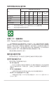
ROG STRIX X570-E GAMING WIFI II 規格列表 中央處理器 AMD Ryzen™ 5000、3000 與 2000 系列 / 5000、4000、3000 與 2000 G 系列處理器* 晶片組 AMD X570 晶片組 * 請瀏覽華碩網站 https://www.asus.
ROG STRIX X570-E GAMING WIFI II 規格列表 AMD Ryzen™ 5000 G 系列 / 4000 G 系列 / 3000 G 系列 / 2000 G 系列 / 2000 系列處理器 - M.2_1 插槽(Key M),支援 2242/2260/2280/22110 類型儲 存裝置(支援 PCIe 3.0 x4 與 SATA 模式) 儲存媒體連接槽 AMD X570 晶片組 - M.2_2 插槽(Key M),支援 2242/2260/2280/22110 類型 儲存裝置(支援 PCIe 4.0 x4 與 SATA 模式) - 8 x SATA 6.0 Gb/s 連接埠 - 支援 RAID 0、RAID 1、RAID 10 1 x Realtek 2.5Gb 網路 網路功能 1 x Intel® 1Gb 網路 LANGuard 網路安全防護 ROG GameFirst 技術 Wi-Fi 6E - 2 x 2 Wi-Fi 6E (802.11 a/b/g/n/ac/ax) 無線與藍牙 - 支援 2.4/5/6GHz 頻帶* Bluetooth v5.
ROG STRIX X570-E GAMING WIFI II 規格列表 8 x USB 3.2 Gen 2 連接埠(7 x Type-A; 1 x USB Type-C®) 1 x DisplayPort 連接埠 1 x HDMI® 連接埠 1 x Wi-Fi 模組 後側面板裝置連接埠 1 x Intel® I211-AT 1Gb 網路控制器 1 x Realtek 2.5Gb 網路連接埠 5 x 鍍金音效插孔 1 x 光纖 S/PDIF 數位音訊輸出連接埠 1 x BIOS Flashback™ 按鈕 風扇與散熱相關 1 x 4-pin 中央處理器風扇接頭 1 x 4-pin 中央處理器選用風扇接頭 1 x 4-pin AIO Pump 接頭 2 x 4-pin 機殼風扇接頭 1 x 4-pin M.2 風扇接頭 1 x W_PUMP+ 插座 電源相關 1 x 24-pin 主電源插槽 1 x 8-pin +12V 電源插槽 1 x 4-pin +12V 電源插槽 儲存相關 2 x M.
ROG STRIX X570-E GAMING WIFI II 規格列表 - Q-LED(處理器 [紅色]、記憶體 [黃色]、顯示卡 [白色]、開機 裝置 [黃綠色]) - Q-Slot 華碩散熱方案 - M.
ROG STRIX X570-E GAMING WIFI II 規格列表 UEFI BIOS 華碩 EZ DIY - 華碩 CrashFree BIOS 3 軟體功能 - 華碩 EZ Flash 3 - 華碩 UEFI BIOS EZ 模式 Dynamic OC Switcher BIOS 256Mb Flash ROM、UEFI AMI BIOS 管理功能 WOL by PXE 支援作業系統 Windows® 11 64-bit、Windows® 10 64-bit 主機板尺寸 ATX 型式,12 x 9.6 吋(30.5 x 24.
包裝內容物 在您拿到本主機板包裝盒之後,請馬上檢查下面所列出的各項標準配件是否齊全。 主機板 1 x ROG STRIX X570-E GAMING WIFI II 主機板 4 x SATA 6Gb/s 排線 排線 1 x 溫度感應線包 1 x 華碩 W-Fi 行動天線 1 x 束線帶包 1 x M.2 橡膠包 1 x M.
建立 PC 系統所需的其他工具與元件 Phillips (十字) 螺絲起子 PC 機殼 電源供應裝置 AMD AM4 中央處理器 AMD AM4 相容處理器風扇 DDR4 記憶體模組 SATA 硬碟 SATA 光碟機(選購) 顯示卡(選購) M.
產品介紹 1.
1.2 主機板結構圖 5 4 17 24.4cm(9.6in) 1 4 2 12 第一章 21 RGB_HEADER1 AIO_PUMP HDMI_DP EATX12V_2 EATX12V_1 CPU_FAN CPU_OPT PLUG_8PIN_PWR CPU DRAM VGA BOOT DIGI +VRM 19 22110 2280 2260 ADD GEN 2_1 2242 11 30.5cm(12in) EATXPWR U32G2_C9 SPI_TPM M.2_1(SOCKET3) AUDIO CHA_FAN1 LED1_CON M.
頁數 中央處理器插槽 1-4 2. 記憶體插槽 1-5 3. 擴充插槽 1-7 4. 風扇與泵接頭 1-8 5. 電源插槽 1-9 6. M.2 插槽 1-10 7. SATA 6Gb/s 連接埠 1-11 8. USB 3.2 Gen 2 Type-C® 前面板連接插槽 1-12 9. USB 3.2 Gen 1 連接插槽 1-12 10. USB 2.0 連接插槽 1-13 11. 可定址 Gen 2 接頭 1-14 12. AURA RGB 燈條接頭 1-15 13. Clear CMOS 接頭 1-16 14. 前面板音效連接排針 1-17 15. 系統控制面板連接排針 1-18 16. 溫度感應線連接排針 1-19 17. TPM 連接排針 1-19 18 1-20 Q-Code 指示燈 19. Q 指示燈 1-20 20. BIOS FlashBack™ 指示燈 1-21 21.
1.
2.
記憶體建議設定 第一章 記憶體設定 您可以任意選擇使用 2GB、4GB、8GB、16GB 與 32GB 的 un-buffered DDR4 記憶 體模組至本主機板的記憶體插槽上。 您可以在通道 A、通道 B 安裝不同容量的記憶體模組。在雙通道設定中, 系統會偵測較低容量通道的記憶體容量。任何在較高容量通道的其他記憶 體容量,會被偵測為單通道模式執行。 • 預設的記憶體運作頻率是依據其 SPD(Serial Presence Detect)。在 預設狀態下,某些記憶體在超頻時的運作頻率可能會較供應商所標示 的數值為低。 • 在全負載或超頻設定下,記憶體可能需要更佳的冷卻系統以維持運作 的穩定。 • 請安裝相同 CAS Latency 的記憶體模組。為求最佳相容性,建議您安 裝同廠牌、相同資料碼(D/C)版本的記憶體模組。請先與供應商確認 並購買正確的記憶體模組。 • 請造訪華碩網站 https://www.asus.
3.
4. 風扇與泵接頭 將風扇電源接頭連接到主機板上的風扇電源插槽,確定每條排線的黑線是連 接到風扇電源插槽上的接地端(GND)。 第一章 C A CPU_FAN B AIO_PUMP C CPU_OPT D CHA_FAN1 GND B FAN PWM FAN IN FAN PWR A D FAN PWM FAN IN FAN PWR F F E G G CHA_FAN2 W_PUMP+ M.
5. 電源插槽 這些電源插槽可讓您將主機板連接到電源供應器。電源供應器所提供的連 接插頭已經過特別設計,只能以一個特定方向插入主機板上的電源插槽。找到 正確的插入方向後,僅需穩穩地將之套進插槽中即可。 B EATX12V_1 PIN 1 GND GND GND GND GND GND PIN 1 C C 第一章 EATX12V_2 +DC_IN +DC_IN B +12V DC +12V DC +12V DC +12V DC A A EATXPWR +3 Volts +12 Volts +12 Volts +5V Standby Power OK GND +5 Volts GND +5 Volts GND +3 Volts +3 Volts GND +5 Volts +5 Volts +5 Volts -5 Volts GND GND GND PSON# GND -12 Volts +3 Volts PIN 1 請務必連接 8-pin 電源插頭。 • 建議您使用與 2.
6. M.2 插槽 (M.2_1、M.2_2) 這些插槽用來安裝 M.2 固態硬碟。 第一章 A B A M.2_1(SOCKET3) M.2_2(SOCKET3) B • AMD Ryzen™ 5000 / 3000 系列處理器: M.2_1 插槽(Key M),支援 2242/2260/2280/22110 類型儲存裝置 (支援 PCIe 4.0 x4 與 SATA 模式) • AMD Ryzen™ 5000 G 系列 / 4000 G 系列 / 3000 G 系列 / 2000 G 系 列 / 2000 系列處理器: M.2_1 插槽(Key M),支援 2242/2260/2280/22110 類型儲存裝置 (支援 PCIe 3.0 x4 與 SATA 模式) • AMD X570 晶片組: M.2_2 插槽(Key M),支援 2242/2260/2280/22110 類型儲存裝置 (支援PCIe 4.0 x4 與 SATA 模式) •M.
7.
8. USB 3.2 Gen 2 Type-C® 前面板連接插槽 這個插槽用來連接 USB 3.2 Gen 2 Type-C® 模組,可擴充 USB 3.2 Gen 2 Type-C® 連接埠。USB 3.2 Gen 2 Type-C® 的資料傳輸率最高可達 10Gb/s。 第一章 U32G2_C9 VBUS TX2+ TX2GND RX2+ RX2GND DD+ CC2 SBU2 SBU1 CC1 VBUS RX1RX1+ GND TX1TX1+ VBUS USB 3.2 Gen 2 Type-C® 模組為選購配備,請另行購買。 9. USB 3.2 Gen 1 連接插槽 這個插槽用來連接 USB 3.2 Gen 1 模組,可在前面板或後側連接埠擴充 USB 3.2 Gen 1 連接埠。USB 3.
10. USB 2.0 連接插槽 第一章 這些插槽用來連接 USB 2.0 模組,可在前面板或後側連接埠擴充 USB 2.0 模組。USB 2.0 的資料傳輸率最高可達 480Mb/s。 A USB_34 USB_12 PIN 1 A B USB+5V USB_P2USB_P2+ GND USB+5V USB_P1USB_P1+ GND NC B 請勿將 1394 排線連接到 USB 插槽上。這麼做可能會導致主機板的損毀! USB 2.
11.
12.
13. Clear CMOS 接頭 這個接頭可讓您清除 CMOS 的 Real Time Clock(RTC)記憶體中的資料。 您可以藉由清除 CMOS RTC 記憶體資料清除存於 CMOS 記憶體中的日期、時間 與系統設定參數。CMOS 中的記憶體資料是主機板內建的鋰電池供電,資料包括 系統設定資訊,像是系統密碼等。 第一章 +3V_BAT GND CLRTC PIN 1 想要清除這些資料,可以依照下列步驟進行: 1. 關閉電腦電源,拔掉電源線; 2. 用一個金屬物體,如螺絲起子,將 CLRTC 接頭的兩個針腳短路。 3. 插上電源線,開啟電腦電源; 4.
14.
15.
16. 溫度感應線連接排針 第一章 此排針用於連接溫度感應線,可以讓您監控主機板重要元件和連接裝置的 溫度。連接溫度感應器排線,然後將感應器放置在這些裝置或主機板的元件上 面,便可進行偵測其溫度。 T_SENSOR GND SENSOR IN PIN 1 溫度感應器為選購配備,請另行購買。 17. TPM 連接排針 這個插座支援可信任安全平台模組(TPM)系統,用來安全地儲存金鑰、 數位認證、密碼和資料。可信任安全平台模組(TPM)系統也用來協助加強網 路安全,保護數位身份,以及確保平台的安全性。 SPI_TPM PIN 1 +1.
18. Q-Code 指示燈 Q-Code 指示燈設計為 2 位元顯示,用來得知系統狀態。 第一章 • Q-Code 指示燈提供最有可能的錯誤原因以幫助找到問題點。實際的 原因將視情況而異。 • 請參考附錄中的 Q-Code 列表來獲得更詳細的資訊。 19.
第一章 20. BIOS FlashBack™ 指示燈 FlashBack™ 指示燈亮或閃爍代表 BIOS FlashBack™ 的狀態。 FLBK_LED 21.
第一章 1-22 第一章:產品介紹
第二章:硬體裝置資訊 硬體裝置資訊 2.1 建立您的電腦系統 2 本章節的圖示僅供參考。主機板的構造可能會隨著型號而有所不同,但是 安裝的步驟仍然是相同的。 2.1.
2.1.
第二章 處理器散熱片與風扇安裝類型二 當使用這種類型的中央處理器風扇時,僅移除螺絲與支撐模組。請勿移 除背面的金屬板。 華碩 ROG STRIX X570-E GAMING WIFI II 主機板使用手冊 2-3
安裝 AIO 散熱器 若您想要安裝 AIO 散熱器,建議您先將主機板安裝到機殼內,然後再安 裝 AIO 散熱器。 第二章 AIO_PUMP CPU_FAN CPU_OPT 2-4 第二章:硬體裝置資訊
安裝記憶體模組 第二章 2.1.
2.1.4 安裝 M.2 儲存裝置 支援的 M.2 類型會依主機板而異。 • 圖示僅說明了單個 M.2 插槽的安裝步驟,若要安裝 M.2 儲存裝置至 其他 M.2 插槽,安裝步驟相同。 • 請使用十字螺絲起子來移除或安裝本章節提到的螺絲或螺絲架。 • M.2 裝置為選購配備,請另行購買。 1. 移除 M.2 散熱片上的螺絲。 2. 提起並移除散熱片。 第二章 1 2 1 1 2 1 3. 將 M.2 儲存裝置安裝至 M.2 插槽。安裝不同長度的 M.2 儲存裝置步驟可能略有 不同,請參考以下部分了解不同類型儲存裝置及它們的安裝步驟: • 請按照以下步驟將 M.2 插入 M.2_1 和 M.2_2 插槽: 對於 2280、22110 類型 M.2 儲存裝置: A. (選擇性)移除預安裝在 2280 長度螺絲孔內的可移除 M.2 Q-Latch 螺絲。 僅當您欲安裝 22110 類型儲存裝置至 M.
B. (選擇性)若您要安裝單面的 M.2 儲存裝置,請安裝隨附的 M.2 橡膠墊。當您安裝雙面 M.2 儲存裝置時,不需要再安裝產品隨附 的 M.2 橡膠墊。原先已黏貼於卡上的橡膠墊即可適用於雙面 M.2 儲存裝置。 C. 旋轉調整 M.2 Q-Latch,使其突起端朝向 M.2 插槽的相反方向。 D. 將 M.2 儲存裝置安裝至 M.2 插槽。 E. 將 M.2 Q-Latch 順時針旋轉,將 M.2 儲存裝置固定到位。 第二章 (選擇性) OPTIONAL 對於 2242、2260 類型的 M.2 儲存裝置 A. (選擇性)移除 M.2 橡膠墊。 僅當您欲安裝 2242 類型儲存裝置至 M.2 插槽時,才需要執行此步驟。 B. (選擇性)若需要,移除預裝在 2280 長度螺絲孔的 M.2 Q-Latch 螺絲。 C. 將 M.2 Q-Latch 安裝至與欲安裝的儲存裝置長度相匹配的螺絲孔。 D. 旋轉調整 M.2 Q-Latch,使其突起端朝向 M.2 插槽的相反方向。 E. 將 M.2 儲存裝置安裝至 M.2 插槽。 F. 將 M.2 Q-Latch 順時針旋轉,將 M.
第二章 4. 將散熱片底部散熱墊上的膠膜撕開。 5. 重新安裝散熱片。 6.
2.1.5 安裝主機板 將主機板放入機殼,並確認後側 I/O 連接埠對齊機殼的後側 I/O 面板。 2. 請將下圖所圈選出來的「九」個螺絲孔位對準主機機殼內相對位置的螺絲孔, 接著再一一鎖上螺絲固定主機板。 STRIX X570-E GAMING WIFI II 第二章 1.
2.1.
2.1.
2.1.8 安裝前面板輸出/輸入連接埠 安裝前面板連接排針 安裝 USB 3.2 Gen 2 Type-C® 連接插座 USB 3.2 Gen 2 Type-C® 本插座僅能以一個方向插入。請 將插頭壓入插座直到卡入定位。 第二章 安裝 USB 3.2 Gen 1 連接插座 安裝 USB 2.0 連接插座 USB 2.0 USB 3.
2.1.
2.1.
2.2 BIOS 更新公用程式 BIOS FlashBack™ BIOS Flashback™ 提供最簡單更新 BIOS 的方法。 請依照以下步驟使用 BIOS FlashBack™: 1. 將 USB 儲存裝置插入 BIOS FlashBack™ 連接埠。 建議您使用 USB 2.0 裝置來儲存最新的 BIOS 版本,以獲得更佳的相容 性與穩定性。 2. 請至 https://www.asus.com/support/ 下載適用於本主機板的最新 BIOS 版本。 3. 手動將檔案重新命名為 SX570E2.CAP,或開啟 BIOSRenamer.exe 程式自動為檔 案重新命名,接著複製至您的 USB 儲存裝置。 4. 將電腦關機。 5. 按下主機板上的 BIOS FlashBack™ 按鈕約 3 秒鐘直到 FlashBack™ 指示燈閃爍 3 次,表示 BIOS FlashBack™ 功能已經啟動。 BIOS FlashBack™ 按鈕 6. 第二章 當您為支援 BIOS FlashBack™ 的主機板下載 BIOS 檔案時,BIOSRenamer.
欲了解 BIOS FlashBack™ 功能的更多資訊,請參考 https://www.asus.
2.3 主機板後側與音效連接埠 2.3.1 後側面板連接埠 1 10 2 3 9 4 2 5 8 7 6 1. DisplayPort 連接埠 2. USB 3.2 Gen 2 連接埠 1~4 3. Realtek 2.5Gb 網路 4. Intel® I211-AT 1Gb 網路 5. Wi-Fi 6E, Bluetooth V5.2 6. 音效輸出/輸入接頭** 7. 光纖 S/PDIF 數位音效輸出埠 8. USB 3.2 Gen 2 Type-C® 連接埠 C8 9. USB BIOS Flashback™ 按鈕 10. HDMI® 連接埠 第二章 後側面板連接埠 * 與 **:請參考下表中網路連接埠指示燈與音效連接埠的定義。 強烈建議您將裝置連接到對應傳輸速率的連接埠。強烈建議您將 USB 3.2 Gen 1 裝置連接至 USB 3.2 Gen 1 連接埠;USB 3.2 Gen 2 裝置連接至 USB 3.
* 網路指示燈說明 ACT/LINK 指示燈 狀態 說明 沒有連線 關閉 已連線 橘色 速度指示燈 狀態 說明 關閉 連線速度 10Mbps 資料傳送中 閃爍 橘色 連線速度 100Mbps 綠色 連線速度 1Gbps Realtek RTL8125-CG 2.5G 網路連接埠指示燈 第二章 速度指示燈 狀態 說明 狀態 說明 關閉 沒有連線 關閉 連線速度 100Mbps 綠色 已連線 綠色 連線速度 2.5Gbps 橘色 連線速度 1Gbps / 100Mbps / 10Mbps 資料傳送中 RJ-45 網路連 接埠 ACT/LINK 指示燈 ACT/LINK 指示燈 閃爍 ACT/LINK 速度 指示燈 指示燈 速度 指示燈 RJ-45 網路連 接埠 ** 2、4、5.1 或 7.1 聲道音效設定 連接埠 淺藍色 耳機/ 2 聲道 聲音輸入端 4 聲道 聲音輸入端 5.1 聲道 聲音輸入端 7.
連接耳機與麥克風 第二章 連接立體聲喇叭 連接 2 聲道喇叭 連接 4 聲道喇叭 華碩 ROG STRIX X570-E GAMING WIFI II 主機板使用手冊 2-19
連接 5.1 聲道喇叭 第二章 連接 7.
2.4 第一次啟動電腦 1. 確認所有排線與接腳都接妥,然後蓋上機殼的外蓋。 2. 確定所有的開關都已關閉。 3. 將電源線接上機殼背面的電輸入插座。 4. 情況許可的話,最好將電源線路上加接突波吸收/保護器。 5. 您可以先開啟以下周邊的電源: 顯示器 b. 外接式周邊裝置(從串連的最後端開始) c. 系統電源 送電之後,機殼面板上應該會有電源指示燈亮起才對。如果是使用 ATX 電源的 話,必須等到面板按鈕被觸碰後才會啟動電源,電源指示燈此時才會亮起。如果 您的電腦符合綠色省電標準,已隨時準備可以進入省電模式的話,顯示器指示燈 也會亮起。 第二章 6. a.
第二章 2-22 第二章:硬體裝置資訊
第三章:BIOS 程式設定與 RAID 支援 BIOS 程式設定與 RAID 支援 3.
3.
3.3 使用華碩 EZ Flash 3 更新 BIOS 程式 華碩 EZ Flash 3 程式讓您能輕鬆地更新 BIOS 程式,可以不必再到作業系統模 式下執行。 請讀取出廠預設值來保持系統的穩定。在 Exit 選單中選擇 Load Optimized Defaults 項目或按下 快速鍵來回復 BIOS 預設設定。 請依照以下步驟更新 BIOS 程式: • 本功能僅支援採用 FAT 32/16 格式的單一磁區 USB 隨身碟。 • 當進行 BIOS 更新時,請勿關閉或重新啟動系統以免造成系統開機失 敗! 將儲存有最新 BIOS 檔案的 USB 隨身碟插入 USB 連接埠。 2. 進入 BIOS 設定程式的 Advanced Mode, 選擇 Tool > ASUS EZ Flash 3 Utility, 接著請按下 鍵。 3. 按左/右方向鍵切換到 Drive 區域。 4. 按上/下方向鍵找到儲存有最新 BIOS 檔案的 USB 隨身碟,然後按下 <Enter> 鍵。 5. 按左/右方向鍵切換到 Folder 區域。 6.
3.4 華碩 CrashFree BIOS 3 華碩最新自行研發的 CrashFree BIOS 3 工具程式,讓您在當 BIOS 程式與資料被 病毒入侵或損毀時, 可以輕鬆地從含有最新或原始 BIOS 檔案的 USB 隨身碟中回復 BIOS 程式的資料。 回復 BIOS 程式: 1. 請至 https://www.asus.com/tw/support/ 下載適用於本主機板的最新 BIOS 版本。 2. 將 BIOS 檔案改名為 ASUS.CAP 或 SX570E2.CAP 並將重命名後的 BIOS 檔案複 製到 USB 隨身碟中。 3. 啟動系統。 4. 將儲存有最新 BIOS 檔案的 USB 隨身碟插入 USB 連接埠。 5. 接著工具程式便會自動檢查裝置中是否存有 BIOS 檔案。當搜尋到 BIOS 檔案 後,工具程式會開始讀取 BIOS 檔案並自動進入 EZ Flash 3 公用程式。 6.
3.5 RAID 功能設定 本主機板搭配 RaidXpert2 Configuration Utility,可支援 Volume、RAIDABLE、RAID 0、RAID 1 和 RAID 10(取決於系統許可)磁碟陣列設定。 關於 RAID 陣列設定的更多詳細內容,請至 https:// www.asus.
第三章 3-6 第三章:BIOS 程式設定與 RAID 支援
Appendix 附錄 Code 00 01 02 03 04 06 Description Not used Power on. Reset type detection (soft/hard).
Q-Code 表 Code 附錄 E0 E1 E2 E3 E4 – E7 E8 E9 EA EB EC – EF F0 F1 F2 F3 F4 F5 – F7 F8 F9 FA FB – FF 60 61 62 63 – 67 68 69 Description S3 Resume is stared (S3 Resume PPI is called by the DXE IPL) S3 Boot Script execution Video repost OS S3 wake vector call Reserved for future AMI progress codes S3 Resume Failed S3 Resume PPI not Found S3 Resume Boot Script Error S3 OS Wake Error Reserved for future AMI error codes Recovery condition triggered by firmware (Auto recovery) Recovery condition triggered by user
Q-Code 表 Description Boot Device Selection (BDS) phase is started Driver connecting is started PCI Bus initialization is started PCI Bus Hot Plug Controller Initialization PCI Bus Enumeration PCI Bus Request Resources PCI Bus Assign Resources Console Output devices connect Console input devices connect Super IO Initialization USB initialization is started USB Reset USB Detect USB Enable Reserved for future AMI codes IDE initialization is started IDE Reset IDE Detect IDE Enable SCSI initialization is started
Q-Code 表 Code B4 B5 B6 B7 B8– BF D0 D1 D2 D3 D4 D5 D6 D7 D8 D9 DA DB DC Description USB hot plug PCI bus hot plug Clean-up of NVRAM Configuration Reset (reset of NVRAM settings) Reserved for future AMI codes CPU initialization error System Agent initialization error PCH initialization error Some of the Architectural Protocols are not available PCI resource allocation error.
Notices FCC Compliance Information Responsible Party: Asus Computer International Address: 48720 Kato Rd., Fremont, CA 94538, USA Phone / Fax No: (510)739-3777 / (510)608-4555 This device complies with part 15 of the FCC Rules. Operation is subject to the following two conditions: (1) This device may not cause harmful interference, and (2) this device must accept any interference received, including interference that may cause undesired operation.
華碩的連絡資訊 華碩電腦股份有限公司 ASUSTeK COMPUTER INC.(台灣) 地址:112 台灣台北市北投區立德路 15 號 1 樓 華碩電腦股份有限公司 ASUSTeK COMPUTER INC.(全球) 地址:112 台灣台北市北投區立德路 15 號 1 樓 ASUS COMPUTER INTERNATIONAL(美國) 地址:48720 Kato Rd., Fremont, CA 94538, USA ASUS COMPUTER GmbH(德國與奧地利) 地址:Harkortstrasse 21-23, 40880 Ratingen, Germany ASUSTeK (UK) LIMITED 地址: 1st Floor, Sackville House, 143-149 Fenchurch Street, London, EC3M 6BL, England, United Kingdom 服務與支援 請造訪 https://www.asus.