Motherboard ROG STRIX Z490-G GAMING (WI-FI)
E16474 Revised Edition V2 March 2020 Copyright © 2020 ASUSTeK COMPUTER INC. All Rights Reserved. No part of this manual, including the products and software described in it, may be reproduced, transmitted, transcribed, stored in a retrieval system, or translated into any language in any form or by any means, except documentation kept by the purchaser for backup purposes, without the express written permission of ASUSTeK COMPUTER INC. (“ASUS”).
Contents Safety information....................................................................................................... iv About this guide........................................................................................................... v ROG STRIX Z490-G GAMING (WI-FI) specifications summary............................... vi Connectors with shared bandwidth........................................................................... x Package contents.....................................
Safety information Electrical safety • To prevent electrical shock hazard, disconnect the power cable from the electrical outlet before relocating the system. • When adding or removing devices to or from the system, ensure that the power cables for the devices are unplugged before the signal cables are connected. If possible, disconnect all power cables from the existing system before you add a device.
About this guide This user guide contains the information you need when installing and configuring the motherboard. How this guide is organized This guide contains the following parts: • Chapter 1: Product Introduction This chapter describes the features of the motherboard and the new technology it supports. It includes description of the switches, jumpers, and connectors on the motherboard.
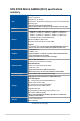
ROG STRIX Z490-G GAMING (WI-FI) specifications summary Intel® Socket LGA1200 for 10th Gen Intel® Core™, Pentium® Gold and Celeron® processors* Supports Intel® 14 nm CPU CPU Supports Intel ® Turbo Boost Technology 2.0 and Intel® Turbo Boost Max Technology 3.0** * Refer to www.asus.com for CPU support list. ** Intel® Turbo Boost Max Technology 3.0 support depends on the CPU types. Chipset Intel® Z490 Chipset 4 x DIMM, Max. 128GB, DDR4 4600(O.C) / 4500(O.C) / 4400(O.C) / 4266(O.C.) / 4133(O.C.) / 4000(O.C.
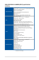
ROG STRIX Z490-G GAMING (WI-FI) specifications summary Intel® Wi-Fi 6 AX201 2x2 Wi-Fi 6 (802.11 a/b/g/n/ac/ax) support 1024QAM/OFDMA/MU-MIMO Supports up to 2.4Gbps max data rate Wireless & Bluetooth Supports 2.4/5GHz Dual-Band Supports channel bandwidth: HT20/HT40/HT80/HT160 Supports CNVI interface Bluetooth v5.1* * BT 5.1 function will be ready in Windows 10 build 19041 or later. Rear USB (Total 8 ports) 2 x USB 3.2 Gen 2 ports (1 x Type-A + 1 x USB Type-C®) 4 x USB 3.
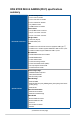
ROG STRIX Z490-G GAMING (WI-FI) specifications summary Fan and cooling related 1 x 4-Pin CPU Fan header 1 x 4-Pin CPU OPT Fan header 2 x 4-Pin Chassis Fan headers 1 x W_PUMP+ header 1 x VRM heatsink Fan header Power related 1 x 24-pin Main Power connector 1 x 8-pin +12V Power connector 1 x 4-pin +12V Power connector Storage related 2 x M.2 slots (Key M) Internal I/O connectors 6 x SATA 6Gb/s ports USB 1 x USB 3.2 Gen 2 Front Panel connector (supports USB Type-C®) 1 x USB 3.
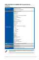
ROG STRIX Z490-G GAMING (WI-FI) specifications summary AURA Sync Special Features - Standard RGB headers - Addressable Gen 2 RGB headers ROG Exclusive Software - RAMCache III - ROG CPU-Z - GameFirst VI - Sonic Studio III + Sonic Studio Virtual Mixer - Sonic Radar III - DTS® Sound Unbound - Overwolf - Anti-virus software ASUS Exclusive Software Armoury Crate - Aura Creator - Aura Sync AI Suite 3 Software Features - 5-Way Optimization with AI Overclocking TPU EPU Digi+ VRM Xpert 4 Turbo app - EZ update AI
Connectors with shared bandwidth B B A A Configuration A 1 (Default) 2 PCIEX16_2 x2 x4 SATA6G_56 V - 1 (Default) 2 PCIe mode SATA mode V - Configuration B x M.2_2 SATA6G_2 • When PCIe 3.0 x16_2 runs at x4 mode, SATA6G_56 will be disabled. • M.2_2 shares bandwidth with SATA6G_2. When M.2_2 runs SATA mode, SATA6G_2 will be disabled. • Please adjust BIOS setting for changing onboard device configuration.
Package contents Check your motherboard package for the following items. Motherboard 1 x ROG STRIX Z490-G GAMING (WI-FI) motherboard 1 x Addressable RGB extension cable Cables 1 x RGB extension cable 4 x SATA 6Gb/s cables 1 x Cable ties pack 1 x M.2 Rubber package Miscellaneous 1 x M.
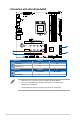
Installation tools and components Phillips (cross) screwdriver PC chassis Power supply unit Intel® LGA 1200 CPU Intel® LGA 1200 compatible CPU Fan DDR4 DIMM SATA hard disk drive SATA optical disc drive (optional) Graphics card (optional) M.2 SSD module (optional) 1 Bag of screws The tools and components in the table above are not included in the motherboard package.
Product Introduction Product Introduction 1.1 Before you proceed 1 Chapter 1 Chapter 1: Take note of the following precautions before you install motherboard components or change any motherboard settings. • Unplug the power cord from the wall socket before touching any component. • Before handling components, use a grounded wrist strap or touch a safely grounded object or a metal object, such as the power supply case, to avoid damaging them due to static electricity.
1.
ROG STRIX Z490-G GAMING (WI-FI) Page 1-4 1-5 1-7 1-8 1-10 1-10 1-11 1-12 1-12 1-13 1-13 1-14 1-15 1-16 1-17 1-17 1-18 1-19 1-19 1-20 Chapter 1 Layout contents 1. CPU socket 2. DIMM slots 3. Expansion slots 4. Fan and Pump headers 5. VRM Heatsink Fan header 6. Power connectors 7. M.2 slot 8. SATA 6GB/s ports 9. USB 3.2 Gen 2 Front Panel connector 10. USB 3.2 Gen 1 header 11. USB 2.0 header 12. AURA Addressable Gen2 header 13. AURA RGB header 14. Clear CMOS header 15. CPU Over Voltage jumper 16.
1. CPU socket The motherboard comes with a LGA1200 socket designed for 10th Gen Intel® Core™, Pentium® Gold and Celeron® processors. Chapter 1 1-4 • Ensure that you install the correct CPU designed for LGA1200 socket only. DO NOT install a CPU designed for other sockets on the LGA1200 socket. • The CPU fits in only one correct orientation. DO NOT force the CPU into the socket to prevent bending the connectors on the socket and damaging the CPU.
2. DIMM slots The motherboard comes with Dual Inline Memory Modules (DIMM) slots designed for DDR4 (Double Data Rate 4) memory modules. Chapter 1 A DDR4 memory module is notched differently from a DDR, DDR2, or DDR3 module. DO NOT install a DDR, DDR2, or DDR3 memory module to the DDR4 slot.
Memory configurations You may install 4 GB, 8 GB, 16 GB, and 32 GB unbuffered and non‑ECC DDR4 DIMMs into the DIMM sockets. Chapter 1 You may install varying memory sizes in Channel A and Channel B. The system maps the total size of the lower-sized channel for the dual-channel configuration. Any excess memory from the higher-sized channel is then mapped for single-channel operation.
3. Expansion slots Chapter 1 Unplug the power cord before adding or removing expansion cards. Failure to do so may cause you physical injury and damage motherboard components. Please refer to the following tables for the recommended VGA configuration and Hyper M.2 configuration.
Recommended VGA configuration Chapter 1 Slot Description 1. PCIe 3.0 x16_1 3. PCIe 3.0 x16_2 Single VGA x16 N/A Dual VGA X16 x4 • We recommend that you provide sufficient power when running CrossFireX™ mode. • Ensure to connect the 8-pin and 4-pin power plugs when running CrossFireX™ mode. • Connect a chassis fan to the chassis fan connectors when using multiple graphics cards for better thermal environment. Hyper M.2 X16 series card configuration Slot Description 1. 1-8 PCIe 3.
4. Fan and Pump headers Chapter 1 The Fan and Pump headers allow you to connect fans or pumps to cool the system. • DO NOT forget to connect the fan cables to the fan headers. Insufficient air flow inside the system may damage the motherboard components. These are not jumpers! Do not place jumper caps on the fan headers! • Ensure the cable is fully inserted into the header. For water cooling kits, connect the pump connector to the W_PUMP+ header.
5. VRM Heatsink fan header The VRM Heatsink fan header is for connecting the VRM Heatsink fan on the integrated heatsink.
6. Power connectors Chapter 1 These Power connectors allow you to connect your motherboard to a power supply. The power supply plugs are designed to fit in only one orientation, find the proper orientation and push down firmly until the power supply plugs are fully inserted. Ensure to connect the 8-pin power plug. • For a fully configured system, we recommend that you use a power supply unit (PSU) that complies with ATX 12V Specification 2.0 (or later version) and provides a minimum power of 350 W.
7. M.2 slot The M.2 slot allows you to install M.2 SSD modules. Chapter 1 • M.2_1 slot supports PCIe 3.0 x4 mode Key M design and type 2242 / 2260/ 2280 / 22110 storage devices. • M.2_2 slot supports PCIe 3.0 x4 and SATA mode Key M design and type 2242 / 2260 / 2280 storage devices. • M.2 slots supports IRST (Intel® Rapid Storage Technology). The M.2 SSD module is purchased separately.
8. SATA 6Gb/s ports Chapter 1 The SATA 6Gb/s ports allows you to connect SATA devices such as optical disc drives and hard disk drives via a SATA cable. If you installed SATA storage devices, you can create a RAID 0, 1, 5, and 10 configuration with the Intel® Rapid Storage Technology through the onboard Intel® Z490 chipset. 9. • The slots are set to [AHCI] by default.
10. USB 3.2 Gen 1 header The USB 3.2 Gen 1 header allows you to connect a USB 3.2 Gen 1 module for additional USB 3.2 Gen 1 ports. The USB 3.2 Gen 1 header provides data transfer speeds of up to 5 Gb/s. Chapter 1 The USB 3.2 Gen 1 module is purchased separately. 11. USB 2.0 header The USB 2.0 header allows you to connect a USB module for additional USB 2.0 ports. The USB 2.0 header provides data transfer speeds of up to 480 Mb/s connection speed. DO NOT connect a 1394 cable to the USB connectors.
12. AURA Addressable Gen2 header Chapter 1 The Addressable Gen2 header allows you to connect individually addressable RGB WS2812B LED strips or WS2812B based LED strips. The Addressable Gen2 header supports WS2812B addressable RGB LED strips (5V/ Data/Ground), with a maximum power rating of 3A (5V), and the addressable headers on this board can handle a combined maximum of 500 LEDs.
13. AURA RGB header The AURA RGB header allows you to connect RGB LED strips. Chapter 1 The AURA RGB header supports 5050 RGB multi-color LED strips (12V/G/R/B), with a maximum power rating of 3A (12V). Before you install or remove any component, ensure that the power supply is switched off or the power cord is detached from the power supply. Failure to do so may cause severe damage to the motherboard, peripherals, or components. 1-16 • Actual lighting and color will vary with LED strip.
14. Clear CMOS header Chapter 1 The Clear CMOS header allows you to clear the Real Time Clock (RTC) RAM in the CMOS, which contains the date, time, system passwords, and system setup parameters. To erase the RTC RAM: 1. Turn OFF the computer and unplug the power cord. 2. Short-circuit pin 1-2 with a metal object or jumper cap for about 5-10 seconds. 3. Plug the power cord and turn ON the computer. 4. Hold down the key during the boot process and enter BIOS setup to re-enter data.
15. CPU Over Voltage jumper Chapter 1 The CPU Over Voltage jumper allows you to set a higher CPU voltage for a flexible overclocking system (depending on the type of the installed CPU). Set to pins 2-3 to increase the CPU voltage setting, or set to pins 1-2 to use the default CPU voltage setting. 16. Front Panel Audio header The front panel audio header is for a chassis-mounted front panel audio I/O module that supports HD Audio. Connect one end of the front panel audio I/O module cable to this header.
17. System Panel header Chapter 1 The System Panel header supports several chassis-mounted functions. • System Power LED header (PLED) The 2-pin header allows you to connect the System Power LED. The System Power LED lights up when the system is connected to a power source, or when you turn on the system power, and blinks when the system is in sleep mode. • Storage Device Activity LED header (HDD_LED) The 2-pin header allows you to connect the Storage Device Activity LED.
18. Thermal Sensor header Chapter 1 The Thermal Sensor header allows you to connect a sensor to monitor the temperature of the devices and the critical components inside the motherboard. Connect the thermal sensor and place it on the device or the motherboard’s component to detect its temperature. The thermal sensor is purchased separately. 19. Q-LEDs The Q-LEDs check key components (CPU, DRAM, VGA, and booting devices) during the motherboard booting process.
20. 8-pin Power Plug LED Chapter 1 The 8-pin Power Plug LED lights up to indicate that the 8-pin power plug is not connected.
Chapter 1 1-22 Chapter 1: Product Introduction
Chapter 2: Basic Installation Basic Installation 2.1 Building your PC system 2 The diagrams in this section are for reference only. The motherboard layout may vary with models, but the installation steps are the same for all models. CPU installation • Ensure that you install the correct CPU designed for LGA1200 socket only. DO NOT install a CPU designed for LGA1155, LGA1156, and LGA1151 sockets on the LGA1200 socket.
Chapter 2 2-2 Chapter 2: Basic Installation
2.1.2 Cooling system installation Apply Thermal Interface Material to the CPU cooling system and CPU before you install the cooling system, if necessary.
To install an AIO cooler If you wish to install an AIO cooler, we recommend installing the AIO cooler after installing the motherboard into the chassis.
DIMM installation Chapter 2 2.1.
2.1.4 M.2 installation 1 2 1 Chapter 2 • The M.2 rubber pad is optional for when installing a single sided M.2 storage device. Ensure to install the bundled M.2 rubber pad before installing your single sided M.2 storage device. • DO NOT install the bundled M.2 rubber pads when installing a double-sided M.2 storage device. The rubber pad installed by default is compatible with double sided M.2 storage devices.
8 7 8 6 Chapter 2 The M.2 is purchased separately.
2.1.5 Motherboard installation Chapter 2 1. Place the motherboard into the chassis, ensuring that its rear I/O ports are aligned to the chassis’ rear I/O panel. 2. Place eight (8) screws into the holes indicated by circles to secure the motherboard to the chassis. DO NOT over tighten the screws! Doing so can damage the motherboard.
ATX power connection Chapter 2 2.1.6 OR AND • DO NOT connect the 4-pin power plug only, the motherboard may overheat under heavy usage. • Ensure to connect the 8-pin power plug, or connect both the 8-pin and 4-pin power plugs.
2.1.
2.1.8 Front I/O connector To install front panel connector To install USB 3.2 Gen 2 connector USB 3.2 Gen 2 To install USB 3.2 Gen 1 connector Chapter 2 This connector will only fit in one orientation. Push the connector until it clicks into place. To install USB 2.0 connector USB 3.2 Gen 1 USB 2.
2.1.
2.1.10 Wi-Fi antenna installation Installing the ASUS 2x2 dual band W-Fi antenna Chapter 2 Connect the bundled ASUS 2x2 dual band Wi-Fi antenna connector to the Wi-Fi ports at the back of the chassis. • Ensure that the ASUS 2x2 dual band Wi-Fi antenna is securely installed to the Wi-Fi ports. • Ensure that the antenna is at least 20 cm away from all persons. The illustration above is for reference only.
2.2 BIOS update utility BIOS FlashBack™ BIOS FlashBack™ allows you to easily update the BIOS without entering the existing BIOS or operating system. Simply insert a USB storage device to the USB port (the USB port hole is marked on the I/O shield) then press the BIOS FlashBack™ button for three seconds to automatically update the BIOS. To use BIOS FlashBack™: 1. Insert a USB storage device to the BIOS FlashBack™ port. We recommend you to use a USB 2.
Motherboard rear and audio connections 2.3.1 Rear I/O connection Chapter 2 2.3 Rear panel connectors 1. 2. 3. 4. 5. 6. 7. 8. DisplayPort USB 3.2 Gen 1 Type-A ports 1, 2, 9 and 10 Intel® I225-V Ethernet port HDMI™ port USB 2.0 ports 11 and 12 BIOS FlashBack™ button USB 3.2 Gen 2 Type-A port 3 USB 3.2 Gen 2 Type-C® port C4 9. Wi-Fi 6 (802.11 a/b/g/n/ac/ax), Bluetooth V5.1 10. Optical S/PDIF out port 11. Gold-plated audio jacks* * Refer to the table on the next page for audio port definitions.
* Audio 2, 4, 5.1 or 7.1-channel configuration 4-channel 5.1-channel 7.1-channel Light Blue Lime Pink Orange Headset 2-channel Line In Line Out Mic In – Line In Front Speaker Out Mic In – Black – Rear Speaker Out Line In Front Speaker Out Mic In Center/Sub woofer Rear Speaker Out Side Speaker Out Front Speaker Out Mic In Center/Sub woofer Rear Speaker Out Port 2.3.
Connect to 2-channel Speakers Chapter 2 Connect to 4-channel Speakers Connect to 5.
Connect to 7.
2.4 Starting up for the first time 1. After making all the connections, replace the system case cover. 2. Ensure that all switches are off. 3. Connect the power cord to the power connector at the back of the system chassis. 4. Connect the power cord to a power outlet that is equipped with a surge protector. 5. Turn on the devices in the following order: Monitor b. External storage devices (starting with the last device on the chain) c.
Chapter 2 2-20 Chapter 2: Basic Installation
Chapter 3: BIOS and RAID Support BIOS and RAID Support 3 For more details on BIOS and RAID configurations, please refer to www.asus.com/ support. 3.1 Knowing BIOS The new ASUS UEFI BIOS is a Unified Extensible Interface that complies with UEFI architecture, offering a user-friendly interface that goes beyond the traditional keyboardonly BIOS controls to enable a more flexible and convenient mouse input. You can easily navigate the new UEFI BIOS with the same smoothness as your operating system.
3.2 BIOS setup program Use the BIOS Setup to update the BIOS or configure its parameters. The BIOS screen include navigation keys and brief onscreen help to guide you in using the BIOS Setup program. Entering BIOS at startup To enter BIOS Setup at startup, press or during the Power-On Self Test (POST). If you do not press or , POST continues with its routines. Entering BIOS Setup after POST To enter BIOS Setup after POST: • Press ++ simultaneously.
3.4 ASUS EZ Flash 3 The ASUS EZ Flash 3 feature allows you to update the BIOS without using an OS‑based utility. Ensure to load the BIOS default settings to ensure system compatibility and stability. Select the Load Optimized Defaults item under the Exit menu or press hotkey . To update the BIOS: • This function can support devices such as a USB flash disk with FAT 32/16 format and single partition only.
3.5 ASUS CrashFree BIOS 3 The ASUS CrashFree BIOS 3 utility is an auto recovery tool that allows you to restore the BIOS file when it fails or gets corrupted during the updating process. You can restore a corrupted BIOS file using the motherboard support DVD or a USB flash drive that contains the BIOS file. The BIOS file in the motherboard support DVD may be older than the BIOS file published on the ASUS official website. If you want to use the newer BIOS file, download the file at https://www.asus.
3.6 RAID configurations The motherboard comes with the Intel® Rapid Storage Technology that supports RAID 0, RAID 1, RAID 5 and RAID 10 configuration. For more information on configuring your RAID sets, please refer to the RAID Configuration Guide which you can find at https://www.asus.com/support, or by scanning the QR code. RAID definitions RAID 0 (Data striping) optimizes two identical hard disk drives to read and write data in parallel, interleaved stacks.
Chapter 3 3-6 Chapter 3: BIOS Setup
Appendix Appendix Notices FCC Compliance Information Responsible Party: Asus Computer International Address: 48720 Kato Rd., Fremont, CA 94538, USA Phone / Fax No: (510)739-3777 / (510)608-4555 Identification of the assembled product: INTEL® WI-FI 6 AX201 Identification of the modular components used in the assembly: Model Name: INTEL® WI-FI 6 AX201 FCC ID: PD9AX201NG This device complies with part 15 of the FCC Rules.
Compliance Statement of Innovation, Science and Economic Development Canada (ISED) This device complies with Innovation, Science and Economic Development Canada licence exempt RSS standard(s). Operation is subject to the following two conditions: (1) this device may not cause interference, and (2) this device must accept any interference, including interference that may cause undesired operation of the device.
Google™ License Terms Copyright© 2020 Google Inc. All Rights Reserved. Licensed under the Apache License, Version 2.0 (the “License”); you may not use this file except in compliance with the License. You may obtain a copy of the License at: http://www.apache.org/licenses/LICENSE-2.0 Unless required by applicable law or agreed to in writing, software distributed under the License is distributed on an “AS IS” BASIS, WITHOUT WARRANTIES OR CONDITIONS OF ANY KIND, either express or implied.
Declaration of compliance for product environmental regulation ASUS follows the green design concept to design and manufacture our products, and makes sure that each stage of the product life cycle of ASUS product is in line with global environmental regulations. In addition, ASUS disclose the relevant information based on regulation requirements. Please refer to http://csr.asus.com/Compliance.
DO NOT throw the motherboard in municipal waste. This product has been designed to enable proper reuse of parts and recycling. This symbol of the crossed out wheeled bin indicates that the product (electrical and electronic equipment) should not be placed in municipal waste. Check local regulations for disposal of electronic products. DO NOT throw the mercury-containing button cell battery in municipal waste.
Appendix Simplified EU Declaration of Conformity ASUSTek Computer Inc. hereby declares that this device is in compliance with the essential requirements and other relevant provisions of Directive 2014/53/EU. Full text of EU declaration of conformity is available at https://www.asus.com/support/ The WiFi operating in the band 5150-5350MHz shall be restricted to indoor use for countries listed in the table below: Déclaration simplifiée de conformité de l’UE ASUSTek Computer Inc.
ROG STRIX Z490-G GAMING (WI-FI) ประกาศเกี่ยวกับความสอดคล้องของสหภาพยุโรปแบบย่อ ASUSTek Computer Inc. ขอประกาศในที่นี้ว่าอุปกรณ์นี้มีความสอดคล้องกับความ ต้องการที่จำ�เป็นและเงื่อนไขที่เกี่ยวข้องอื่น ๆ ของบทบัญญัติข้อกำ�หนด 2014/53/EU เนื้อหาที่สมบูรณ์ของประกาศความสอดคล้องกับ EU มีอยู่ที่ https://www.asus.com/support/ การทำ�งานของ WiFi ที่ 5150-5350MHz ถูกจำ�กัดให้ใช้ในอาคารสำ�หรับประเทศที่แสดงในตาราง Basitleştirilmiş AB Uyumluluk Bildirimi ASUSTek Computer Inc.
ASUS contact information ASUSTeK COMPUTER INC. Address Telephone Fax Web site Technical Support Telephone Online support 1F., No. 15, Lide Rd., Beitou Dist., Taipei City 112, Taiwan +886-2-2894-3447 +886-2-2890-7798 https://www.asus.com +86-21-38429911 https://qr.asus.com/techserv ASUS COMPUTER INTERNATIONAL (America) Address 48720 Kato Rd., Fremont, CA 94538, USA Telephone +1-510-739-3777 Fax +1-510-608-4555 Web site https://www.asus.