
User Manual
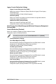
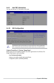
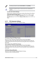
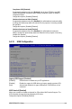
Table Of Contents
- Safety information
- Chapter 1: Product Introduction
- Chapter 2: Hardware Information
- 2.1 Chassis cover
- 2.2 Central Processing Unit (CPU)
- 2.3 System memory
- 2.4 Storage devices
- 2.5 Expansion slot
- 2.5.1 Installing an expansion card to the PCIe x16 slot on the butterfly riser card bracket
- 2.5.2 Installing an expansion card to the PCIe x8 slot on the butterfly riser card bracket
- 2.5.3 (optional) Installing an Intel® X710 10G LAN card to the onboard PCIe slot
- 2.5.4 Installing an M.2 module
- 2.5.5 Installing the Baseboard Management Card
- 2.5.6 (optional) Installing the PFR module
- 2.5.7 Configuring an expansion card
- 2.6 Cable connections
- 2.7 Removable/optional components
- Chapter 3: Installation Options
- Chapter 4: Motherboard Information
- Chapter 5: BIOS Setup
- 5.1 Managing and updating your BIOS
- 5.2 BIOS setup program
- 5.3 Main menu
- 5.4 Advanced menu
- 5.4.1 CPU Configuration
- 5.4.2 Power & Performance
- 5.4.3 Server ME Configuration
- 5.4.4 System Event Log
- 5.4.5 Trusted Computing
- 5.4.6 Redfish Host Interface Settings
- 5.4.7 Onboard LAN Configuration
- 5.4.8 Serial Port Console Redirection
- 5.4.9 Intel TXT Information
- 5.4.10 SIO Configuration
- 5.4.11 PCI Subsystem Settings
- 5.4.12 USB Configuration
- 5.4.13 Network Stack Configuration
- 5.4.14 CSM (Compatibility Support Module)
- 5.4.15 NVMe Configuration
- 5.4.16 APM Configuration
- 5.4.17 Third-party UEFI driver configurations
- 5.5 Chipset menu
- 5.6 Security menu
- 5.7 Boot menu
- 5.8 Monitor menu
- 5.9 Tool menu
- 5.10 Event Logs menu
- 5.11 Server Mgmt menu
- 5.12 Exit menu
- Chapter 6: RAID Configuration
- Chapter 7: Driver Installation
- Appendix

5-25
ASUS RS300-E11 Series
Maximum Payload [Auto]
Allows you to set Maximum Payload of PCI Express Device or allow System BIOS to
select the value.
Configuration options: [Auto] [128 Bytes] [256 Bytes] [512 Bytes] [1024 Bytes] [2048
Bytes] [4096 Bytes]
Maximum Read Request [Auto]
Allows you to set Maximum Read Request Size of PCI Express Device or allow
System BIOS to select the value.
Configuration options: [Auto] [128 Bytes] [256 Bytes] [512 Bytes] [1024 Bytes] [2048
Bytes] [4096 Bytes]
PCI Express Link Register Settings
ASPM Support [Disabled]
Allows you to set the ASPM level.
[Disabled]
Disables ASPM.
[Auto] BIOS auto configure.
[Force L0s] Force all links to L0 State.
Enabling ASPM may cause some PCI-E devices to fail.
Extended Synch [Disabled]
If this item is enabled, it will allow generation of Extended Synchronization patterns.
Configuration options: [Disabled] [Enabled]
Link Training Retry [5]
Allows you to define the number of Retry Attempts software will take to retrain the link
if previous training attempt was unsuccessful.
Configuration options: [Disabled] [2] [3] [5]
Link Training Timeout (uS) [1000]
Allows you to define the number of Microseconds software will wait before polling ‘link
Training’ bit in Link Status register.
Configuration options: [10] - [10000]
Unpopulated Links [Keep Link ON]
If this option is set to
[Disable Link], in order to save power, software will disable
unpopulated PCI Express Links.
Configuration options: [Keep Link ON] [Disabled Link]
PCI Express GEN 2 Settings
The items in this submenu allow you change PCI Express GEN Devices Settings.
PCI Express GEN2 Device Register Settings
Completion Timeout [Default]
In device Functions that support Completion Timeout programmability, allows system
software to modify the Completion Timeout value.
[Default]
50us to 50ms.
[Shorter] Software will use shorter timeout ranges supported by hardware.
[Longer] Software will use longer timeout ranges.
[Disabled] Disable completion timeout.