
User Manual
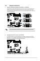
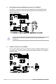
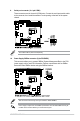
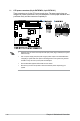
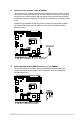
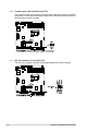
Table Of Contents
- Safety information
- Chapter 1: Product Introduction
- Chapter 2: Hardware Information
- 2.1 Chassis cover
- 2.2 Central Processing Unit (CPU)
- 2.3 System memory
- 2.4 Storage devices
- 2.5 Expansion slot
- 2.5.1 Installing an expansion card to the PCIe x16 slot on the butterfly riser card bracket
- 2.5.2 Installing an expansion card to the PCIe x8 slot on the butterfly riser card bracket
- 2.5.3 (optional) Installing an Intel® X710 10G LAN card to the onboard PCIe slot
- 2.5.4 Installing an M.2 module
- 2.5.5 Installing the Baseboard Management Card
- 2.5.6 (optional) Installing the PFR module
- 2.5.7 Configuring an expansion card
- 2.6 Cable connections
- 2.7 Removable/optional components
- Chapter 3: Installation Options
- Chapter 4: Motherboard Information
- Chapter 5: BIOS Setup
- 5.1 Managing and updating your BIOS
- 5.2 BIOS setup program
- 5.3 Main menu
- 5.4 Advanced menu
- 5.4.1 CPU Configuration
- 5.4.2 Power & Performance
- 5.4.3 Server ME Configuration
- 5.4.4 System Event Log
- 5.4.5 Trusted Computing
- 5.4.6 Redfish Host Interface Settings
- 5.4.7 Onboard LAN Configuration
- 5.4.8 Serial Port Console Redirection
- 5.4.9 Intel TXT Information
- 5.4.10 SIO Configuration
- 5.4.11 PCI Subsystem Settings
- 5.4.12 USB Configuration
- 5.4.13 Network Stack Configuration
- 5.4.14 CSM (Compatibility Support Module)
- 5.4.15 NVMe Configuration
- 5.4.16 APM Configuration
- 5.4.17 Third-party UEFI driver configurations
- 5.5 Chipset menu
- 5.6 Security menu
- 5.7 Boot menu
- 5.8 Monitor menu
- 5.9 Tool menu
- 5.10 Event Logs menu
- 5.11 Server Mgmt menu
- 5.12 Exit menu
- Chapter 6: RAID Configuration
- Chapter 7: Driver Installation
- Appendix

ASUS RS300-E11 Series
4-13
4.4 Internal connectors
The actual data transfer rate depends on the speed of Serial ATA hard disks installed.
1. Serial ATA 6.0 Gbp/s connectors (7-pin SATA6G_1-4; SATA5-6)
Supported by the Intel
®
C252 chipset, these connectors are for the Serial ATA signal
cables for Serial ATA hard disk drives that allows up to 6Gb/s of data transfer rate.
If you installed Serial ATA hard disk drives, you can create a RAID 0, RAID 1, RAID 10,
or RAID 5 configuration.
2. Hard disk activity LED connector (4-pin HDLED1)
This LED connector is for the storage add-on card cable connected to the SATA or
SAS add-on card. The read or write activities of any device connected to the SATA or
SAS add-on card causes the front panel LED to light up.