
User Manual
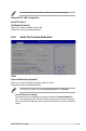
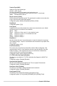
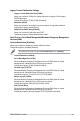
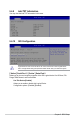
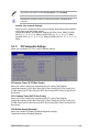
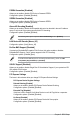
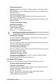
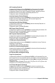
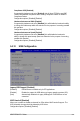

Table Of Contents
- Safety information
- Chapter 1: Product Introduction
- Chapter 2: Hardware Information
- 2.1 Chassis cover
- 2.2 Central Processing Unit (CPU)
- 2.3 System memory
- 2.4 Storage devices
- 2.5 Expansion slot
- 2.5.1 Installing an expansion card to the PCIe x16 slot on the butterfly riser card bracket
- 2.5.2 Installing an expansion card to the PCIe x8 slot on the butterfly riser card bracket
- 2.5.3 (optional) Installing an Intel® X710 10G LAN card to the onboard PCIe slot
- 2.5.4 Installing an M.2 module
- 2.5.5 Installing the Baseboard Management Card
- 2.5.6 (optional) Installing the PFR module
- 2.5.7 Configuring an expansion card
- 2.6 Cable connections
- 2.7 Backplane cabling
- 2.8 Removable/optional components
- Chapter 3: Installation Options
- Chapter 4: Motherboard Information
- Chapter 5: BIOS Setup
- 5.1 Managing and updating your BIOS
- 5.2 BIOS setup program
- 5.3 Main menu
- 5.4 Advanced menu
- 5.4.1 CPU Configuration
- 5.4.2 Power & Performance
- 5.4.3 Server ME Configuration
- 5.4.4 System Event Log
- 5.4.5 Trusted Computing
- 5.4.6 Redfish Host Interface Settings
- 5.4.7 Onboard LAN Configuration
- 5.4.8 Serial Port Console Redirection
- 5.4.9 Intel TXT Information
- 5.4.10 SIO Configuration
- 5.4.11 PCI Subsystem Settings
- 5.4.12 USB Configuration
- 5.4.13 Network Stack Configuration
- 5.4.14 CSM (Compatibility Support Module)
- 5.4.15 NVMe Configuration
- 5.4.16 APM Configuration
- 5.4.17 Third-party UEFI driver configurations
- 5.5 Chipset menu
- 5.6 Security menu
- 5.7 Boot menu
- 5.8 Monitor menu
- 5.9 Tool menu
- 5.10 Event Logs menu
- 5.11 Server Mgmt menu
- 5.12 Exit menu
- Chapter 6: RAID Configuration
- Chapter 7: Driver Installation
- Appendix

5-20
Chapter 5: BIOS Setup
Terminal Type [ANSI]
Allows you to set the terminal type.
[VT100] ASCII char set.
[VT100+] Extends VT100 to support color, function keys, etc.
[VT-UTF8] Uses UTF8 encoding to map Unicode chars onto 1 or more bytes.
[ANSI] Extended ASCII char set.
Bits per second [115200]
Selects serial port transmission speed. The speed must be matched on the other side.
Long or noisy lines may require lower speeds.
Configuration options: [9600] [19200] [38400] [57600] [115200]
Data Bits [8]
Configuration options: [7] [8]
Parity [None]
A parity bit can be sent with the data bits to detect some transmission errors. [Mark]
and [Space] parity do not allow for error detection.
[None]
None
[Even] parity bit is 0 if the num of 1’s in the data bits is even
[Odd] parity bit is 0 if num of 1’s in the data bits is odd
[Mark] parity bit is always 1
[Space] parity bit is always 0
Stop Bits [1]
Stop bits indicate the end of a serial data packet. (A start bit indicates the beginning.)
The standard setting is 1 stop bit. Communication with slow devices may require more
than 1 stop bit.
Configuration options: [1] [2]
Flow Control [None]
Flow control can prevent data loss from buffer overflow. When sending data, if the
receiving buffers are full, a “stop” signal can be sent to stop the data flow. Once the
buffers are empty, a “start” signal can be sent to re-start the flow. Hardware flow
control uses two wires to send start/stop signals.
Configuration options: [None] [Hardware RTS/CTS]
VT -UTF8 Combo Key Support [Enabled]
This allows you to enable the VT -UTF8 Combination Key Support for ANSI/VT100
terminals.
Configuration options: [Disabled] [Enabled]
Recorder Mode [Disabled]
With this mode enabled only text will be sent. This is to capture Terminal data.
Configuration options: [Disabled] [Enabled]
Resolution 100x31 [Enabled]
This allows you to enable or disable extended terminal resolution.
Configuration options: [Disabled] [Enabled]
Putty Keypad [VT100]
This allows you to select the FunctionKey and Keypad on Putty.
Configuration options: [VT100] [LINUX] [XTERMR6] [SCO] [ESCN] [VT400]