
User Manual
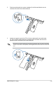
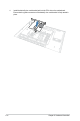
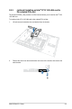
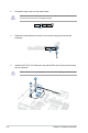
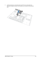
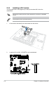
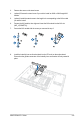
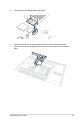
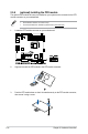
Table Of Contents
- Safety information
- Chapter 1: Product Introduction
- Chapter 2: Hardware Information
- 2.1 Chassis cover
- 2.2 Central Processing Unit (CPU)
- 2.3 System memory
- 2.4 Storage devices
- 2.5 Expansion slot
- 2.5.1 Installing an expansion card to the PCIe x16 slot on the butterfly riser card bracket
- 2.5.2 Installing an expansion card to the PCIe x8 slot on the butterfly riser card bracket
- 2.5.3 (optional) Installing an Intel® X710 10G LAN card to the onboard PCIe slot
- 2.5.4 Installing an M.2 module
- 2.5.5 Installing the Baseboard Management Card
- 2.5.6 (optional) Installing the PFR module
- 2.5.7 Configuring an expansion card
- 2.6 Cable connections
- 2.7 Backplane cabling
- 2.8 Removable/optional components
- Chapter 3: Installation Options
- Chapter 4: Motherboard Information
- Chapter 5: BIOS Setup
- 5.1 Managing and updating your BIOS
- 5.2 BIOS setup program
- 5.3 Main menu
- 5.4 Advanced menu
- 5.4.1 CPU Configuration
- 5.4.2 Power & Performance
- 5.4.3 Server ME Configuration
- 5.4.4 System Event Log
- 5.4.5 Trusted Computing
- 5.4.6 Redfish Host Interface Settings
- 5.4.7 Onboard LAN Configuration
- 5.4.8 Serial Port Console Redirection
- 5.4.9 Intel TXT Information
- 5.4.10 SIO Configuration
- 5.4.11 PCI Subsystem Settings
- 5.4.12 USB Configuration
- 5.4.13 Network Stack Configuration
- 5.4.14 CSM (Compatibility Support Module)
- 5.4.15 NVMe Configuration
- 5.4.16 APM Configuration
- 5.4.17 Third-party UEFI driver configurations
- 5.5 Chipset menu
- 5.6 Security menu
- 5.7 Boot menu
- 5.8 Monitor menu
- 5.9 Tool menu
- 5.10 Event Logs menu
- 5.11 Server Mgmt menu
- 5.12 Exit menu
- Chapter 6: RAID Configuration
- Chapter 7: Driver Installation
- Appendix

Chapter 2: Hardware Information
2-22
5. Install the Intel
®
X710 10G LAN card to the onboard PCIe slot (A), then secure it using
two (2) screws (B).
Ensure to watch out for the metal bracket of the rear IO when installing the expansion card.
3. Remove the metal cover from the metal bracket.
Take extra care when removing the metal cover. Use tools such as a screw driver to bend
and remove the metal cover to avoid physical injury.
4. Replace the metal bracket and secure it to the chassis using the screw removed
previously.