
User Manual
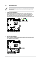
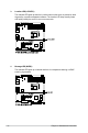
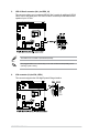
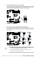
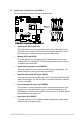
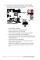
Table Of Contents
- Safety information
- Chapter 1: Product Introduction
- Chapter 2: Hardware Information
- 2.1 Chassis cover
- 2.2 Central Processing Unit (CPU)
- 2.3 System memory
- 2.4 Storage devices
- 2.5 Expansion slot
- 2.5.1 Installing an expansion card to the PCIe x16 slot on the butterfly riser card bracket
- 2.5.2 Installing an expansion card to the PCIe x8 slot on the butterfly riser card bracket
- 2.5.3 (optional) Installing an Intel® X710 10G LAN card to the onboard PCIe slot
- 2.5.4 Installing an M.2 module
- 2.5.5 Installing the Baseboard Management Card
- 2.5.6 (optional) Installing the PFR module
- 2.5.7 Configuring an expansion card
- 2.6 Cable connections
- 2.7 Backplane cabling
- 2.8 Removable/optional components
- Chapter 3: Installation Options
- Chapter 4: Motherboard Information
- Chapter 5: BIOS Setup
- 5.1 Managing and updating your BIOS
- 5.2 BIOS setup program
- 5.3 Main menu
- 5.4 Advanced menu
- 5.4.1 CPU Configuration
- 5.4.2 Power & Performance
- 5.4.3 Server ME Configuration
- 5.4.4 System Event Log
- 5.4.5 Trusted Computing
- 5.4.6 Redfish Host Interface Settings
- 5.4.7 Onboard LAN Configuration
- 5.4.8 Serial Port Console Redirection
- 5.4.9 Intel TXT Information
- 5.4.10 SIO Configuration
- 5.4.11 PCI Subsystem Settings
- 5.4.12 USB Configuration
- 5.4.13 Network Stack Configuration
- 5.4.14 CSM (Compatibility Support Module)
- 5.4.15 NVMe Configuration
- 5.4.16 APM Configuration
- 5.4.17 Third-party UEFI driver configurations
- 5.5 Chipset menu
- 5.6 Security menu
- 5.7 Boot menu
- 5.8 Monitor menu
- 5.9 Tool menu
- 5.10 Event Logs menu
- 5.11 Server Mgmt menu
- 5.12 Exit menu
- Chapter 6: RAID Configuration
- Chapter 7: Driver Installation
- Appendix

ASUS RS300-E11 Series
4-17
9. Serial port connector (10-1 pin COM1)
These connectors are for the serial (COM) ports. Connect the serial port module cable
to the connector, then install the module to a slot opening at the back of the system
chassis.
10. Power Supply SMBus connector (5-pin PSUSMB1)
This connector allows you to connect SMBus (System Management Bus) to the PSU
(power supply unit) to read PSU information. Devices communicate with an SMBus
host and/or other SMBus devices using the SMBus interface.
This connector functions only when you enable the ASUS ASMB10.
Power supply is required to meet PMBus specification and customized BMC FW may be
needed. Please contact ASUS if your need further support.
The COM module is purchased separately.