RS520A-E11-RS12U 2U Rackmount Server User Guide
E21562 Revised Edition V3 January 2023 Copyright © 2023 ASUSTeK COMPUTER INC. All Rights Reserved. No part of this manual, including the products and software described in it, may be reproduced, transmitted, transcribed, stored in a retrieval system, or translated into any language in any form or by any means, except documentation kept by the purchaser for backup purposes, without the express written permission of ASUSTeK COMPUTER INC. (“ASUS”).
Contents Safety information...................................................................................................... vii About this guide.......................................................................................................... ix Chapter 1: Product Introduction 1.1 System package contents.......................................................................... 1-2 1.2 Serial number label.....................................................................................
Contents 2.6 Expansion slot........................................................................................... 2-18 2.6.1 Installing an expansion card to the left PCIe riser card bracket....................................................................................... 2-19 2.6.2 Installing an expansion card to the right PCIe riser card bracket....................................................................................... 2-22 2.6.
Contents Chapter 5: BIOS Setup 5.1 5.2 Managing and updating your BIOS........................................................... 5-2 5.1.1 ASUS CrashFree BIOS 3 utility................................................... 5-2 5.1.2 ASUS EZ Flash Utility.................................................................. 5-3 5.1.3 BUPDATER utility........................................................................ 5-4 BIOS setup program................................................................
Contents 5.9 Tool menu.................................................................................................. 5-32 5.10 Save & Exit menu...................................................................................... 5-33 5.11 AMD CBS menu......................................................................................... 5-34 5.11.1 5.12 5.13 CPU Common Options.............................................................. 5-35 5.11.2 DF Common Options........................
Safety information Electrical Safety • Before installing or removing signal cables, ensure that the power cables for the system unit and all attached devices are unplugged. • To prevent electrical shock hazard, disconnect the power cable from the electrical outlet before relocating the system. • When adding or removing any additional devices to or from the system, ensure that the power cables for the devices are unplugged before the signal cables are connected.
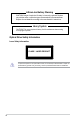
Lithium-Ion Battery Warning CAUTION! Danger of explosion if battery is incorrectly replaced. Replace only with the same or equivalent type recommended by the manufacturer. Dispose of used batteries according to the manufacturer’s instructions. Heavy System CAUTION! This server system is heavy. Ask for assistance when moving or carrying the system.
About this guide Audience This user guide is intended for system integrators, and experienced users with at least basic knowledge of configuring a server. Contents This guide contains the following parts: 1. Chapter 1: Product Introduction This chapter describes the general features of the server, including sections on front panel and rear panel specifications. 2.
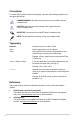
Conventions To ensure that you perform certain tasks properly, take note of the following symbols used throughout this manual. DANGER/WARNING: Information to prevent injury to yourself when trying to complete a task. CAUTION: Information to prevent damage to the components when trying to complete a task. IMPORTANT: Instructions that you MUST follow to complete a task. NOTE: Tips and additional information to help you complete a task. Typography Bold text Indicates a menu or an item to select.
Chapter 1: Product Introduction Product Introduction This chapter describes the general features of the chassis kit. It includes sections on front panel and rear panel specifications.
1.1 System package contents Check your system package for the following items. Model Name RS520A-E11-RS12U Chassis ASUS R2P-C 2U Rackmount Chassis Motherboard ASUS KMPA-U16 Server Board 1+1 800W 80PLUS Platinum or 850W 80PLUS Titanium or 1200W 80PLUS Platinum Redundant Power Supply 1 x 3.5-inch Storage Device Backplane Component 12 x 3.
1.2 Serial number label The product’s serial number contains 12 characters such as xxSxxxxxxxxx and printed on the sticker at the server's front cover. The correct serial number of the product is required if you need to request for support from the ASUS Technical Support team.
1.3 System specifications The ASUS RS520A-E11 Series features the ASUS KMPA-U16 server board. The server supports AMD EPYC™ 7002/7003 Series processors plus other latest technologies through the chipsets onboard.
Model Name RS520A-E11-RS12U Front bays: 12 x 3.5” hot-swap drive bays - 12 x NVMe/SATA/SAS* or - 8 NVMe* + 12 SATA/SAS* Storage Bay Storage Bays * SAS support only from optional HBA/RAID card. ** An optional slot 5 may be expanded, this will limit NVMe support on the front bay to 8 NVMe devices. Rear bays (optional): 2 x 2.5” hot-swap drive bays - 2 x NVMe Motherboard onboard connectors 2 x M.
Model Name RS520A-E11-RS12U Security Options TPM-SPI PFR Windows® Server 2019 64 bit Windows® Server 2016 RedHat® Enterprise Linux SuSE® Linux Enterprise Server OS Support CentOS Ubuntu VMware * Please find the latest OS support from https://www.asus.com/ Software ASUS Control Center Management Out of Band Solution Remote Management On-Board ASMB10-iKVM for KVM-over-IP Regulatory Compliance BSMI, CE, RCM, FCC(Class A) Dimension 840mm x 449mm x 88.1mm (2U) 33.07in x 17.68in x 3.
1.4 Front panel features The barebone server displays a simple yet stylish front panel with easily accessible features. The power and reset buttons, LED indicators are located on the front panel. Refer to section 1.7 LED information for the LED descriptions. USB 3.2 Gen 1 ports Front panel LEDs & buttons 1 2 3 4 RESET handle 12 x 3.5” Storage Bays handle • Bay 1 to bay 12 supports NVMe/SATA/SAS. SAS support requires optional HBA/RAID card.
1.5 Rear panel features The rear panel includes the expansion slots, and system power sockets. The middle part includes the I/O shield with openings for the rear panel connectors on the motherboard. Standard model with no rear storage bay Expansion slots Redundant Power supply and Power cord connector Expansion slot Power button Location button Q-Code LED VGA port USB 3.2 Gen 1 ports Expansion slots Lan port 2 OCP 3.
1.6 Internal features The barebone server includes the basic components as shown. Standard model with no rear storage bay 1. Redundant Power supply 2. ASUS KMPA-U16 Server Board 3. SATA/SAS/NVMe back panel 4. Front USB panel 5. System fans 6. Asset Tag (hidden) 7. 12 x 3.5“ storage device trays 8. PCIe riser cards 9. Front I/O panel The barebone server does not include a floppy disk drive.
Standard model with rear storage bay 1. Redundant Power supply (hidden) 2. 2 x 2.5“ storage device trays 3. ASUS KMPA-U16 Server Board 4. SATA/SAS/NVMe back panel 5. Front USB panel 6. System fans 7. Asset Tag (hidden) 8. 12 x 3.5“ storage device trays 9. PCIe riser cards 10. Front I/O panel The barebone server does not include a floppy disk drive. Connect a USB floppy disk drive to any of the USB ports on the front or rear panel if you need to use a floppy disk.
1.7 LED information 1.7.
1.7.2 Storage device status LED 1 2 3 4 RESET Green LED Red LED Storage Device LED Description Status (RED) Activity (GREEN) 1.7.
1.7.
1.7.
Action PHASE PSP Boot PSP Boot Loader phase (Error Post Codes) POST CODE 0x39 0x3A 0x3B 0x3C 0x3D 0x3E 0x3F 0x40 0x41 0x42 0x43 0x44 0x45 0x46 0x47 0x48 0x49 0x4A 0x4B 0x4C 0x4D 0x4E 0x4F 0x50 0x51 0x52 0x53 0x54 0x55 0x56 0x57 0x58 0x59 0x5A 0x5B 0x5C 0x5E 0x5F 0x60 0x61 0x62 0x63 0x64 0x65 0x66 0x67 TYPE Error Error Error Error Error Error Error Error Error Error Error Error Error Error Error Error Error Error Error Error Error Error Error Error Error Error Error Error Error Error Error Error Error E
Action PHASE PSP Boot PSP Boot Loader phase (Status Post Codes) POST CODE 0xA0 0xA1 0xA2 0xA3 0xA4 0xA5 0xA6 0xA7 0xA8 0xA9 0xAA 0xAB 0xAC 0xAD 0xAE 0xAF 0xB0 0xB1 0xB2 0xB3 0xB4 0xB5 0xB6 0xB7 0xB8 0xB9 0xBA 0xBB 0xBC 0xBD 0xBE 0xBF 0xC0 0xC1 0xC2 0xC3 0xC4 0xC5 0xC6 0xC7 0xC8 0xC9 0xCA 0xCB 0xCC 0xCD 0xCE 0xCF 0xD0 0xD1 0xD2 0xD3 0xD4 0xD5 0xD6 0xD7 0xD8 0xD9 TYPE Progress Progress Progress Progress Progress Progress Progress Progress Progress Progress Progress Progress Progress Progress Progress Pro
Action PHASE PEI(Pre-EFI Initialization) phase Quick VGA DXE(Driver Execution Environment) phase Normal boot BDS(Boot Device Selection) phase Operating system phase POST CODE 0x10 0x11 0x15 0x19 0x32 0x33 0x34 0x35 0x36 0x37 0x3B 0x4F 0x60 0x61 0x62 0x63 0x68 0x69 0x6A 0x70 0x71 0x72 0x78 0x79 0xD0 0x90 0x91 0x92 0x93 0x94 0x95 0x96 0x97 0x98 0x99 0x9A 0x9B 0x9C 0x9D 0xb2 0xb3 0xb4 0xb6 0xb7 0xA0 0xA1 0xA2 0xA3 0x00~0xFF 0xA8 0xA9 0xAB 0xAD 0xAE 0xAA 0xAC ASUS RS520A-E11-RS12U TYPE Progress Progress
AMD EPYC™ 7003 Series processors Action PHASE SEC Start up Security Phase PSP Boot PSP Boot Loader phase (Error Post Codes) POST CODE 0x01 0x02 0x03 0x04 0x05 0x06 0x00 0x01 0x02 0x03 0x04 0x05 0x06 0x07 0x08 0x09 0x0A 0x0B 0x0C 0x0D 0x0E 0x0F 0x10 0x11 0x12 0x13 0x14 0x15 0x16 0x17 0x18 0x19 0x1A 0x1B 0x1C 0x1D 0x1E 0x1F 0x20 0x21 0x22 0x23 0x24 0x25 0x26 0x27 0x28 0x29 0x2A 0x2B 0x2C 0x2D 0x2E 0x2F 0x30 0x31 0x32 0x33 0x34 0x35 0x36 0x37 0x38 0x39 TYPE Progress Progress Progress Progress Progress Pr
Action PSP Boot PHASE PSP Boot Loader phase (Error Post Codes) POST CODE 0x3A 0x3B 0x3C 0x3D 0x3E 0x3F 0x40 0x41 0x42 0x43 TYPE error error error error error error error error error error 0x44 error 0x45 0x46 0x47 0x48 0x49 0x4A 0x4B 0x4C 0x4D 0x4E 0x4F 0x50 0x51 0x52 0x53 0x54 0x55 0x56 0x57 0x58 0x59 0x5A 0x5B 0x5C 0x5E 0x5F 0x60 0x61 0x62 0x63 0x64 0x65 0x66 0x67 error error error error error error error error error error error error error error error error error error error error error error er
Action PSP Boot PHASE PSP Boot Loader phase (Status Post Codes) PEI(Pre-EFI Initialization) phase Quick VGA DXE(Driver Execution Environment) phase POST CODE 0x7B 0x7C TYPE error error 0x7D error 0x7E 0x7F 0x80 error error error 0x81 error 0x82 error 0x83 0x84 error error 0x85 error 0x86 0x87 0x88 0x89 0x8A 0x8B 0x8C 0x8D 0x8E error error error error error error error error error 0x8F error 0x90 0x91 error error 0x92 error 0x93 0x94 0x95 0x96 0x97 0x98 0x99 0x9A 0x9B 0x9C 0x9D 0x
Action Normal boot PHASE BDS(Boot Device Selection) phase Operating system phase POST CODE 0x90 0x91 0x92 0x93 0x94 0x95 0x96 0x97 0x98 0x99 0x9A 0x9B 0x9C 0x9D 0xb2 0xb3 0xb4 0xb6 0xb7 0xA0 0xA1 0xA2 0xA3 0x00~0xFF 0xA8 0xA9 0xAB 0xAD 0xAE 0xAA 0xAC ASUS RS520A-E11-RS12U TYPE Progress Progress Progress Progress Progress Progress Progress Progress Progress Progress Progress Progress Progress Progress Progress Progress Progress Progress Progress Progress Progress Progress Progress Progress Progress Pr
1-22 Chapter 1: Product Introduction
Chapter 2: Hardware Information Hardware Information This chapter lists the hardware setup procedures that you have to perform when installing or removing system components.
2-2 2.1 Chassis cover 2.1.1 Removing the rear cover 1. Remove the two (2) screws on both sides of the rear cover with a Phillips screwdriver. 2. Push the buttons on both sides to release the rear cover from the chassis. 3. Slide the rear cover towards the rear panel to disengage it from the chassis. 4. Lift the rear cover from the chassis.
2.1.2 Removing the mid cover 1. Remove the two (2) screws on both sides of the mid cover with a Phillips screwdriver. 2. Push the buttons on both sides to release the mid cover from the chassis. 3. Slide the mid cover towards the rear panel to disengage it from the chassis. 4. Lift the mid cover from the chassis.
2.2 Air ducts 2.2.1 Removing the air ducts Remove the two (2) screws from the air ducts, then gently lift the air ducts vertically out of the chassis. 2.2.2 Installing the air ducts Align the air duct notch holes to the notches in the system, then install the air ducts into the chassis and secure it with the two (2) screws removed previously.
2.3 Central Processing Unit (CPU) The motherboard comes with a surface mount Socket SP3 designed for the AMD EPYC™ 7002/7003 Series. 2.3.1 • Upon purchase of the motherboard, ensure that the PnP cap is on the socket and the socket contacts are not bent. Contact your retailer immediately if the PnP cap is missing, or if you see any damage to the PnP cap/socket contacts/motherboard components. ASUS will shoulder the cost of repair only if the damage is shipment/ transit-related.
4. Locate the CPU socket on your motherboard.. 5. Loosen each screw one by one in the sequence shown on the socket to open the load plate. 6. Slightly lift open the rail frame.
7. Slide the external cap out of the rail frame. External cap Rail frame PnP cap 8. Slide the carrier frame with CPU into the rail frame, then remove the PnP cap. The carrier frame with CPU fits in only one correct orientation. DO NOT force the carrier frame with CPU into the rail frame. Carrier frame with CPU Rail frame PnP cap 9. Gently push the rail frame just enough to let it sit on top of the CPU socket.
10. Close the load plate just enough to let it sit on top of the CPU, then secure each screw one by one in the sequence shown on the socket to completely secure the load plate. The load plate screws are T20 models. A torque value of 16.1±1.2 kgf-cm (14.0±1.0 lbf-in) is recommended. 11. Twist each of the four screws with a screwdriver just enough to attach the heatsink to the motherboard.
12. Align the left PCIe riser card bracket to the notch holes on the chassis and the PCIE1 slot on the motherboard. Please refer to the illustration below for the locations of the notch holes on the chassis. Ensure that no cables are below or in the way of the PCIe riser card bracket when installing it to the chassis. 13. Push the left PCIe riser card bracket down until it is seated firmly in the chasiss.
2.4 System memory 2.4.1 Overview The motherboard comes with 16 Double Data Rate 4 (DDR4) Dual Inline Memory Modules (DIMM) sockets. The figure illustrates the location of the DDR4 DIMM sockets: 2.4.2 Memory Configurations You may install 16GB, 32GB, or 64GB RDIMM into the DIMM sockets. If you are not sure on which slots to install the DIMMS, you can use the recommended memory configuration in this section for reference.
2.4.3 Installing a DIMM Ensure to unplug the power supply before adding or removing DIMMs or other system components. Failure to do so may cause severe damage to both the motherboard and the components. 1. Unlock a DIMM socket by pressing the retaining clips outward. 2. Align a DIMM on the socket such that the notch on the DIMM matches the DIMM slot key on the socket. DIMM notch DIMM slot key Unlocked retaining clip A DIMM is keyed with a notch so that it fits in only one direction.
2.5 Storage devices The system supports twelve (12) 3.5” hot-swap SATA/SAS/NVMe storage devices. NVMe support may vary between 12 x NVMe for all front bays, or 10 x NVMe on the front bay and 2 x NVMe on the optional rear bay depending on the model. The storage device installed on the storage device tray connects to the motherboard SATA/SAS/NVMe ports via the SATA/SAS/ NVMe backplane. Bay 1 Bay 2 Bay 4 Bay 5 Bay 7 Bay 8 Bay 10 Bay 11 1 2 3 4 RESET Bay 3 2.5.1 1.
2. Firmly hold the tray lever and pull the storage device tray out of the bay. 3. Place the storage device tray on a flat and stable surface. 4. Prepare the 3.5” storage device and the bundled set of screws. 5. Place the 3.5” storage device into the tray then secure it with four screws. 6. Carefully insert the tray and push it all the way to the depth of the bay (A). Lock the secure tab to secure the drive tray in place (B). 7. Repeat steps 1 to 6 to install the other 3.5” storage devices.
2.5.2 1. Installing a 2.5” storage device to the front bay Press the spring lock to release the tray lever and to partially eject the tray from the bay. Tray lever 2-14 Spring lock 2. Firmly hold the tray lever and pull the storage device tray out of the bay. 3. Place the storage device tray on a flat and stable surface. 4. Prepare the 2.5” storage device and the bundled set of screws. 5. Place the 2.5” storage device into the tray then secure it with four screws.
6. Carefully insert the tray and push it all the way to the depth of the bay (A). Lock the secure tab to secure the drive tray in place (B). 7. Repeat steps 1 to 6 to install the other 2.5” storage devices.
2.5.3 1. Installing a 2.5” storage device to optional the rear bay Press the spring lock to release the tray lever and to partially eject the tray from the bay (A), then firmly hold the tray lever and pull the storage device tray out of the bay (B). Spring lock 2. 2-16 Place the 2.5” storage device into the tray until it clicks into place.
3. Align and insert the 2.5-inch storage device and drive tray assembly into the drive bay. 4. Repeat steps 1-3 to install the other 2.5-inch storage device.
2.6 Expansion slot The barebone server comes with a maximum of five (5) PCIE slots. These slots are preinstalled with two (2) riser card brackets for installing PCIE expansion cards. You need to remove these expansion card brackets if you want to install PCIE expansion cards.
2.6.1 Installing an expansion card to the left PCIe riser card bracket The pre-installed left PCIe riser card bracket on the PCIE1 slot has two PCIe x16 slots. The two PCIe x16 slots provides x16 Gen4 links, with the top PCIe slot’s signal provided from CPU1 and the bottom PCIe slot’s signal coming from CPU2. To install PCIe x16 (Gen4 x16 link) proprietary cards, such as a graphics card to the left PCIe riser card bracket: 1.
4. Install your expansion card to the PCIe x16 slot on the left PCIe riser card bracket (A), then secure your expansion card to the PCIe riser card bracket using the bundled screws (B). The illustration below is an example of a graphics card. The amount of screws required may vary between expansion cards, only secure a bundled screw if a screw hole on the expansion card is aligned with the screw hole on the PCIe riser card. 5.
6. Align the left PCIe riser card bracket to the notch holes on the chassis and the PCIE1 slot on the motherboard. Please refer to the illustration below for the locations of the notch holes on the chassis. Ensure that no cables are below or in the way of the PCIe riser card bracket when installing it to the chassis. 7. Push the left PCIe riser card bracket down until it is seated firmly in the chasiss.
2.6.2 Installing an expansion card to the right PCIe riser card bracket The pre-installed right PCIe riser card bracket on the PCIE2 slot has three PCIe x16 slots, two PCIe x16 slots and one PCIe x8 slot. The two PCIe x16 slots provides x16 Gen4 links, with the top PCIe slot’s signal provided from CPU1 and the bottom PCIe slot’s signal coming from CPU2. The PCIe x8 slot is reserved only for a PIKE II card.
3. Prepare your expansion card and flip the right PCIe riser card bracket over. 4. Flip the metal bracket lock open (A) then slide the two metal brackets out of the right PCIe riser card bracket (B) and remove them. 5. Install your expansion card to the PCIe x16 slot on the right PCIe riser card bracket (A), then secure your expansion card to the PCIe riser card bracket using the bundled screws (B). The illustration below is an example of a graphics card.
6. Once your expansion card is installed, flip the metal bracket lock back to secure the expansion card to the right PCIe riser card bracket. 7. Align the right PCIe riser card bracket to the notch hole on the rear of the chassis and the PCIE2 slot on the motherboard. Please refer to the illustration below for the location of the notch hole on the rear of the chassis. Ensure that no cables are below or in the way of the PCIe riser card bracket when installing it to the chassis.
8. Push the right PCIe riser card bracket down until it is seated firmly in the chasiss. Ensure that no cables are below or in the way of the PCIe riser card bracket when installing it to the chassis. 9. Secure the right PCIe riser card bracket with the two (2) thumbscrews. 10. Replace the PSU airduct and secure it using the screw removed previously.
2.6.3 Installing a ASUS PIKE II card to the right PCIe riser card bracket To install a ASUS PIKE II card to the right PCIe riser card: 2-26 1. Follow step 1 of the Installing an expansion card to the right PCIe riser card bracket section to remove the right PCIe riser card bracket. 2. Prepare your ASUS PIKE II card and flip the right PCIe riser card bracket over. 3. Slightly pull the lock latch outwards (A), then rotate the lock latch clockwise (B) and remove the metal bracket (C). 4.
5. Connect the mini SAS HD cables to the ASUS PIKE II card. 6. Follow steps 6 to 7 of the Installing an expansion card to the right PCIe riser card bracket section to reinstall the right PCIe riser card bracket to the system.
2.6.4 Installing an OCP 3.0 card to the OCP 3.0 slot To install the OCP 3.0 card to the server system: 2-28 1. Remove the screw securing the metal bracket of the OCP 3.0 slot (A), then remove the metal bracket (B). 2. Insert and push the OCP 3.0 card all the way into the OCP 3.0 slot (A), then secure the OCP 3.0 card using the thumbscrew (B).
2.6.5 Installing an M.2 (NGFF) card You may install an M.2 card (supports up to 22110) to the onboard M.2 (NGFF) slot on the motherboard. NGFF1 supports x4 PCIe link only when a single M.2 card is installed to NGFF1 slot. If both NGFF1 and NGFF2 slots are occupied, both slots will support x2 PCIe link. 1.
2-30 3. Select an appropriate screw hole on the motherboard for your M.2 card, then secure the bundled stand to the motherboard. 4. Insert the M.2 into the M.2 (NGFF) slot, then secure it using the bundled screw. 5. Follow steps 6 to 8 in Installing an expansion card to the left PCIe riser card bracke section to replace the left PCIe riser card bracket.
2.6.6 (optional) Installing the PFR module The optional PFR module will come pre-installed on your system and is connected to the PFR module connector on your motherboard. • The illustration below is for reference only. • For more information or assistance, please refer to www.asus.com. 1. Locate the PFR module connector on your motherboard. 2. Align and connect the PFR module to the PFR module connector. 3.
2.6.7 Configuring an expansion card After installing the expansion card, configure it by adjusting the software settings. 1. Turn on the system and change the necessary BIOS settings, if any. See Chapter 5 for information on BIOS setup. 2. Assign an IRQ to the card. Refer to the following tables. 3. Install the software drivers for the expansion card.
2.7 Cable connections • • The bundled system cables are pre-connected before shipment. You do not need to disconnect these cables unless you are going to remove pre‑installed components to install additional devices. Refer to Chapter 4 for detailed information on the connectors. Pre-connected system cables 1. 24-pin EATXPWR1 power connector (connected to power board) 2. 8-pin EATX12V1 power connector (connected to power board) 3. 4-pin EATX12V2 power connector (connected to power board) 4.
2.
2.9 Storage device configuration and cabling This section illustrates some storage configurations that is recommended with your server system. Before you start installing or removing the storage device cables, ensure that you have installed the correct storage devices into the supported bays. Refer to section Storage Devices for details on how to install storage devices.
2.9.1 12 x NVMe/SATA/SAS storage device configuration and cabling The illustrations in this section are for reference only and may vary between models.
2. Connect the Slimline PCIe cables and Slimline PCIe to Mini SAS HD cables to the motherboard and the front backplane.
2.9.2 12 x SAS/SATA, 10 x NVMe (front bay), and 2 x NVMe (rear bay) storage device configuration and cabling • This configuration is only available with the optional rear bay. • The illustrations in this section are for reference only and may vary between models.
1. Install the storage devices into the supported bays. Refer to section Storage Devices for details on how to install storage devices.
2. Connect the Slimline PCIe cables and Slimline PCIe to Mini SAS HD cables to the motherboard and the front backplane. 3. Connect the Slimline PCIe cables to the motherboard and the rear bay backplane.
2.10 Removable/optional components This section explains how to install optional components into the system and covers the following components: 1. System fans 2. Redundant power supply module Ensure that the system is turned off before removing any components. You may need to remove previously installed component or factory shipped components when installing optional components. 2.10.1 System fans To remove the system fans: 1. Locate the fan you want to replace. 2.
To reinstall the system fans: 1. Prepare the fan with the same model and size. 2. Install the fan to the fan cage. The fan can only be installed in one direction. If the fan cannot be installed, turn it around and try again.
2.10.2 Redundant power supply module To replace a failed redundant power supply module: 1. Lift up the power supply module lever. 2. Hold the power supply module lever and press the PSU latch, then pull the power supply module out of the system chassis. Module lever PSU latch 3. Prepare the replacement power supply module. 4. Insert the replacement power supply module into the chassis then push it inwards until the latch locks into place.
2-44 Chapter 2: Hardware Information
Chapter 3: Installation Options Installation Options This chapter describes how to install the optional components and devices into the barebone server.
3.1 Tool-less Friction Rail Kit The tool less design of the rail kit allows you to easily install the rack rails into the server rack without the need for additional tools. The kit also comes with a metal stopping bracket that can be installed to provide additional support and stability to the server. The tool-less rail kit package includes: Fixing latches Set of screws Latch screws Rail Washers Rail screws Tool-less rack rails 3.1.
2. Select a desired space and place the appropriate rack rail (left and right) on opposite positions on the rack. A 1U space is consists of three square mounting holes with two thin lips on the top and the bottom. Thin lips 3. Press the spring lock, then insert the studs into the selected square mounting holes on the rack post. 4. Press the spring lock on the other end of rail then insert the stud into the mounting hole on the rack post. Extend the rack rail, if necessary. 5.
6. Lift the server chassis and insert it into the rack rail. • Ensure that the rack rail cabinet and the rack posts are stable and standing firmly on a level surface. • We strongly recommend that at least two able-bodied persons perform the steps described in this guide. • We recommend the use of an appropriate lifting tool or device, if necessary. 1 2 3 4 RESET Ensure to include the side knots on the two sides of the server in the rack rail holders.
3.2 Ball bearing Rail Kit The rail kit package includes: 2 x 1200 mm rack rails (or 2 x 1000 mm rack rails) Rack rails Front end Rear end 4 x #6-32X4L screws 4 x M4X4L screws 8 x ø17.1 screws 8 x #10-32 screws (or 10 x #10-32 screws for 1000 mm rack rails) 2 x M5X20L screws 2 x M5X13.5L extended nuts • The bundled screw package includes different types of screws for you to choose from, not all screws are required for the installation.
3.2.1 Attaching the rack rails • Ensure that the rack rail cabinet and the rack posts are stable and standing firmly on a level surface. • We strongly recommend that at least two able-bodied persons perform the steps described in this guide. • We recommend the use of an appropriate lifting tool or device, if necessary. • The installation steps in this section uses a 1200 mm rack rail as an example, the installation steps for a 1000 mm rack rail is exactly the same.
3. Press the spring lock on the rear end of the rack rail and insert the studs into the selected mounting holes on the rear rack post. Rear rack post Spring lock Rear end of rack rail 4. Slide the intermediate rail out of the outer rail until it clicks to a stop. Intermediate rail 5. Outer rail Slide the inner rail out of the intermediate rail until it clicks to a stop. Slide the white release tab outwards and remove the inner rail completely from the intermediate rail.
7. Remove the three (3) screws from both left and right sides of the server system chassis, then remove the metal plate. The illustration below only shows one side of the server system chassis, but the screws on the other side should be at the same place. Metal plate 8. Align the inner rails with the studs on both sides of the server system, install the inner rails to the server system, then slide the inner rails toward the rear of the server system until it locks in place. 2 1 9.
10. Align the server system and gently insert it into the rack rails. 2 1 11. (optional) Use the M5X20L screws to secure the rack rails to the rack post. 12. Gently push the server system until it is completely installed into the rack rail.
RS520A-E11-RS12U Front View 1 2 3 4 RESET 3-10 Chapter 3: Installation Options
3.3 Cable management arm (optional for 1200 mm rack rails) You can install an additional cable management arm (CMA) to the rack rails to help you manage the cables from your server system. The CMA is designed with movable parts that allow you to move the server system along the rack rail without the need to remove the CMA. Outer receptor Hook and loop fasteners Inner receptor Pivot receptor Cable fasteners 3.3.
3. Align the three receptors on the CMA with the connectors on the rack rails. Intermediate rail connector Pivot receptor Inner rail connector (hidden) Inner receptor Intermediate rail connector Outer receptor The installation steps in this section uses a Left pivot configuration as an example, the installation steps for a Right pivot configuration is similar. 3-12 4. Align and connect the inner receptor on the CMA with the connector on the inner rail. 5.
6. Align and connect the pivot receptor on the CMA with the connector on the other intermediate rail. 7. Pass the cables from the server system through the hook and loop fasteners and the cable fasteners on the CMA to complete.
3-14 Chapter 3: Installation Options
Chapter 4: Motherboard Information Motherboard Information This chapter includes the motherboard layout and brief descriptions of the jumpers and internal connectors.
4.
Layout contents Jumpers Page 1. Clear RTC RAM (3-pin CLRTC1) 4-4 2. VGA controller setting (3-pin VGA_SW1) 4-5 3. LANNCSI setting (3-pin LANNCSI_SEL1) 4-5 4. Baseboard Management Controller setting (3-pin BMC_EN1) 4-6 5. DMLAN setting (3-pin DM_IP_SEL1) 4-6 6. IPMI SW setting (3-pin IPMI_SW1) 4-7 7. Smart Ride Through (SmaRT) setting (3-pin SMART_PSU1) 4-7 8. LAN controller settings (3-pin LAN_SW1-2) 4-8 Onboard LEDs Page 1. Standby Power LED (SBPWR1) 4-9 2.
Internal connectors Page 19. M.2 slot (NGFF1-2) 2-29 20.
4.2 1. Jumpers Clear RTC RAM (3-pin CLRTC1) This jumper allows you to clear the Real Time Clock (RTC) RAM in CMOS. You can clear the CMOS memory of date, time, and system setup parameters by erasing the CMOS RTC RAM data. The onboard button cell battery powers the RAM data in CMOS, which include system setup information such as system passwords. To erase the RTC RAM: 1. Turn OFF the computer and unplug the power cord. 2. Move the jumper cap from pins 1–2 (default) to pins 2–3.
2. VGA controller setting (3-pin VGA_SW1) This jumper allows you to enable or disable the onboard VGA controller. Set to pins 1–2 to activate the VGA feature. 3. LANNCSI setting (3-pin LANNCSI_SEL1) This jumper allows you to select which LAN NCSI function to use.
4. Baseboard Management Controller setting (3-pin BMC_EN1) This jumper allows you to enable (default) or disable on-board BMC. Ensure to set this BMC jumper to enabled to avoid system fan control and hardware monitor error. 5. DMLAN setting (3-pin DM_IP_SEL1) This jumper allows you to select the DMLAN setting. Set to pins 2-3 to force the DMLAN IP to static mode (IP=10.10.10.10, submask=255.255.255.0).
6. IPMI SW setting (3-pin IPMI_SW1) This jumper allows you to select which protocol in the GPU sensor to function. 7. Smart Ride Through (SmaRT) setting (3-pin SMART_PSU1) This jumper allows you to enable or disable the Smart Ride Through (SmaRT) function. This feature is enabled by default. Set to pins 2-3 to disable it. When enabled, SmaRT allows uninterrupted operation of the system during an AC loss event.
8. LAN controller settings (3-pin LAN_SW1-2) These jumpers allow you to enable or disable the onboard LAN_SW1 or LAN_SW2. Set to pins 1-2 to activate the Gigabit LAN feature.
4.3 1. Internal LEDs Standby Power LED (SBPWR1) The motherboard comes with a standby power LED. The green LED lights up to indicate that the system is ON, in sleep mode, or in soft-off mode. This is a reminder that you should shut down the system and unplug the power cable before removing or plugging in any motherboard component. The illustration below shows the location of the onboard LED. 2.
3. Message LED (MESLED1) This onboard LED lights up to red when there is a BMC event log is generated. 4. Hard disk activity LED (HDDLED1) This LED is for the storage devices connected to the onboard SATA, or SATA/SAS add-on card. The read or write activities of any device connected to the onboard SATA, or SATA/SAS add-on card causes the rear panel LED to light up.
4.4 1. Internal connectors Slim PCIe connector (SLMPCIE1-6) Connects the PCIe signal to the front riser card or NVMe port on the backplane. 2. Slim SATA PCIe connector (SLMSATA_PCIE7-8) Connects PCIe or SATA signal to backplane to support NVMe or SATA drives.
3. USB 2.0 connector (10-1 pin USB2) USB2 B PIN 1 USB+5V USB_P7USB_P7+ GND KMPA-U16 USB+5V USB_P6USB_P6+ GND NC This connector is for USB 2.0 ports. Connect the USB module cable to the connector, and then install the module to a slot opening at the back of the system chassis. The USB connectors comply with USB 2.0 specification that supports up to 480 Mbps connection speed. KMPA-U16 USB 2.0 connector The USB port module is purchased separately. 4. USB 3.2 Gen 1 connector (USB3_34) The USB 3.
5. Chassis Intrusion (2-pin INTRUSION1) These leads are for the intrusion detection feature for chassis with intrusion sensor or microswitch. When you remove any chassis component, the sensor triggers and sends a high level signal to these leads to record a chassis intrusion event. The default setting is to short the CHASSIS# and the GND pin by a jumper cap to disable the function. 6. Serial port connector (10-1 pin COM1) This connector is for a serial (COM) port.
7. System fan connectors (6-pin FRNT_FAN1-8) The fan connectors support cooling fans of 0.8A–1.0A (12 W max.) or a total of 6.4 A–8.0 A (96 W max.) at +12V. Connect the fan cables to the fan connectors on the motherboard, making sure that the black wire of each cable matches the ground pin of the connector. DO NOT forget to connect the fan cables to the fan connectors. Insufficient air flow inside the system may damage the motherboard components.
8. TPM connector (14-1 pin TPM1) This connector supports a Trusted Platform Module (TPM) system, which can securely store keys, digital certificates, passwords, and data. A TPM system also helps enhance network security, protects digital identities, and ensures platform integrity. 9. M.2 (NGFF) card connector (NGFF1-2) These connectors allow you to install M.2 devices. This connector supports type 2242 / 2260 / 2280 / 22110 devices on both PCI-E and SATA interface. The M.
10. Power connectors (24-pin EATXPWR; 8-pin EATX12V1; 4-pin EATX12V2) These connectors are for the power supply plugs that connects to the power board. The power supply plugs are designed to fit these connectors in only one orientation. Find the proper orientation and push down firmly until the connectors completely fit. DO NOT connect VGA cards to these connectors. Doing so may cause system boot errors and permanent damage to your motherboard or device. 11.
12. Micro SD card slot (MSD1) Your motherboard supports SD Memory Card v2.00 (SDHC) / v3.00 (SDXC). Disconnect all power (including redundant PSUs) from the existing system before you add or remove a Memory Card, then reboot the system to access the Memory Card. Some memory cards may not be compatible with your motherboard. Ensure that you use only compatible memory cards to prevent loss of data, damage to your device, or memory card, or both. 13.
14. System panel connector (10-1 pin SYS_PANEL1; 14-1 pin SYS_PANEL2) This connector supports several chassis-mounted functions. • System power LED (POWERLED) This 2-pin connector is for the system power LED. Connect the chassis power LED cable to this connector. The system power LED lights up when you turn on the system power, and blinks when the system is in sleep mode. • Message LED (2-pin MLED) This 2-pin connector is for the message LED cable that connects to the front message LED.
• Storage Device Activity LED connector (HDLED) This connector allows you to connect the Storage Device Activity LED. The Storage Device Activity LED lights up or blinks when data is read from or written to the storage device or storage device add-on card. 15. VPP_I2C1 connector (10-1 pin VPP_I2C1) This connector is used for the sensor readings. 16. BMC Debug UART connector (3-pin BMC_DEBUGUART1) This connector is used for reading the BMC UART Debug log.
17. Smart Ride Through (SmaRT) setting (3-pin SMART_PSU1) This jumper allows you to enable or disable the Smart Ride Through (SmaRT) function. This feature is enabled by default. Set to pins 2-3 to disable it. When enabled, SmaRT allows uninterrupted operation of the system during an AC loss event. 18. SLMPCIE SGPIO connector (6-1 pin SLM7_SGPIO1, SLM8_SGPIO1) This connector is the SGPIO header for controlling the HDD LED function.
4-22 Chapter 4: Motherboard Information
Chapter 5: BIOS Setup BIOS Setup This chapter tells how to change the system settings through the BIOS Setup menus. Detailed descriptions of the BIOS parameters are also provided.
5.1 Managing and updating your BIOS The following utilities allow you to manage and update the motherboard Basic Input/Output System (BIOS) setup: 1. ASUS CrashFree BIOS 3 To recover the BIOS using a bootable USB flash disk drive when the BIOS file fails or gets corrupted. 2. ASUS EzFlash Updates the BIOS using a USB flash disk. 3. BUPDATER Updates the BIOS in DOS mode using a bootable USB flash disk drive. Refer to the corresponding sections for details on these utilities.
5.1.2 ASUS EZ Flash Utility The ASUS EZ Flash Utility feature allows you to update the BIOS without having to use a DOS‑based utility. Before you start using this utility, download the latest BIOS from the ASUS website at www.asus.com. To update the BIOS using EZ Flash Utility: 1. Insert the USB flash disk that contains the latest BIOS file into the USB port. 2. Enter the BIOS setup program. Go to the Tool menu then select Start ASUS EzFlash. Press . ASUSTek.
5.1.3 BUPDATER utility The succeeding BIOS screens are for reference only. The actual BIOS screen displays may not be the same as shown. The BUPDATER utility allows you to update the BIOS file in the DOS environment using a bootable USB flash disk drive with the updated BIOS file. Updating the BIOS file To update the BIOS file using the BUPDATER utility: 1. Visit the ASUS website at www.asus.com and download the latest BIOS file for the motherboard. Save the BIOS file to a bootable USB flash disk drive.
4. The utility verifies the file, then starts updating the BIOS file. ASUSTek. EzFlash Utility Current Platform Platform : KMPA-U16 Version : 0101 Build date: 12/13/2020 Start Programming Flash. New Platform Platform : KMPA-U16 Version : 0206 Build date: 03/19/2021 DO NOT SHUTDOWN THE SYSTEM!!! Write 75% DO NOT shut down or reset the system while updating the BIOS to prevent system boot failure! 5. The utility returns to the DOS prompt after the BIOS update process is completed.
5.2 BIOS setup program This motherboard supports a programmable firmware chip that you can update using the provided utility described in section 5.1 Managing and updating your BIOS. Use the BIOS Setup program when you are installing a motherboard, reconfiguring your system, or prompted to “Run Setup.” This section explains how to configure your system using this utility. Even if you are not prompted to use the Setup program, you can change the configuration of your computer in the future.
5.2.1 BIOS menu screen Menu items Menu bar Configuration fields General help Navigation keys 5.2.
5.2.3 Menu items The highlighted item on the menu bar displays the specific items for that menu. For example, selecting Main shows the Main menu items. The other items (such as Advanced) on the menu bar have their respective menu items. 5.2.4 Submenu items A solid triangle before each item on any menu screen means that the item has a submenu. To display the submenu, select the item then press . 5.2.
5.3 Main menu When you enter the BIOS Setup program, the Main menu screen appears. The Main menu provides you an overview of the basic system information, and allows you to set the system date, time, and language settings. System Language [English] Allows you to select the system default language. System Date [Day xx/xx/xxxx] Allows you to set the system date. System Time [xx:xx:xx] Allows you to set the system time.
5.4 Performance Tuning menu The Performance Tuning menu items allow you to change performance related settings for different scenarios. Optimized Performance Setting [Default] Allows you to select performance settings for different scenarios. [Default] Default settings. [By Benchmark] Optimize for different kinds of benchmarks. Select this option, then select a benchmark type from the >> list. [By Workload] Optimize for different kinds of workloads.
Overclocking [Disabled] Enable this item to increase the CPU’s clock. Please use an external PCIe storage controller for your hard drives when enabling this feature. Configuration options: [Disabled] [Enabled] Please note that overclocking might cause component damage or system crashes, which may reduce the lifespan of the system and the CPU. Use this tool at your own risk.
5.5 Advanced menu The Advanced menu items allow you to change the settings for the CPU and other system devices. Take caution when changing the settings of the Advanced menu items. Incorrect field values can cause the system to malfunction.
5.5.1 Trusted Computing Configuration Security Device Support [Enable] Allows you to enable or disable the BIOS support for security device. O.S. will not show Security Device. TCG EFI protocol and INT1A interface will not be available. Configuration options: [Disable] [Enable] 5.5.2 PSP Firmware Versions This page displays the PSP firmware versions. 5.5.3 Redfish Host Interface Settings Allows you to configure the Advance Power Management (APM) settings.
5.5.4 APM Configuration Allows you to configure the Advance Power Management (APM) settings. Restore AC Power Loss [Last State] [Power Off] The system goes into off state after an AC power loss. [Power On] The system will reboot after an AC power loss. [Last State] The system goes into either off or on state, whatever the system state was before the AC power loss. Power On By PCI-E [Disabled] [Disabled] Disables the PCIE devices to generate a wake event.
The following item appears only when LAN Enable is set to [JumperState]. ROM Type [Disabled] Allows you to select the Intel LAN ROM type. Configuration options: [Disabled] [PXE] 5.5.6 Serial Port Console Redirection COM1/COM2 Console Redirection [Disabled] Allows you to enable or disable the console redirection feature. Configuration options: [Disabled] [Enabled] The following item appears only when Console Redirection is set to [Enabled].
Bits per second [115200] Selects serial port transmission speed. The speed must be matched on the other side. Long or noisy lines may require lower speeds. Configuration options: [9600] [19200] [38400] [57600] [115200] Data Bits [8] Configuration options: [7] [8] Parity [None] A parity bit can be sent with the data bits to detect some transmission errors. [Mark] and [Space] parity do not allow for error detection.
Legacy Console Redirection Settings Legacy Console Redirection Port [COM1] Allows you to select a COM port to display redirection of Legacy OS and Legacy OPROM Messages. Configuration options: [COM1] [COM2] Resolution [80x24] This allows you to set the number of rows and columns supported on the Legacy OS. Configuration options: [80x24] [80x25] Redirection After POST [Always Enable] This setting allows you to specify if Bootloader is selected than Legacy console redirection.
5.5.7 CPU Configuration This page displays the CPU node information. SVM Mode [Enable] Allows you enable or disable CPU Virtualization. Configuration options: [Disabled] [Enable] Node 0 Information Allows you to view memory information related to Node 0. 5.5.8 PCI Subsystem Settings Allows you to configure PCI, PCI-X, and PCI Express Settings. Above 4G Decoding [Enabled] Allows you to enable or disable 64-bit capable devices to be decoded in above 4G address space.
SR-IOV Support [Disabled] This option enables or disables Single Root IO Virtualization Support if the system has SRIOV capable PCIe devices. Configuration options: [Disabled] [Enabled] 5.5.9 USB Configuration Legacy USB Support [Enabled] Allows you to enable or disable Legacy USB device support. Configuration options: [Enabled] [Disabled] [Auto] XHCI Hand-off [Enabled] Allows you to enable or disable workaround for OSes without XHCI hand-off support.
5.5.10 Network Stack Configuration Network stack [Disabled] Enables or disables the network stack feature. Configuration options: [Disable] [Enable] The following item appears only when Network stack is set to [Enabled]. Ipv4 PXE Support [Disabled] Enables or disables the Ipv4 PXE Boot Support. If disabled, Ipv4 PXE boot option will not be created. Configuration options: [Disabled] [Enabled] Ipv4 HTTP Support [Disabled] Enables or disables the Ipv4 HTTP Boot Support.
5.5.11 CSM Configuration CSM Support [Disabled] This option allows you to enable or disable CSM Support. Configuration options: [Disabled] [Enabled] The following items appear only when CSM Support is set to [Enabled]. GateA20 Active [Upon Request] This allows you to set the GA20 option. Configuration options: [Upon Request] [Always] Option ROM Messages [Force BIOS] This allows you to set the display mode for option ROM.
5.5.12 NVMe Configuration This page will display the NVMe controller and drive information. Device The devices and names shown in the NVMe configuration list depends on the connected devices. If no devices are connected, No NVMe Device Found will be displayed. Self Test Option [Short] This option allows you to select either Short or Extended Self Test. Short option will take couple of minutes, and the extended option will take several minutes to complete.
5.5.13 SATA Configuration This page will display the SATA controller and drive information. 5.5.14 AMD Mem Configuration Status The items in this menu display the memory configuration (initialized by ABL) status.
5.6 Chipset menu The Chipset menu items allow you to change the Chipset settings. PCIe Link Training Type [1 Step] Allows you to select PCIe Link Training in 1 or 2 steps. Configuration options: [1 Step] [2 Step] PCIe Compliance Mode [Off] Allows you to turn the PCIe Compliance Mode on or off. South Bridge SB Debug Configuration SB SATA DEBUG Configuration The items in this submenu contains options for SATA DEBUG Configuration.
SATA Partial State Capability [Enabled] Indicates whether Host Bus Adapter (HBA) can support transitions to the partial state. Configuration options: [Disabled] [Enabled] SATA FIS Based Switching [Enabled] Indicates whether Host Bus Adapter (HBA) can support port multiplier FISbased switching. Configuration options: [Disabled] [Enabled] SATA Command Completion Coalescing Support [Disabled] Indicates whether Host Bus Adapter (HBA) can support command completion coalescing.
North Bridge Socket 0 Information This item displays the memory information on Socket 0.
5.7 Security menu This menu allows a new password to be created or a current password to be changed. The menu also enables or disables the Secure Boot state and lets the user configure the System Mode state. Administrator Password To set an administrator password: 1. Select the Administrator Password item and press . 2. From the Create New Password box, key in a password, then press . 3. Confirm the password when prompted. To change an administrator password: 1.
User Password To set a user password: 1. Select the User Password item and press . 2. From the Create New Password box, key in a password, then press . 3. Confirm the password when prompted. To change a user password: 1. Select the User Password item and press . 2. From the Enter Current Password box, key in the current password, then press . 3. From the Create New Password box, key in a new password, then press . 4. Confirm the password when prompted.
Reset to Setup Mode This option will delete all Secure Boot key databases from NVRAM. Key Management This item only appears when the item Secure Boot Mode is set to [Custom]. The Key Management item allows you to modify Secure Boot variables and set Key Management page. Factory Key Provision [Enabled] Allows you to provision factory default Secure Boot keys when the system is in Setup Mode. Configuration options: [Disabled] [Enabled] Restore Factory Keys This item will install all Factory Default keys.
Restore DB defaults Restore DB variable to factory defaults.
5.8 Boot menu The Boot menu items allow you to change the system boot options. Setup Prompt Timeout [1] Allows you to set the number of seconds that the firmware waits before initiating the original default boot selection. 65535(OxFFFF) means indefinite waiting. Use the <+> or <-> to adjust the value. Bootup NumLock State [On] Allows you to select the power-on state for the NumLock. Configuration options: [Off] [On] Quiet Boot [Disabled] Allows you to enable or disable Quiet Boot option.
POST Report [5 sec] Allows you to set the desired POST Report waiting time from 1 to 10 seconds. Configuration options: [1 sec] ~ [10 sec] [Until Press ESC] 5.9 Tool menu The Tool menu items allow you to configure options for special functions. Select an item then press to display the submenu. Start ASUS EzFlash Allows you to run ASUS EzFlash BIOS ROM Utility when you press . Refer to the ASUS EzFlash Utility section for details.
5.10 Save & Exit menu The Exit menu items allow you to save or discard your changes to the BIOS items. Pressing does not immediately exit this menu. Select one of the options from this menu or from the legend bar to exit. Discard Changes and Exit Exit system setup without saving any changes. Save Changes and Reset Reset system after saving the changes. Save Changes Save changes done so far to any of the setup options.
5.11 AMD CBS menu The items in this menu shows the AMD Common BIOS Specifications. The AMD CBS menu will appear under the Advanced menu for AMD EPIC™ 7003 Series processors.
5.11.1 CPU Common Options Performance OC Mode [Normal Operation] Configuration options: [Normal Operation] [Customized] The following items appear only when OC Mode is set to [Customized]. Custom Core Pstates This option allows you to enable Core Pstates. Read the disclaimer and select I Accept to continue. Damage caused by use of your AMD processor outside of specification or in excess of factory settings are not covered by your system manufacturers warranty.
CCD/Core/Thread Enablement This option allows you to enable CCD/Core/Thread Enablement. S3 is not supported on systems where cores/threads have been removed/disabled. CCD Control [Auto] Sets the number of CCDs to be used. Once this option has been used to remove any CCDs, a POWER CYCLE is required in order for future selections to take effect. Configuration options: [Auto] [2 CCDs] [3 CCDs] [4 CCDs] [6 CCDs] Core Control [Auto] Sets the number of cores to be used.
Core Watchdog Core Watchdog Timer Enable [Auto] Allows you to enable or disable CPU Watchdog Timer. Configuration options: [Disable] [Enable] [Auto] The following items are only available when Core Watchdog Timer Enable is set to [Enabled]. Core Watchdog Timer Interval [Auto] Configuration options: [21.461s] [10.730s] [5.364s] [2.681s] [1.340s] [669.41ms] [334.05ms] [166.37ms] [82.53ms] [40.61ms] [20.970ms] [10.484ms] [5.241ms] [2.620ms] [1.309ms] [654.08us] [326.4us] [162.56us] [80.64us] [39.
The following item appears only when SEV-ES ASID Space Limit Control is set to [Manual]. SEV-ES ASID Space Limit [Auto] SEV Vms using ASIDs below the SEV-ES ASID Space Limit must enable the SEV-ES feature. ASIDs from SEV-ES ASID Space Limit to (SEV ASID Count + 1) can only be used with SEV VMs. If this field is set to (SEV ASID Count + 1), all ASIDs are forced to be SEV-ES ASIDs. Hence, the valid values for this field is 1 - (SEV ASID Count + 1).
PPIN Opt-in [Auto] Allows you to enable or disable the PPIN feature. Configuration options: [Disabled] [Enabled] [Auto] SNP Memory (RMP Table) Coverage [Auto] Setting this option to [Enabled] will cover the entire system’s memory. Configuration options: [Disabled] [Enabled] [Custom] [Auto] The following item appears only when SNP Memory (RMP Table) Coverage is set to [Custom]. Amount of Memory to Cover [0] Allows you to specify MB of System Memory to be covered in Hex.
5.11.2 DF Common Options Scrubber DRAM scrub time [Auto] Allows you to set a number of hours to scrub memory.
1TB remap [Auto] Attempt to remap DRAM out of the space just below the 1TB boundary. The ability to remap depends on DRAM configuration, NPS, and interleaving selection, and may not always be possible. Configuration options: [Do not remap] [Attempt to remap] [Auto] DRAM map inversion [Auto] Inverting the map will cause the highest memory channels to get assigned the lowest addresses in the system.
ACPI SLIT local inter-SLink distance [FF] Specify the distance between two SLink domains on the same socket. ACPI SLIT remote inter-SLink distance [FF] Specify the distance between two SLink domains, each on a different socket. Link GMI encryption control [Auto] Allows you to control the GMI link encryption. Configuration options: [Disabled] [Enabled] [Auto] xGMI encryption control [Auto] Allows you to control the xGMI link encryption.
Disable DF sync flood propagation [Auto] Allows you to enable or disable propagation from PIE to other DF components and eventually to SDP ports. Configuration options: [Sync Flood disabled] [Sync Flood enabled] [Auto] Freeze DF module queues on error [Auto] Allows you to enable or disable freezing of all DF queues on error and also forces a sync flood on HWA even if MCAs are disabled.
The following items appear only when [Accept] is selected for DRAM Timing Configuration. Overclock [Auto] Configuration options: [Auto] [Enabled] The following items appear only when Overclock is set to [Enabled]. Memory Clock Speed [Auto] Specifies the memory clock frequency. Configuration options: [Auto] [667MHz] [800MHz] [933MHz] [1067MHz] [1200MHz] [1333MHz] [1467MHz] [1600MHz] [1633MHz] [1667MHz] [1700MHz] [1733MHz] [1767MHz] [1800MHz] [400MHz] Tcl [Auto] Specifies the CAS latency.
The following item appears only when Trc Ctrl is set to [Manual]. Trc [39] Specifies Active to Active/Refresh Delay Time. Valid values 87h-1Dh. TrrdS [Auto] Specifies the Activate to Activate Delay Time, different back group (tRRD_S). Configuration options: [Auto] [4 Clk] [5 Clk] [6 Clk] [7 Clk] [8 Clk] [9 Clk] [0Ah Clk] [0Bh Clk] [0Ch Clk] TrrdL [Auto] Specifies the Activate to Activate Delay Time, same back group (tRRD_L).
TrdrdScL Ctrl [Auto] Specifies TrdrdScL. Configuration options: [Auto] [Manual] The following item appears only when TrdrdScL Ctrl is set to [Manual]. TrdrdScL [3] Specifies the CAS to CAS Delay Time, same bank group. Valid values Fh-1h. TwrwrScL Ctrl [Auto] Specifies TwrwrScL. Configuration options: [Auto] [Manual] The following item appears only when TwrwrScL Ctrl is set to [Manual]. TwrwrScL [3] Specifies the CAS to CAS Delay Time, same bank group. Valid values 3Fh-1h. Trfc Ctrl [Auto] Specifies Trfc.
Trtp [Auto] Specifies theRead CAS# to Precharge Delay Time. Configuration options: [Auto] [5 Clk] [6 Clk] [7 Clk] [8 Clk] [9 Clk] [0Ah Clk] [0Bh Clk] [0Ch Clk] [0Dh Clk] [0Eh Clk] Tcke [Auto] Specifies the CKE minimum high and low pulse width in memory clock cycles.
TrdrdDd [Auto] Specifies the Read to Read turnaround timing in a different DIMM. Configuration options: [Auto] [1 Clk] [2 Clk] [3 Clk] [4 Clk] [5 Clk] [6 Clk] [7 Clk] [8 Clk] [9 Clk] [0Ah Clk] [0Bh Clk] [0Ch Clk] [0Dh Clk] [0Eh Clk] [0Fh Clk] ProcODT [Auto] Specifies the Processor ODT. Configuration options: [Auto] [High Impedance] [480 ohm] [240 ohm] [160 ohm] [120 ohm] [96 ohm] [80 ohm] [68.6 ohm] [60 ohm] [53.3 ohm] [48 ohm] [43.6 ohm] [40 ohm] [36.9 ohm] [34.3 ohm] [32 ohm] [30 ohm] [28.
The following items appear only when you set CAD Bus Timing User Controls to [Manual]. AddrCmdSetup [0] Allows you to setup time on CAD bus signals. Configuration options: [0] – [39] CsOdtSetup [0] Allows you to setup time on CAD bus signals. Configuration options: [0] – [39] CkeSetup [0] Allows you to setup time on CAD bus signals. Configuration options: [0] – [39] CAD Bus Drive Strength User Controls [Auto] Allows you to set the CAD bus signals to Auto or Manual.
Common RAS Data Poisoning [Auto] Configuration options: [Enabled] [Disabled] [Auto] DRAM Post Package Repair [Disable] Allows you to enable or disable DRAM POST Package Repair. Configuration options: [Enable] [Disable] RCD Parity [Auto] Configuration options: [Enabled] [Disabled] [Auto] DRAM Address Command Parity Retry [Auto] Configuration options: [Enabled] [Disabled] [Auto] The following item appears only when you set DRAM Address Command Parity Retry to [Enabled].
Phy Configuration PMU Training DFE Read Training [Auto] Perform 2D Read Training with DFE on. Configuration options: [Disabled] [Enabled] [Auto] FFE Write Training [Auto] Perform 2D Read WriteTraining with FFE on.
Memory MBIST MBIST Enable [Disabled] Allows you to enable or disable Memory MBIST. Configuration options: [Enabled] [Disabled] The following items appear only when MBIST Enable is set to [Enabled]. MBIST Test Mode [Auto] Allows you to select the MBIST Test Mode - Interface Mode (Tests Single and Multiple CS transactions and Basic Connectivity) or Data Eye Mode (Measures Voltage vs. Timing).
Aggressor Static Lane Select ECC [0] Static Lane Select for ECC Lanes. The bit mask represents the bits to be read. Configuration options: [0] - [9] Aggressor Static Lane Value [0] Configuration options: [0] - [9] Target Static Lane Control [Disabled] Configuration options: [Disabled] [Enabled] The following items appear only when Target Static Lane Control is set to [Enabled]. Target Static Lane Select Upper 32 bits [0] Static Lane Select for Upper 32 bits. The bit mask represents the bits to be read.
The following items appear only when Memory Healing BIST is set to [BIOS Mem BIST]. Mem BIST Test Select [Vendor Tests Enabled] Select the vendor specific tests to use with BIOS memory healing BIST. Configuration options: [Vendor Tests Enabled] [Vendor Tests Disabled] [All Tests - All Vendors] Mem BIST Post Package Repair Type [Soft Repair] For DRAM errors found in the BIOS memory BIST select the repair type, soft, hard, or test only and do not attempt to repair.
PCIe ARI Support [Auto] This item enables Alternative Routing-ID Interpretation. Configuration options: [Disable] [Enable] [Auto] PCIe ARI Enumeration [Auto] Allows ARI Forwarding for each downstream port. Configuration options: [Disable] [Enable] [Auto] PCIe Ten Bit Tag Support [Auto] This item enables PCIe ten bit tags for supported devices. [Auto] = [Disabled].
Pwm Frequency [25kHz] Configuration options: [100Hz] [25kHz] Fan Polarity [Negative] Configuration options: [Negative] [Positive] cTDP Control [Auto] [Auto] Use the fused TDP. [Manual] User can set customized TDP. The following item appears only when cTDP Control is set to [Manual]. cTDP [280] Allows you to customize cTDP. EfficiencyModeEn [Auto] [Auto] Use performance optimized CCLK DPM settings. [Enabled] Use power efficiency optimized CCLK DPM settings.
xGMI Max Link Width Control [Auto] [Auto] Use default xGMI max supported link width. [Manual] User can set custom xGMI max link width. The following item appears only when xGMI Max Link Width Control is set to [Manual]. xGMI Max Link Width [1] [0] Set max xGMI link width to x8. [1] Set max xGMI link width to x16. APBDIS [Auto] [0] Not APBDIS (mission mode) [1] APBDIS [Auto] Auto DF Cstates [Auto] Allows you to enable or disable DF C-states.
EDC Tracking Report Interval [1] Reporting interval. Every nth observed excursion results in SMU logging a correctable MCE. LCLK Frequency Control Root Complex 0x00 LCLK Frequency [Auto] Set Root Complex LCLK Frequency (Bus range 0x00-0x3F). [Auto] Dynamic Frequency Control (Enhanced PIO setting will be in effect). [593MHz] Set LCLK Frequency at 593MHz (Overrides Enhanced PIO setting). Root Complex 0x40 LCLK Frequency [Auto] Set Root Complex LCLK Frequency (Bus range 0x40-0x7F).
NBIO RAS Common Options NBIO RAS Control [Auto] Configuration options: [Disabled] [MCA] [Legacy] [Auto] Egress Poison Severity High [30011] Each bit set to 1 enables HIGH severity on the associated IOHC egress port. A bit of 0 indicates LOW severity. Egress Poison Severity Low [4] Each bit set to 1 enables HIGH severity on the associated IOHC egress port. A bit of 0 indicates LOW severity. NBIO SyncFlood Generation [Auto] This value may be used to mask SyncFlood caused by NBIO RAS options.
SLink Read Response OK [Disabled] This value specifies whether SLINK read response errors are converted to an Okay response. When this value is set to TRUE, read response errors are converted to Okay responses with data of all FFs. When set to FALSE, read response errors are not converted. Configuration options: [Disabled] [Enabled] SLink Read Response Error Handling [Log Errors in MCA] This value specifies whether SLINK write response errors are converted to an Okay response.
Preferred IO [Auto] Allows you to select the preferred IO select type. Configuration options: [Bus] [Auto] Data Link Feature Cap [Auto] Allows you to set Data Link Feature Capability. Configuration options: [Enabled] [Disabled] [Auto]] CV test [Auto] Set this to [Enabled] to support running PCIECV tool. Selecting [Auto] will preserve h/w defaults.
Sata Disabled AHCI Prefetch Function [Auto] Allows you to enable or disable Sata Disabled AHCI Prefetch Function. Configuration options: [Disabled] [Enabled] [Auto] Aggressive SATA Device Sleep Port 0 [Auto] Configuration options: [Disabled] [Enabled] [Auto] The following item appears only when Aggressive SATA Device Sleep Port 0 is set to [Enabled]. DevSleep0 Port Number [0] Allows you to set the DEVSLP port 0.
Sata7 (Socket1) Enable [Auto] Allows you to enable or disable Sata7 on Socket 1 (IOD1). Each IOD has 4 Sata Controllers. Configuration options: [Disabled] [Enabled] [Auto] SATA Controller eSATA SATA Controller DevSlp Socket1 DevSlp Socket1 DevSlp0 Enable [Auto] Only Sata0 on each IOD/socket supports DevSlp. Configuration options: [Disabled] [Enabled] [Auto] The following item appears only when Socket1 DevSlp0 Enable is set to [Enabled]. DevSleep0 Port Number [0] Allows you to set DEVSLP port 0.
Sata7 SGPIO [Auto] Allows you to enable or disable SataSgpio on Sata7. Configuration options: [Disabled] [Enabled] [Auto] USB Configuration Options XHCI Controller0 enable [Auto] Allows you to enable or disable USB3 controller. Configuration options: [Enabled] [Disabled] [Auto] XHCI Controller1 enable [Auto] Allows you to enable or disable USB3 controller.
Uart Configuration Options Uart 0 Enable [Auto] Uart 0 has no HW FC is Uart 2 is enabled. Configuration options: [Disabled] [Enabled] [Auto] The following item appears only when Uart 0 Enable is set to [Enabled]. Uart 0 Legacy Options [Auto] Configuration options: [Disabled] [0x2E8] [0x2F8] [0x3E8] [0x3F8] [Auto] Uart 1 Enable [Auto] Uart 1 has no HW FC is Uart 3 is enabled. Configuration options: [Disabled] [Enabled] [Auto] The following item appears only when Uart 1 Enable is set to [Enabled].
Miscellaneous Options Boot Timer Enable [Auto] [Disabled] Force PMx44 bit 27 = 1. [Enabled] Force PMx44 bit 27 = 0. [Auto] 5.11.6 PMx44 bit 27 = PcdBootTimerEnable. NTB Common Options Socket-0 P0 NTB Enable [Auto] Allows you to enable NTB on Socket-0 P0 Link. Configuration options: [Auto] [Enable] The following items appear only when Socket-0 P0 NTB Enable is set to [Enabled]. Socket-0 P0 Start Lane [0] Allows you to set the NTB Start Lane on Socket-0 P0 Link.
Socket-0 P1 End Lane [47] Allows you to set the NTB End Lane on Socket-0 P1 Link. Configuration options: [32] - [47] Socket-0 P1 Link Speed [Auto] Allows you to select the Link Speed for Socket-0 P1. Configuration options: [Max Speed] [Gen 1] [Gen 2] [Gen 3] [Auto] [Gen 4] Socket-0 P1 NTB Mode [Auto] Allows you to select the NTB Mode for Socket-0 P1 Link. Configuration options: [Auto] [NTB Disabled] [NTB Primary] [NTB Secondary] Socket-0 P2 NTB Enable [Auto] Allows you to enable NTB on Socket-0 P2 Link.
Socket-0 P3 Link Speed [Auto] Allows you to select the Link Speed for Socket-0 P3. Configuration options: [Max Speed] [Gen 1] [Gen 2] [Gen 3] [Auto] [Gen 4] Socket-0 P3 NTB Mode [Auto] Allows you to select the NTB Mode for Socket-0 P3 Link. Configuration options: [Auto] [NTB Disabled] [NTB Primary] [NTB Secondary] 5.11.7 Soc Miscellaneous Control ABL Console Out Control [Auto] [Disable] Disable ConsoleOut Function for ABL. [Enable] Enable ConsoleOut Function for ABL. [Auto] Keep default behavior.
5.11.8 Workload Tuning Workload Profile [Auto] Allows you to select the profile for different workloads. Don’t use any workload profile. [Disabled] [CPU Intensive] Tuned for CPU intensive workloads, providing optimal integer and floating point performance. [Java Throughput] Tuned for the highest level of throughput with java workloads. [Java Latency] Tuned for the latency sensitive java workloads, to meet critical SLA’s. [Power Efficiency] Tuned for optimal power efficiency.
5.12 Event Logs menu The Event Logs menu items allow you to change the event log settings and view the system event logs. 5.12.1 Change Smbios Event Log Settings Press to change the Smbios Event Log configuration. All values changed here do not take effect until computer is restarted. Enabling/Disabling Options Smbios Event Log [Enabled] Change this to enable or disable all features of Smbios Event Logging during boot.
When Log is Full [Do Nothing] Choose options for reactions to a full Smbios Event Log. Configuration options: [Do Nothing] [Erase Immediately] Custom Options Log EFI Status Code [Enabled] This option allows you to enable or disable logging of the EFI Status Codes. Configuration options: [Disabled] [Enabled] The following item appears only when Log EFI Status Code is set to [Enabled].
5.13 Server Mgmt menu The Server Management menu displays the server management status and allows you to change the settings. OS Watchdog Timer [Disabled] Allows you to start a BIOS timer which can only be shut off by Intel Management Software after the OS loads. Configuration options: [Disabled] [Enabled] The following items are configurable only when the OS Watchdog Timer is set to [Enabled]. OS Wtd Timer Timeout [10] Allows you to set the time in minutes for the OS Boot Watchdog Timer Expiration.
System Event Log Allows you to change the SEL event log configuration. Erase SEL [No] Allows you to choose options for erasing SEL. Configuration options: [No] [Yes, On next reset] [Yes, On every reset] All values changed here do not take effect until computer is restarted. BMC network configuration The sub-items in this configuration allow you to configure the BMC network parameters.
The following item appears only when IPV6 Support is set to [Enabled]. Configuration Address source [Previous State] Allows you to configure LAN channel parameters statistically or dynamically (by BIOS or BMC). [Previous State] option will not modify any BMC network parameters during BIOS phase. Configuration options: [Previous State] [Static] [DynamicBmcDhcp] The following items are available only when Configuration Address source is set to [Static].
Station IPV6 address Allows you to set the station IPV6 address. Prefix Length Allows you to set the prefix length (maximum of Prefix Length is 128). Configuration Router Lan2 Address source [Previous State] Select to configure LAN channel parameters statically or dynamically (by BIOS or by BMC). Unspecified option will not modify any BMC network parameters during BIOS phase. The following items are available only when Configuration Router Lan2 Address source is set to [Static].
5-76 Chapter 5: BIOS Setup
Chapter 6: Driver Installation Driver Installation This chapter provides instructions for installing the necessary drivers for different system components.
6.1 Running the Support DVD The support DVD that is bundled with your motherboard contains drivers, management applications, and utilities that you can install to maximize the features of your motherboard. • The contents of the support DVD are subject to change at any time without notice. Visit the ASUS website (www.asus.com) for the latest updates on software and utilities. • The support DVD is supported on Windows® Server 2016 and Windows® Server 2019.
Appendix Appendix This appendix includes additional information that you may refer to when configuring the motherboard.
KMPA-U16 block diagram A-2 Appendix
Notices Federal Communications Commission Statement This device complies with Part 15 of the FCC Rules. Operation is subject to the following two conditions: • This device may not cause harmful interference. • This device must accept any interference received including interference that may cause undesired operation. This equipment has been tested and found to comply with the limits for a Class A digital device, pursuant to part 15 of the FCC Rules.
Japan statement notice This product cannot be directly connected to the Internet (including public wireless LAN) of a telecom carrier (mobile network companies, landline network companies, Internet providers, etc.). When connecting this product to the Internet, be sure to connect it through a router or switch. Australia statement notice From 1 January 2012 updated warranties apply to all ASUS products, consistent with the Australian Consumer Law.
India RoHS This product complies with the “India E-Waste (Management) Rules, 2016” and prohibits use of lead, mercury, hexavalent chromium, polybrominated biphenyls (PBBs) and polybrominated diphenyl ethers (PBDEs) in concentrations exceeding 0.1% by weight in homogenous materials and 0.01% by weight in homogenous materials for cadmium, except for the exemptions listed in Schedule II of the Rule.
Italiano ASUSTeK Computer Inc. con la presente dichiara che questo dispositivo è conforme ai requisiti essenziali e alle altre disposizioni pertinenti con le direttive correlate. Il testo completo della dichiarazione di conformità UE è disponibile all’indirizzo: www.asus.com/support Русский Компания ASUS заявляет, что это устройство соответствует основным требованиям и другим соответствующим условиям соответствующих директив. Подробную информацию, пожалуйста, смотрите на www.asus.
Română ASUSTeK Computer Inc. declară că acest dispozitiv se conformează cerinţelor esenţiale şi altor prevederi relevante ale directivelor conexe. Textul complet al declaraţiei de conformitate a Uniunii Europene se găseşte la: www.asus.com/support Srpski ASUSTeK Computer Inc. ovim izjavljuje da je ovaj uređaj u saglasnosti sa osnovnim zahtevima i drugim relevantnim odredbama povezanih Direktiva. Pun tekst EU deklaracije o usaglašenosti je dostupan da adresi: www.asus.
A-8 Appendix