RS740-E7-RS24-EG Configuration Guide
E8047 First Edition V1 September 2013 Copyright © 2013 ASUSTeK COMPUTER INC. All Rights Reserved. No part of this manual, including the products and software described in it, may be reproduced, transmitted, transcribed, stored in a retrieval system, or translated into any language in any form or by any means, except documentation kept by the purchaser for backup purposes, without the express written permission of ASUSTeK COMPUTER INC. (“ASUS”).
Contents Revision history.......................................................................................................... III Safety information.......................................................................................................IV Electrical Safety..............................................................................................IV Operation Safety.............................................................................................
Safety information Electrical Safety • • • • Before installing or removing signal cables, ensure that the power cables for the system unit and all attached devices are unplugged. To prevent electrical shock hazard, disconnect the power cable from the electrical outlet before relocating the system. When adding or removing any additional devices to or from the system, contact a qualified service technician or your dealer.
This chapter describes the key features of RS740-E7-RS24-EG It includes the product overview and general specifications.
1.1 Key features High Performance 4U Storage Server Based on the Intel® Socket R E5-2600 processor platform, the ASUS RS740-E7-RS24EG server offers customers an extensive feature set: mass storage. high memory capacity, outstanding power efficiency, quad LAN connectivity, comprehensive server management, and flexible RAID. It is an ideal choice for customers who demand high performance and mass storage on one product.
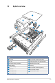
1.2 System overview 1 2 6 4 5 7 3 8 15 11 8 10 9 7 12 15 14 13 2 1 Items 1 Top cover 9 2.5-inch Hard disk drive trays (Rear) 2 Air duct 10 Full-length graphics card support bracket 3 Central processing unit (CPU) 4 CPU heatsink 5 System memory 6 PIKE card 7 Front system fans 11 Redundant power supply 12 Asset tag 13 3.5-inch Hard disk drive tray (Front) 14 3.
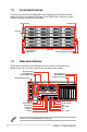
1.3 Front panel features The front panel of the RS740-E7-RS24-EG have a simple yet stylish design that features twenty-four (24) 3.5-inch Serial ATA HDD bays, two (2) USB 2.0 ports, Asset tag, steel pull handles, and easy to access buttons and LEDs. steel pull handle steel pull handle Asset tag 2 Front Thumbscrew USB 2.0 ports 1.4 HDD Trays 1 Front Thumbscrew Front Panel LEDs and buttons Rear panel features The rear panel of RS740-E7-RS24-EG features two (2) 2.
1.5 System specifications The ASUS RS740-E7-RS24-EG is a 4U barebone server system featuring the Z9PE-D1610G/DUAL server board. The server supports two Intel® LGA 2011 Intel® Xeon® processor E5-2600 plus other latest technologies through the chipsets onboard.
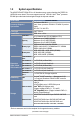
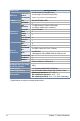
Model Name RS740-E7-RS24-EG HDD Bays I = Internal A or S will be hot-swappable Graphic VGA TPM Header USB Connectors Onboard I/O Connectors Rear I/O Connectors Fan Header SMBus Chassis Intruder Front LAN LED Serial Port Header SFP+ VGA Port External USB Port RJ-45 PS/2 Keyboard PS/2 Mouse COM port Dimension (HH x WW x DD) Net Weight Kg (CPU, DRAM & HDD not included) Power Supply Power Supply Rating Environment 24 x Hot-swap 3.5-inch HDD bays* 2 x Hot-swap 2.5-inch SSD bays (Rear) *Supports 3.
This chapter lists the key components and optional accessories for the server system.
2.1 Removing the Air Duct 2.1.1 Removing the air duct The RS740-E7-RS24-EG server system comes with a motherboard fan air duct to enable better air flow inside the motherboard while the system is running. 1 1 1 2 2.1.2 Installing the air duct Position the air duct on top of the motherboard matching the three screw holes oF the air duct to the three holes on the motherboard as indicated in the illustration below.
2.2 Installing the full-height and full-length graphics card support bracket The RS740-E7-RS24-EG server comes with a support bracket as an additional accessory when installing full-length graphics card. tab screw hole clip screw hole tab hinge Locate the full-length graphics card support bracket slots on the server.
2.3 Installing the CPU and heatsink The motherboard can support two (2) LGA2011 socket designed for the Intel® Xeon® processor E5-2600 product family. 2 1 3 6 4 5 2 1 2-4 • To prevent damage to the socket pins, do not remove the PnP cap unless you are installing a CPU. • The CPU fits in only one correct orientation.
2.4 Upgrading system memory 2.4.1 Memory configuration and population The motherboard comes with sixteen (16) Double Data Rate 3 (DDR3) Dual Inline Memory Modules (DIMM) sockets. You may install 2GB, 4GB, 8GB, 16GB, and 32GB RDIMMs or 2GB, 4GB and 8GB with ECC/ Non-ECC UDIMMs or 8GB, 16GB and 32GB LR-DIMMs into the DIMM sockets using the memory configurations in this section. GH GH AB AB FE DC FE DC • Install a DIMM beginning with either slot DIMM_A1 or DIMM_E1.
2.5 Upgrading hard disk drives 2.5.1 Front HDD installation The compact design of the server allows you to install up to twenty-four (24) 3.5-inch Serial ATA HDDs and two (2) 2.5-inch SSDs on the rear panel. 3 1 2 4 5 2.5.
2.6 Installing expansion cards The server supports installation of expansion cards via the PCIE slots if you want to upgrade your system.
2.7 Installing the ASUS PIKE RAID card The PIKE slot allows you to choose and change your preferred SAS solution easily. Install an optional ASUS PIKE RAID card based on your needs. 1 3 2 2 1 When removing the PIKE RAID card, ensure to slightly pull the metal clip to release it from the card slot.
2.8 Installing the redundant power supply modules 2.8.1 Installing the second redundant power supply module The RS740-E7-RS24-EG server comes with one (1) 800W 80Plus Platinum Redundant power supply. 2 1 2 3 2.8.
2.9 Installing the Tool-less friction rail kit 2.9.1 Installing the tool-less rack rails Front end Rack rails Rear end rear end 3 front end 4 1 2 4 rear end 1 Left Rail Right Rail 3 2 front end Steps 5-6 are optional. Perform these steps if you want to install the stopping bracket at the rear end.of the rack.
2.9.2 Mounting the server • Ensure that the rack rail cabinet and the rack posts are stable and standing firmly on a level surface. • We strongly recommend that at least two able-bodied persons perform the steps described in this guide. • We recommend the use an appropriate lifting tool or device, if necessary.
2.10 OS support list OS support list Windows® Server 2012 64-bit Windows® 8 64-bit Windows® Server 2008 Enterprise SP2 64-bit Windows® Server 2008 Enterprise R2 SP1 64-bit RedHat® Enterprise Linux AS 5.8/5.9/6.3 64-bit CentOS 5.8/5.9/6.3 64-bit Ubuntu 12.