Motherboard SABERTOOTH 990FX/GEN3 R2.
E8041 Revised Edition V2 January 2013 Copyright © 2013 ASUSTeK COMPUTER INC. All Rights Reserved. No part of this manual, including the products and software described in it, may be reproduced, transmitted, transcribed, stored in a retrieval system, or translated into any language in any form or by any means, except documentation kept by the purchaser for backup purposes, without the express written permission of ASUSTeK COMPUTER INC. (“ASUS”).
Contents Safety information...................................................................................................... vii About this guide........................................................................................................ viii SABERTOOTH 990FX/GEN3 R2.0 specifications summary..................................... x Package contents...................................................................................................... xiii Installation tools and components.....
2.3.1 2.4 2.5 2.3.2 3.2 3.3 3.4 3.5 Turning off the computer.......................................................................... 2-18 3.2.2 Advanced menu........................................................................................ 3-17 3.5.1 CPU Configuration..................................................................... 3-17 3.5.3 South Bridge Configuration........................................................ 3-21 3.5.7 3.5.8 3.5.9 iv USB Configuration................
4.2.1 4.3 Running the support DVD............................................................ 4-1 4.2.2 Obtaining the software manuals.................................................. 4-2 Software information.................................................................................. 4-3 4.3.1 AI Suite II..................................................................................... 4-3 4.3.3 Remote GO!.................................................................................
.2.1 Requirements............................................................................... 6-6 6.2.3 Installing the device drivers.......................................................... 6-7 6.2.2 6.2.4 Installing two SLI-ready graphics cards....................................... 6-6 Enabling the NVIDIA® SLI™ technology...................................... 6-8 Appendices A-1 Notices .........................................................................................................
Safety information Electrical safety • • • • • • To prevent electrical shock hazard, disconnect the power cable from the electrical outlet before relocating the system. When adding or removing devices to or from the system, ensure that the power cables for the devices are unplugged before the signal cables are connected. If possible, disconnect all power cables from the existing system before you add a device.
About this guide This user guide contains the information you need when installing and configuring the motherboard. How this guide is organized This guide contains the following parts: • • • • • • Chapter 1: Product introduction This chapter describes the features of the motherboard and the new technology it supports. It includes description of the switches, jumpers, and connectors on the motherboard.
Conventions used in this guide To ensure that you perform certain tasks properly, take note of the following symbols used throughout this manual. DANGER/WARNING: Information to prevent injury to yourself when trying to complete a task. CAUTION: Information to prevent damage to the components when trying to complete a task IMPORTANT: Instructions that you MUST follow to complete a task. . NOTE: Tips and additional information to help you complete a task.
SABERTOOTH 990FX/GEN3 R2.0 specifications summary CPU AMD® Socket AM3+ for AMD® FX series CPU up to 8-core compatible with AMD® Socket AM3 for AMD® Phenom™ II / Athlon II™ / Sempron™ 100 series processors Supports AMD® 140W CPU AMD® Cool ‘n’ Quiet Technology Supports 32nm CPU Chipset AMD® 990FX / SB950 Chipset System Bus Up to 5.2 GT/s HyperTransport™ 3.0 Memory 4 x DIMM, max. 32GB, DDR3 1866 / 1600 / 1333 / 1066 MHz, ECC, non-ECC, un-buffered memory Dual channel memory architecture * Refer to www.
SABERTOOTH 990FX/GEN3 R2.0 specifications summary USB 3 x ASMedia® USB 3.0 controllers - 2 x USB 3.0/2.0 ports at mid-board for front panel support - 4 x USB 3.0/2.0 ports at back panel [blue] AMD® SB950 Chipset - 12 x USB 2.0/1.
SABERTOOTH 990FX/GEN3 R2.0 specifications summary Back Panel I/O ports 1 x PS/2 keyboard/mouse combo port 1 x Optical S/PDIF Output port 2 x eSATA 6Gb/s ports [red] 1 x USB BIOS Flashback button 1 x LAN (RJ-45) port 4 x USB 3.0/2.0 ports [blue] 8 x USB 2.0/1.1 ports 6 x Audio jacks for 8-channel Audio I/O ports Internal I/O connectors 1 x USB 3.0/2.0 connector (supports additional 2 19-pin USB 3.0/2.0 ports [moss green]) 2 x USB 2.0/1.1 connectors (support additional 4 USB 2.0/1.
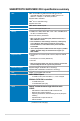
Package contents Check your motherboard package for the following items. nual User Ma ASUS SABERTOOTH 990FX/GEN3 R2.0 motherboard User manual Support DVD 4 x Serial ATA 6.0 Gb/s cables 1 x ASUS SLI™ bridge connector 1 x TUF Certification card ty r warran Five-yea 1 x ASUS Q-Shield 1 x 2-in-1 ASUS Q-Connector kit 1 x TUF Five-year warranty manual • If any of the above items is damaged or missing, contact your retailer. • The illustrated items above are for reference only.
Installation tools and components 1 bag of screws Philips (cross) screwdriver PC chassis Power supply unit AMD AM3+ CPU AMD AM3+ compatible CPU Fan DDR3 DIMM SATA hard disk drive SATA optical disc drive (optional) Graphics card (optional) The tools and components in the table above are not included in the motherboard package.
Chapter 1: Product Introduction Product introduction 1.1 Special features 1.1.1 Product highlights 1 The Ultimate Force The TUF series delivers a tough image with its unique design, and high-quality and militarystandard components. The TUF series pursues pre-eminent stability, all-around compatibility, and extreme durability.
Complete USB 3.0 Solution This motherboard offers you the strategic USB 3.0 accessibility for both the front and rear panels, allowing you to experience the convenience of the latest plug and play connectivity solution at speed up to ten times faster than USB 2.0. 1.1.2 ��������������������������������� “Ultimate COOL!” Thermal Solution TUF CeraM!X - Heatsink Coating Technology This feature offers better cooling solution for an overall improvement in system stability.
1.1.4 “Safe & Stable!” Guardian Angel ESD Guards ESD (Electrostatic Discharge) Guards provides protection against electrostatic discharges, which can damage the motherboard’s components. The ASUS exclusive Anti-Static chip and circuit design, and the I/O shield provide four times better protection and ensure the motherboard’s lifespan.
USB BIOS Flashback USB BIOS Flashback offers a hassle-free updating solution for your ultimate convenience. Install a USB storage device containing the BIOS file, press the BIOS Flashback button for about three seconds, and the UEFI BIOS is automatically updated even without entering the existing BIOS or operating system. It also allows you to regularly check for UEFI BIOS updates, and download the latest BIOS automatically. USB 3.0 Boost ASUS USB 3.
1.2 Motherboard overview 1.2.1 Before you proceed Take note of the following precautions before you install motherboard components or change any motherboard settings. • Unplug the power cord from the wall socket before touching any component.
1.2.2 Motherboard layout Chapter 1 Refer to 1.2.9 Internal connectors and 2.3.1 Rear I/O connection for more information about rear panel connectors and internal connectors.
Layout contents Page 1-36 1-8 1-34 1-9 1-25 1-30 1-29 1-30 1-38 1-37 1-26 1-33 1-27 1-32 1-28 1-38 1-35 1-31 Chapter 1 Connectors/Jumpers/Slots 1. ATX power connectors (24-pin EATXPWR, 8-pin EATX12V) 2. AM3+ CPU socket 3. CPU, chassis, and optional fan connectors (4-pin CPU_FAN, 4-pin CPU_OPT, 4-pin CHA_FAN1-4 ) 4. DDR3 DIMM slots 5. MemOK! button 6. USB 3.0 connector (20-1 pin USB3_56) 7. AMD® Serial ATA 6.0 Gb/s connectors (7-pin SATA6G_1-6 [brown]) 8. ASmedia® Serial ATA 6.
1.2.3 Central Processing Unit (CPU) The motherboard comes with an AM3+ socket designed for AMD® FX Series CPU up to 8core, also compatible with AMD® socket AM3 for AMD® Phenom™ II/Athlon™ II/ Sempron™ 100 Series Processors. Ensure that all power cables are unplugged before installing the CPU. The AM3+ socket has a different pinout design. Ensure that you use a CPU designed for the AM3+/AM3 socket. The CPU fits in only one correct orientation.
1.2.4 System memory The motherboard comes with four Double Data Rate 3 (DDR3) Dual Inline Memory Modules (DIMM) slots. A DDR3 module is notched differently from a DDR or DDR2 module. DO NOT install a DDR or DDR2 memory module to the DDR3 slot. Chapter 1 Recommended memory configurations ASUS SABERTOOTH 990FX/GEN3 R2.
Memory configurations You may install 1GB, 2GB, 4GB, 8GB, and 16GB ECC, non-ECC and unbuffered DDR3 DIMMs into the DIMM sockets. • Memory module with memory frequency higher than 2133 MHz and its corresponding timing or the loaded DRAM OC Profile is not the JEDEC memory standard. The stability and compatibility of these memory modules depend on the CPU’s capabilities and other installed devices. • You may install varying memory sizes in Channel A and Channel B.
SABERTOOTH 990FX/GEN3 R2.0 Motherboard Qualified Vendors Lists (QVL) DDR3 2400 MHz capability Vendors Part No. Size SS/ DS Chip Brand Chip NO. Timing Voltage DIMM socket support (Optional) 1 2 CORSAIR CMZ16GX3M4A2400C9R (Ver4.13)(XMP) 16GB (4x4GB) DS - - 2400 9-1111-31 1.65 • • G.SKILL F3-19200CL10Q32GBZHD(XMP) 32GB (4x8GB) DS - - 10-1212-31 1.65 • • G.SKILL F3-19200CL11Q16GBZHD(XMP) 16GB (4x4GB) DS - - 11-1111-31 1.65 • • G.
DDR3 2133 MHz capability Vendors Part No. Size SS/ DS Chip Brand Chip NO. Timing Voltage DIMM socket support (Optional) CORSAIR CMD8GX3M2A2133C9 (Ver1.5)(XMP) 8GB (2x4GB) DS - - 9-1110-27 1.5 • • CORSAIR CMT4GX3M2B2133C9 (Ver7.1)(XMP) 4GB (2x2GB) DS - - 9-9-924 1.5 • • CORSAIR CMT4GX3M2B2133C9 (XMP) 4GB (2x2GB) DS - - 9-109-27 1.5 • • G.SKILL F3-17000CL11Q264GBZLD (XMP) 64GB (8x8GB) DS - - 11-1111-30 1.5 • • • G.
DDR3 2000 MHz capability Vendors Part No. Size SS/ DS Chip Brand Chip NO. Timing Voltage DIMM socket support (Optional) 1 2 4 AEXEA AXA3ES2G2000LG28V (XMP) 2GB DS - - - 1.65 • • • AEXEA AXA3ES4GK2000LG28V (XMP) 4GB (2x2GB) DS - - - 1.65 • • • Apacer 78.AAGD5.9KD (XMP) 6GB (3x2GB) DS - - 9-9-9-27 - • • Asint SLA302G08-ML2HB (XMP) 4GB DS Hynix H5TQ2G83BFRH9C 9-9-9-27 - • • G.SKILL F3-16000CL9D-4GBRH (XMP) 4GB (2x2GB) DS - - 9-9-9-24 1.65 • • G.
DDR3 1866 MHz capability Chapter 1 1-14 Vendors Part No. Size SS/ DS Chip Brand Chip NO. Timing Voltage DIMM socket support (Optional) 1 2 4 CORSAIR CMD16GX3M4A1866C9 (Ver4.13)(XMP) 16GB (4x4GB) DS - - 9-10-9-27 1.5 • • • CORSAIR CMD16GX3M4A1866C9 (Ver8.16)(XMP) 16GB (4x4GB) DS - - 9-10-9-27 1.5 • • CORSAIR CMD8GX3M2A1866C9 (Ver4.13)(XMP) 8GB (2x4GB) DS - - - 1.5 • • • CORSAIR CMD8GX3M2A1866C9 (Ver8.16)(XMP) 8GB (2x4GB) DS - - 9-10-9-27 1.
DDR3 1800 MHz capability Vendors Part No. Size SS/ DS Chip Brand Chip NO. Timing Voltage G.SKILL F3-14400CL9D4GBRL(XMP) 4GB (2x2GB) DS - - 9-9-9-24 1.6 DIMM socket support (Optional) 1 2 • 4 • • DDR3 1600 MHz capability Vendors Part No. Size SS/ DS Chip Brand Chip NO. Timing Voltage DIMM socket support (Optional) 1 2 4 AMD AE32G1609U1-U 2GB SS AMD 23EY4587MB6H - 1.5 • • • AMD AP38G1608U2K (XMP) 8GB (2x4GB) DS - - 9-9-9-28 1.65 • • Apacer 78.B1GE3.
DDR3 1600 MHz capability Chapter 1 Vendors Part No. Size SS/ DS Chip Brand Chip NO. Timing Voltage DIMM socket support (Optional) 1 2 4 CENTURY CD4G-D3U1600 4GB DS ELPIDA EDJ2108BDBGGN-F - 1.5 • • • CENTURY CD4G-D3U1600 4GB DS Hynix H5TQ2G83CFRPBC - 1.5 • • • CENTURY CD8G-D3U1600 8GB DS ELPIDA EDJ4208BBBGGN-F - 1.5 • • • CENTURY CD8G-D3U1600 8GB DS Hynix H5TQ4G83MFRPBC - 1.5 • • • CORSAIR CMD16GX3M2A1600C9 (Ver8.
DDR3 1600 MHz capability Vendors Part No. Size SS/ DS Chip Brand Chip NO. Timing Voltage DIMM socket support (Optional) 1 2 4 Crucial BL12864BN1608.8FF (XMP) 2GB (2x1GB) SS - - 8-8-8-24 1.65 • • • Crucial BLT4G3D1608DT1TX0.16FM (XMP) 4GB DS - - 8-8-8-24 1.
DDR3 1600 MHz capability Chapter 1 Vendors Part No. Size SS/ DS Chip Brand Chip NO. Timing Voltage DIMM socket support (Optional) 1 2 4 KINGSTON KHX1600C9D3LK2/ 4GX (XMP) 4GB (2x2GB) DS - - - 1.35 • • • KINGSTON KHX1600C9D3LK2/ 8GX (XMP) 8GB (2x4GB) DS - - 9-9-9-24 1.35 • • • KINGSTON KHX1600C9D3P1K2/ 8G 8GB (2x4GB) DS - - 9 1.5 • • • KINGSTON KHX1600C9D3T1BK3/ 12GX (XMP) 12GB (3x4GB) DS - - 9 1.
DDR3 1600 MHz capability Vendors Part No. Size SS/ DS Chip Brand Chip NO. Timing Voltage DIMM socket support (Optional) 1 2 4 SanMax SMD-4G68HP-16KZ 4GB DS Hynix H5TQ2G83BFRPBC - 1.5 • • • SanMax SMD-4G68NG-16KK 4GB DS ELPIDA J2108BDBG-GN-F - - • • • Silicon Power SP002GBLTU160V02 (XMP) 2GB SS SPOWER 20YT5NG 9-1111-28 1.5 • • • Silicon Power SP004GBLTU160V02 (XMP) 4GB DS SPOWER 20YT5NG 9-9-9-24 1.
DDR3 1333 MHz capability Chapter 1 Vendors Part No. Size SS/ DS Chip Brand Chip NO.
DDR3 1333 MHz capability Part No. Size SS/ DS Chip Brand Chip NO.
DDR3 1333 MHz capability Vendors Part No. Size SS/ DS Chip Brand Chip NO.
1.2.5 Expansion slots Unplug the power cord before adding or removing expansion cards. Failure to do so may cause you physical injury and damage motherboard components. Slot No. 1 2 3 4 PCIe 3.0 x16_1 slot (single at x16, dual at x16/x16, triple at x16/x8/x8 mode) PCIe 2.0 x16_2 slot PCIe 3.0 x16_3 slot PCI slot PCIe 3.0 x16_4 slot Chapter 1 5 Slot Description ASUS SABERTOOTH 990FX/GEN3 R2.
PCI Express operating mode VGA configuration PCIe 3.0_x16_1 PCIe 2.0_x16_2 PCIe 3.0x16_3 PCIe 3.0x16_4 Single or Dual VGA/PCIe card x16 (Recommend for single VGA) x16 x16 N/A 3-way SLI x16 x16 x8 x8 • In single VGA card mode, use the PCIe 3.0 x16_1 slot (beige) for a PCI Express x16 graphics card to get better performance. • In CrossFireX™ or SLI™ mode, use the PCIe 3.0 x16_1 and PCIe 3.0 x16_3 slots for PCI Express x16 graphics cards to get better performance.
1.2.6 Onboard buttons Onboard buttons allow you to fine-tune performance when working on a bare or opencase system. This is ideal for overclockers and gamers who continually change settings to enhance system performance. 1. MemOK! button Installing DIMMs that are not compatible with the motherboard may cause system boot failure, and the DRAM_LED near the MemOK! switch lights continuously.
2. DirectKey button This feature allows your system to go to the BIOS Setup program with the press of a button. With DirectKey, you can enter the BIOS anytime without having to press the key during POST. It also allows you to turn on or turn off your system and conveniently enter the BIOS during boot-up. Ensure to save your data before using the DirectKey button. • When the system is on and you press the DirectKey button, your system will shut down.
1.2.7 1. Jumpers Clear RTC RAM (3-pin CLRTC) This jumper allows you to clear the Real Time Clock (RTC) RAM in CMOS. You can clear the CMOS memory of date, time, and system setup parameters by erasing the CMOS RTC RAM data. The onboard button cell battery powers the RAM data in CMOS, which include system setup information such as system passwords. To erase the RTC RAM: 1. Turn OFF the computer and unplug the power cord. 2. Move the jumper cap from pins 1-2 (default) to pins 2-3.
1.2.8 1. 2. Onboard LEDs POST State LEDs The POST State LEDs provide the status of these key components during POST (Power-On-Self Test): CPU, memory modules, VGA card, and hard disk drives. If an error is found, the critical component’s LED stays lit up until the problem is solved. Standby Power LED The motherboard comes with a standby power LED. The green LED lights up to indicate that the system is ON, in sleep mode, or in soft‑off mode.
1.2.9 1. Internal connectors AMD® Serial ATA 6.0 Gb/s connectors (7-pin SATA6G_1-6 [brown]) These connectors connect to Serial ATA 6.0 Gb/s hard disk drives via Serial ATA 6.0 Gb/s signal cables. • These connectors are set to [AHCI Mode] by default. If you intend to create a Serial ATA RAID set using these connectors, set the SATA Mode item in the BIOS to [RAID Mode]. Refer to section 3.5.4 SATA Configuration for details. • Before creating a RAID set, refer to section 5.
2. 3. ASMedia® Serial ATA 6.0 Gb/s connectors (7-pin SATA6G_E1-2 [gray]) These connectors connect to Serial ATA 6.0 Gb/s hard disk drives via Serial ATA 6.0 Gb/s signal cables. USB 3.0 connector (20-1 pin USB3_56) This connector is for the additional USB 3.0 ports, and complies with the USB 3.0 specificaton that supports up to 480 MBps connection speed. If the USB 3.0 front panel cable is available from your system chassis, with this USB 3.0 connector, you can have a front panel USB 3.0 solution.
4. Digital audio connector (4-1 pin SPDIF_OUT) This connector is for an additional Sony/Philips Digital Interface (S/PDIF) port. Connect the S/PDIF Out module cable to this connector, then install the module to a slot opening at the back of the system chassis. Chapter 1 The S/PDIF module is purchased separately. ASUS SABERTOOTH 990FX/GEN3 R2.
5. USB 2.0 connectors (10-1 pin USB1314, USB1112) These connectors are for USB 2.0 ports. Connect the USB module cable to any of these connectors, then install the module to a slot opening at the back of the system chassis. These USB connectors comply with USB 2.0 specification that supports up to 48 MBps connection speed. Never connect a 1394 cable to the USB connectors.
6. Serial port connector (10-1 pin COM1) This connector is for a serial (COM) port. Connect the serial port module cable to this connector, then install the module to a slot opening at the back of the system chassis. Chapter 1 The COM module is purchased separately. ASUS SABERTOOTH 990FX/GEN3 R2.
7. CPU and chassis fan connectors (4-pin CPU_FAN, 4-pin CPU_OPT, 4-pin CHA_FAN1-4) Connect the fan cables to the fan connectors on the motherboard, ensuring that the black wire of each cable matches the ground pin of the connector. DO NOT forget to connect the fan cables to the fan connectors. Insufficient air flow inside the system may damage the motherboard components.
8. Front panel audio connector (10-1 pin AAFP) This connector is for a chassis-mounted front panel audio I/O module that supports either HD Audio or legacy AC`97 audio standard. Connect one end of the front panel audio I/O module cable to this connector. • ��������������������������������������������������������������������������������� We recommend that you connect a high-definition front panel audio module to this connector to avail of the motherboard’s high-definition audio capability.
9. ATX power connectors (24-pin EATXPWR, 8-pin EATX12V) These connectors are for ATX power supply plugs. The power supply plugs are designed to fit these connectors in only one orientation. Find the proper orientation and push down firmly until the connectors completely fit. • ����������������������������������������������������������������������������� For a fully configured system, we recommend that you use a power supply unit (PSU) that complies with ATX 12 V Specification 2.
10. • • • • This connector supports several chassis-mounted functions. System power LED (2-pin PLED) This 2-pin connector is for the system power LED. Connect the chassis power LED cable to this connector. The system power LED lights up when you turn on the system power, and blinks when the system is in sleep mode. Hard disk drive activity LED (2-pin IDE_LED) This 2-pin connector is for the HDD Activity LED. Connect the HDD Activity LED cable to this connector.
11. 12. TPM connector (20-1 pin TPM) This connector supports a Trusted Platform Module (TPM) system, which securely store keys, digital certificates, passwords and data. A TPM system also helps enhance network security, protect digital identities, and ensures platform integrity. Direct Connector (2-pin DRCT) This connector is for the chassis-mounted button that supports the DirectKey function. Connect the button cable that supports DirectKey, from the chassis to this connector on the motherboard.
Chapter 2: Basic Installation Basic Installation 2.1 Building your PC system 2.1.1 Motherboard installation 2 The diagrams in this section are for reference only. The motherboard layout may vary with models, but the installation steps are the same for all models. Install the ASUS Q-Shield to the chassis rear I/O panel. Chapter 2 1. ASUS SABERTOOTH 990FX/GEN3 R2.
2. Place the motherboard into the chassis, ensuring that its rear I/O ports are aligned to the chassis’ rear I/O panel.
Place nine screws into the holes indicated by circles to secure the motherboard to the chassis. Chapter 2 3. DO NOT overtighten the screws! Doing so can damage the motherboard. ASUS SABERTOOTH 990FX/GEN3 R2.
2.1.2 CPU installation The AMD AM3+ socket is compatible with AMD AM3+ and AM3 processors. Ensure you use a CPU designed for the AM3+ socket. The CPU fits in only one correct orientation.
2.1.3 CPU heatsink and fan assembly installation Apply the Thermal Interface Material to the CPU heatsink and CPU before you install the heatsink and fan if necessary. To install the CPU heatsink and fan assembly Chapter 2 1 ASUS SABERTOOTH 990FX/GEN3 R2.
2 3 4 5 Chapter 2 2-6 Chapter 2: Getting started
2.1.4 DIMM installation 1 2 3 To remove a DIMM B ASUS SABERTOOTH 990FX/GEN3 R2.
2.1.
2.1.6 SATA device connection 1 OR 2 Chapter 2 OR ASUS SABERTOOTH 990FX/GEN3 R2.
2.1.7 Front I/O Connector To install ASUS Q-Connector 2 1 IDE_LED+ IDE_LED- PWR Ground Reset Ground IDE_LED R POWE SW RESET SW To install USB 2.0 connector To install front panel audio connector AAFP USB 2.0 To install USB 3.0 connector Chapter 2 USB 3.
2.1.8 Expansion Card installation To install PCIe x16 cards Chapter 2 To install PCIe x1 cards ASUS SABERTOOTH 990FX/GEN3 R2.
2.2 BIOS update utility USB BIOS Flashback USB BIOS Flashback allows you to easily update the BIOS without entering the existing BIOS or operating system. Simply insert a USB storage device to the USB port, press the USB BIOS Flashback button for three seconds, and the BIOS is updated automatically. To use USB BIOS Flashback: 1. Place the bundled support DVD to the optical drive and install the USB BIOS Flashback Wizard. Follow the onscreen instructions to complete the installation.
2.3 Motherboard rear and audio connections 2.3.1 Rear I/O connection Rear panel connectors 1. PS/2 Combo port 7. USB 2.0 ports 3, 4, 5, and 6 2. USB 3.0 ports 1 and 2 8. USB 3.0 ports 3 and 4 3. LAN (RJ-45) port* 9. USB BIOS Flashback button 4. USB 2.0 ports 7 and 8 10. USB 2.0 ports 1 and 2 5. Optical S/PDIF Out port 11. Audio I/O ports** 6. External SATA ports ASUS SABERTOOTH 990FX/GEN3 R2.
• DO NOT insert a different connector to the external SATA port. • DO NOT connect a keyboard/mouse to any USB 3.0 port when installing Windows® operating system. • Due to USB 3.0 controller limitation, USB 3.0 devices can only be used under Windows® OS environment and after the USB 3.0 driver installation. • USB 3.0 devices can only be used as data storage only. • We strongly recommend that you connect USB 3.0 devices to USB 3.0 ports for faster and better performance for your USB 3.0 devices.
2.3.2 Audio I/O connections Audio I/O ports Connect to Headphone and Mic Connect to Stereo Speakers Chapter 2 Connect to 2.1 channel Speakers ASUS SABERTOOTH 990FX/GEN3 R2.
Connect to 4.1 channel Speakers Connect to 5.
Connect to 7.1 channel Speakers 2.4 Starting up for the first time 1. After making all the connections, replace the system case cover. 2. Ensure that all switches are off. 3. Connect the power cord to the power connector at the back of the system chassis. 4. Connect the power cord to a power outlet that is equipped with a surge protector. 5. Turn on the devices in the following order: 6. a. Monitor b. External SCSI devices (starting with the last device on the chain) c.
BIOS Beep Description One short beep VGA detected Quick boot set to disabled No keyboard detected 7. 2.5 One continuous beep followed by two short beeps then a pause (repeated) No memory detected One continuous beep followed by three short beeps No VGA detected One continuous beep followed by four short beeps Hardware component failure At power on, hold down the key to enter the BIOS Setup. Follow the instructions in Chapter 3.
Chapter 3: BIOS setup BIOS setup 3.1 Knowing BIOS 3 The new ASUS UEFI BIOS is a Unified Extensible Interface that complies with UEFI architecture, offering a user-friendly interface that goes beyond the traditional keyboardonly BIOS controls to enable a more flexible and convenient mouse input. You can easily navigate the new UEFI BIOS with the same smoothness as your operating system. The term “BIOS” in this user manual refers to “UEFI BIOS” unless otherwise specified.
3.2 BIOS setup program Use the BIOS Setup to update the BIOS or configure its parameters. The BIOS screen include navigation keys and brief onscreen help to guide you in using the BIOS Setup program. Entering BIOS at startup To enter BIOS Setup at startup: • Press during the Power-On Self Test (POST). If you do not press , POST continues with its routines. Entering BIOS Setup after POST To enter BIOS Setup after POST: • Press ++ simultaneously.
3.2.1 EZ Mode By default, the EZ Mode screen appears when you enter the BIOS setup program. The EZ Mode provides you an overview of the basic system information, and allows you to select the display language, system performance mode and boot device priority. To access the Advanced Mode, click Exit/Advanced Mode, then select Advanced Mode or press hot key for the advanced BIOS settings. The default screen for entering the BIOS setup program can be changed. Refer to the Setup Mode item in section 3.
3.2.2 Advanced Mode The Advanced Mode provides advanced options for experienced end-users to configure the BIOS settings. The figure below shows an example of the Advanced Mode. Refer to the following sections for the detailed configurations. To access the Advanced Mode, click Exit, then select Advanced Mode or press F7 hotkey.
Menu items The highlighted item on the menu bar displays the specific items for that menu. For example, selecting Main shows the Main menu items. The other items (Ai Tweaker, Advanced, Monitor, Boot, Tool, and Exit) on the menu bar have their respective menu items. Back button This button appears when entering a submenu. Press or use the USB mouse to click this button to return to the previous menu screen.
3.3 Main menu The Main menu screen appears when you enter the Advanced Mode of the BIOS Setup program. The Main menu provides you an overview of the basic system information, and allows you to set the system date, time, language, and security settings.
Administrator Password If you have set an administrator password, we recommend that you enter the administrator password for accessing the system. Otherwise, you might be able to see or change only selected fields in the BIOS setup program. To set an administrator password: 1. Select the Administrator Password item and press . 2. From the Create New Password box, key in a password, then press . 3. Confirm the password when prompted. To change an administrator password: 1.
To change a user password: 1. Select the User Password item and press . 2. From the Enter Current Password box, key in the current password, then press . 3. From the Create New Password box, key in a new password, then press . 4. Confirm the password when prompted. To clear the user password, follow the same steps as in changing a user password, but press when prompted to create/confirm the password.
Ai Overclock Tuner [Auto] Allows you to select the CPU overclocking options to achieve the desired CPU internal frequency. Select any of these preset overclocking configuration options: [Auto] Loads the optimal settings for the system. [D.O.C.P.] Allows you to select a DRAM voltage. [Manual] Allows you to individually set overclocking parameters. The following item appears only when you set the Ai Overclocking Tuner to [Manual]. CPU Bus Frequency [Auto] Allows you to set the CPU and VGA frequency.
CPU Spread Spectrum [Auto] [Auto] Automatic configuration. [Enabled] Sets to [Enabled] for EMI control. [Disabled] Enhances the BCLK overclocking ability. PCIe Spread Spectrum [Auto] [Auto] Automatic configuration. [Enabled] Sets to [Enabled] for EMI control. [Disabled] Enhances the PCIE overclocking ability EPU Power Saving Mode [Disabled] Allows you to enable or disable the EPU power saving function.
DRAM READ to PRE Time [Auto] Configuration options: [Auto] [4] – [10] DRAM RAS# to RAS# Delay [Auto] Configuration options: [Auto] [1] – [9] DRAM WRITE to READ Delay [Auto] Configuration options: [Auto] [4] – [9] DRAM CAS# Write Latency [Auto] Configuration options: [Auto] [5] – [12] DRAM WRITE Recovery Time [Auto] Configuration options: [Auto] [5] [6] [7] [8] [10] [12] [14] ��������� [16] DRAM REF Cycle Time [Auto] Configuration options: [Auto] [90ns] [110ns] [160ns] [300ns] [350ns] DRAM Row Cy
DRAM Driving Control Allows you to set the primary, secondary, and tertiary memory timings. DCT0 Information CKE drive strength [Auto] Configuration options: [Auto] [1x] [1.25x] [1.5x] [2x] CS/ODT drive strength [Auto] Configuration options: [Auto] [1x] [1.25x] [1.5x] [2x] ADDR/CMD drive strength [Auto] Configuration options: [Auto] [1x] [1.25x] [1.5x] [2x] MEMCLK drive strength [Auto] Configuration options: [Auto] [0.75x] [1x] [1.25x] [1.
DIGI+ Power Control CPU Load-Line Calibration [Auto] Load-line is defined by AMD VRM specification and affects CPU voltage. The CPU working voltage will decrease proportionally to CPU loading. Higher value gets a higher voltage and better overclocking performance, but increases the CPU and VRM thermal conditions. This item allows you to adjust the voltage range from the following percentages to boost the system performance: 0% (Regular), 25% (Medium), 50% (High), 75% (Ultra High) and 100% (Extreme).
Manual Adjustment [Fast] This item appears only when you set the CPU Power Phase Control item to [Manual Adjustment]. Configuration options: [Ultra Fast] [Fast] [Medium] [Regular] CPU Voltage Frequency [Auto] Frequency switching affects the VRM transient response, and the thermal component. Higher frequency gets quicker transient response. Configuration options: [Auto] [Manual] DO NOT remove the thermal module when switching to Manual Mode. The thermal conditions should be monitored.
CPU Power Thermal Control [130] A higher temperature brings a wider CPU power thermal range and extends the overclocking tolerance to enlarge the O.C. potential. Use the <+> and <-> keys to adjust the value. The values range from 130 to 151. DO NOT remove the thermal module. The thermal conditions should be monitored. DRAM Current Capability [100%] A higher value brings a wider total power range, and extends the overclocking range simultaneously.
CPU/NB Offset Mode Sign [+] [+] To offset the voltage by a positive value. [–] To offset the voltage by a negative value. CPU/NB Offset Voltage [Auto] This item appears only when you set the CPU & NB Voltage item to [Offset Mode] and allows you to set the CPU/NB Offset voltage. The values range from 0.00625V to 0.70000V with a 0.00625V interval. CPU VDDA Voltage [Auto] Allows you to set the CPU VDDA voltage. The values range from 2.20000V to 2.80000V with a 0.00625V interval.
3.5 Advanced menu The Advanced menu items allow you to change the settings for the CPU and other system devices. Be cautious when changing the settings of the Advanced menu items. Incorrect field values can cause the system to malfunction.
UEFI BIOS Utility - Advanced Mode Ai Tweaker Main Back Advanced Exit Monitor Boot Tool Advanced\ CPU Configuration > CPU Configuration Enabled/Disabled the generation of ACPI _PPC, _PSS, and _PCT objects.
3.5.
ECC Mode [Enabled] Allows you to enable or disable the Error Correcting Code (ECC) Mode. Configuration options: [Enabled] [Disabled] Power Down Enable [Disabled] Allows you to enable or disable DDR power down mode. Configuration options: [Enabled] [Disabled] Memory Hole Remapping [Enabled] Allows you to enable or disable Memory Hole Remapping function. Configuration options: [Enabled] [Disabled] DCT Unganged Mode [Enabled] Allows you to select unganged DRAM mode (64-bit width).
3.5.3 South Bridge Configuration UEFI BIOS Utility - Advanced Mode Ai Tweaker Main Back Exit Monitor Advanced Boot Tool Advanced\ South Bridge > HPET Enabled HPET TIMER HPET [Enabled] Allows you to enable or disable the High Precision Event Timer (HPET). Configuration options: [Enabled] [Disabled] 3.5.4 SATA Configuration While entering Setup, the BIOS automatically detects the presence of SATA devices.
SB SATA Configuration This item alows you to set the SATA configuration. OnChip SATA Channel [Enabled] Allows you to enable or disable the Serial ATA channel. Configuration options: [Enabled] [Disabled] The following items appear only when you set the OnChip SATA Channel to [Enabled]. SATA Port1 - Port 4 [AHCI] Allows you to set the SATA configuration. [IDE] Set to [IDE] when you want to use the Serial ATA hard disk drives as Parallel ATA physical storage devices.
3.5.5 USB Configuration The items in this menu allow you to change the USB-related features. UEFI BIOS Utility - Advanced Mode Ai Tweaker Main Back Advanced Exit Monitor Boot Tool Advanced\ USB Configuration > USB Configuration USB Devices: 1 Keyboard, 1 Mouse, 2 Hubs Legacy USB Support Enabled Legacy USB3.0 Support Enabled EHCI Hand-off Disabled Enables Legacy USB support. AUTO option disables legacy support if no USB devices are connected.
3.5.6 CPU Core On/Off Function UEFI BIOS Utility - Advanced Mode Ai Tweaker Main Back Advanced Exit Monitor Boot Tool Advanced\ CPU Core On/Off Function > CPU Core Activation Auto Let User turn off core except core 1, user can turn of 2nd, 3rd, 4th, 5th, etc core manually CPU Core Activation [Auto] Allows you to automatically or manually activate the CPU cores. Configuration options: [Auto] [Manual] The following items appear only when you set the CPU Core Activation to [Manual].
ASM1061 Storage Controller (Rear) [Enabled] Allows you to select the ASM1061 storage controller operating mode. [Disabled] [Enabled] Disables the ASM1061 storage controller. Enables the ASM1061 storage controller. ASM1061 Storage Controller (Front) [Enabled] Allows you to select the ASM1061 storage controller operating mode. [Disabled] [Enabled] Disables the ASM1061 storage controller. Enables the ASM1061 storage controller. ASmedia USB 3.
SB HD Azalia Configuration The sub-items in this menu allow you to set the SB HD Azalia configuration. HD Audio Azalia Device [Enabled] [Enabled] Enables the HD Audio Device. [Disabled] Disables the controller. The following two items appear only when you set the HD Azalia Audio Device item to [Enabled].
Power On By PME Device [Disabled] [Disabled] Disables the PME device to generate a wake-on-LAN feature of the Realtek LAN device. [Enabled] Enables the PME device to generate a wake-on-LAN feature of the Realtek LAN device. Power On By Ring [Disabled] [Disabled] Disables Wake-On-Ring from generating a wake event. [Enabled] Enables Wake-On-Ring to generate a wake event. Power On By RTC [Disabled] [Disabled] Disables RTC to generate a wake event.
3.6 Monitor menu The Monitor menu displays the system temperature/power status, and allows you to change the fan settings. Scroll down to display the other BIOS items. UEFI BIOS Utility - Advanced Mode Main Ai Tweaker Exit Advanced Monitor Boot Tool CPU Temperature �������������� +73ºC / +163ºF MB Temperature +31ºC / +87ºF VCORE Voltage +1.452 V 3.3V Voltage +3.312 V 5V Voltage +5.080 V 12V Voltage +12.192 V VDDA2.5V Voltage +2.
CPU Fan Speed Low Limit [600 RPM] This item appears only when you enable the CPU Q-Fan Control feature and allows you to disable or set the CPU fan warning speed. Configuration options: [Ignore] [200 RPM] [300 RPM] [400 RPM] [500 RPM] [600 RPM] CPU Fan Profile [Standard] This item appears only when you enable the CPU Q-Fan Control feature and allows you to set the appropriate performance level of the CPU fan.
Chassis Fan 1/4 Profile [Standard] This item appears only when you enable the Chassis Q-Fan Control feature and allows you to set the appropriate performance level of the chassis fan. [Standard] Sets to [Standard] to make the chassis fan automatically adjust depending on the chassis temperature. [Silent] [Turbo] [Manual] Sets to [Silent] to minimize the fan speed for quiet chassis fan operation. Sets to [Turbo] to achieve maximum chassis fan speed.
3.7 Boot menu The Boot menu items allow you to change the system boot options. UEFI BIOS Utility - Advanced Mode Ai Tweaker Main Exit Advanced Monitor Boot Configuration Fast Boot Enabled USB Support Partial In... PS/2 Keyboard and Mouse Support Disabled Network Stack Driver Support Boot Tool Select [Enable] to accelerate the boot speed. Select [Disable] to go back to normal boot. Disabled Next Boot after AC Power Loss Normal Boot DirectKey [Go to BIOS...
PS/2 Keyboard and Mouse Support [Auto] Select any of these settings when PS/2 keyboard and mouse are installed. These settings only apply when Fast Boot is enabled. [Auto] For a faster POST time, PS/2 devices will only be available when the system boots up or rebooted when the PS/2 devices have not been reconnected or changed. If you disconnect or change PS/2 devices before restarting the system, PS/2 devices will not be available and BIOS setup program will not be accessible via PS/2 devices.
CSM (Compatibility Support Module) Allows you to configure the CSM (Compatibility Support Module) items to fully support the various VGA, bootable devices and add-on devices for better compatibility. Launch CSM [Auto] [Auto] [Enabled] [Disabled] The system automatically detects the bootable devices and the addon devices. For better compatibility, enable the CSM to fully support the non-UEFI driver add-on devices or the Windows® UEFI mode.
Secure Boot Allows you to configure the Windows® Secure Boot settings and manage its keys to protect the system from unauthorized access and malwares during POST. OS Type [Windows UEFI mode] Allows you to select your installed operating system. [Windows UEFI mode] Executes the Microsoft® Secure Boot check. Only select this option when booting on Windows® UEFI mode or other Microsoft® Secure Boot compliant OS.
PK Management The Platform Key (PK) locks and secures the firmware from any permissible changes. The system verifies the PK before your system enters the OS. Load PK from File Allows you to load the downloaded PK from a USB storage device. Copy PK to File Allows you to store the PK to a USB storage device. Delete PK Allows you to delete the PK from your system. Once the PK is deleted, all the system’s Secure Boot keys will not be active.
Append db from file Allows you to load the additional db from a storage device so that more images can be loaded securely. Delete the db Allows you to delete the db file from your system. Configuration options: [Yes] [No] The db file must be formatted as a UEFI variable structure with time-based authenticated variable. dbx Management The dbx (Revoked Signature database) lists the forbidden images of db items that are no longer trusted and cannot be loaded.
3.8 Tools menu The Tools menu items allow you to configure options for special functions. Select an item then press to display the submenu. UEFI BIOS Utility - Advanced Mode Ai Tweaker Main Advanced > ASUS EZ Flash 2 Utility Exit Monitor Boot Tool Be used to update BIOS > ASUS SPD Information > ASUS O.C. Profile 3.8.1 ASUS EZ Flash 2 Utility Allows you to run ASUS EZ Flash 2. When you press , a confirmation message appears.
3.8.2 ASUS SPD Information Allows you to view the DRAM SPD information.
3.8.3 ASUS O.C. Profile This item allows you to store or load multiple BIOS settings. UEFI BIOS Utility - Advanced Mode Ai Tweaker Main Back Exit Advanced Monitor O.C. Profile Configuration Setup Setup Setup Setup Setup Setup Setup Setup Profile Profile Profile Profile Profile Profile Profile Profile Boot Tool Tool\ ASUS O.C.
3.9 Exit menu The Exit menu items allow you to load the optimal default values for the BIOS items, and save or discard your changes to the BIOS items. You can access the EZ Mode from the Exit menu. Exit Load Optimized Defaults Save Changes & Reset Discard Changes & Exit ASUS EZ Mode Launch EFI Shell from filesystem device Load Optimized Defaults This option allows you to load the default values for each of the parameters on the Setup menus.
3.10 Updating BIOS The ASUS website publishes the latest BIOS versions to provide enhancements on system stability, compatibility, or performance. However, BIOS updating is potentially risky. If there is no problem using the current version of BIOS, DO NOT manually update the BIOS. Inappropriate BIOS updating may result in the system’s failure to boot. Carefully follow the instructions of this chapter to update your BIOS if necessary. Visit the ASUS website (www.asus.
Launching ASUS Update To launch ASUS Update, click Update > ASUS Update on the AI Suite II main menu bar. Quit all Windows® applications before you update the BIOS using this utility. Updating the BIOS through the Internet To update the BIOS through the Internet: 1. From the ASUS Update screen, select Update BIOS from Internet, and then click Next. 2. Select the ASUS FTP site nearest you to avoid network traffic.
Updating the BIOS through a BIOS file 1. From the ASUS Update screen, select Update BIOS from file, and then click Next. 2. Locate the BIOS file and click Next. 3. You can decide whether to change the BIOS boot logo. Click Yes if you want to change the boot logo or No to continue. 4. Follow the onscreen instructions to complete the update process.
3.10.2 ASUS EZ Flash 2 ASUS EZ Flash 2 allows you to update the BIOS without having to use a bootable floppy disk or an OS‑based utility. Before you start using this utility, download the latest BIOS from the ASUS website at www.asus.com. To update the BIOS using EZ Flash 2: 1. Insert the USB flash disk that contains the latest BIOS file to the USB port. 2. Enter the Advanced Mode of the BIOS setup program. Go to the Tool menu to select ASUS EZ Flash Utility and press to enable it.
• ������������������������������������������������������������������������������������� This function can support devices such as a USB flash disk with FAT 32/16 format and single partition only. • ������������������������������������������������������������������������������� DO NOT shut down or reset the system while updating the BIOS to prevent system boot failure! Ensure to load the BIOS default settings to ensure system compatibility and stability.
Booting the system in DOS environment 1. Insert the USB flash drive with the latest BIOS file and BIOS Updater to the USB port. 2. Boot your computer. When the ASUS Logo appears, press to show the BIOS Boot Device Select Menu. Insert the support DVD into the optical drive and select the optical drive as the boot device.
2. The BIOS Updater screen appears as below. ASUSTek BIOS Updater for DOS V1.30 [2012/12/22] FLASH TYPE: MX1C 25L1065A Current ROM Update ROM BOARD: SABERTOOTH 990FX/GEN3 R2.0 BOARD: UNKNOWN VER: 0204 VER: UNKNOWN DATE: 09/15/2012 DATE: UNKNOWN PATH: A:\ A: ST990R20.CAP Note [Enter] Select or Load [Up/Down/Home/End] Move 3.
4. Select Yes and press . When BIOS update is done, press to exit BIOS Updater. Restart your computer. DO NOT shut down or reset the system while updating the BIOS to prevent system boot failure! • ����������������������������������������������������������������������������������� For BIOS Updater version 1.04 or later, the utility automatically exits to the DOS prompt after updating BIOS.
Chapter 4: Software support Software support 4.1 Installing an operating system • 4 This motherboard supports Windows® XP/ 64-bit XP/ 7 / 64-bit 7 operating systems (OS). • ����������������������������������������������������������������������������������� Motherboard settings and hardware options vary. Use the setup procedures presented in this chapter for reference only. Refer to your OS documentation for detailed information.
4.2.2 Obtaining the software manuals The software manuals are included in the support DVD. Follow the instructions below to get the necessary software manuals. The software manual files are in Portable Document Format (PDF). Install the Adobe® Acrobat® Reader from the Utilities menu before opening the files. 1. Click Manual tab. Click ASUS Motherboard Utility Guide from the manual list on the left. 2. The Manual folder of the support DVD appears. Double-click the folder of your selected software. 3.
4.3 Software information 4.3.1 AI Suite II Most of the applications in the support DVD have wizards that will conveniently guide you through the installation. View the online help or readme file that came with the software application for more information. AI Suite II is an all-in-one interface that integrates several ASUS utilities and allows users to launch and operate these utilities simultaneously. Installing AI Suite II To install AI Suite II on your computer: 1.
4.3.2 ASUS TUF Thermal Radar TUF Thermal Radar monitors the critical components in real-time and automatically adjusts fan speeds for system stability. Its interface provides you with sensors for various components, allowing you to monitor the components individually. It automatically adjusts fan speeds based on your selected or customized fan profile for each component, keeping the system stable and cool.
Configuring system fan settings TUF Thermal Radar’s preset fan profiles automatically adjusts the fan speeds based on the ambient temperature and the system’s load. It also allows you to customize the fan speeds to achieve a quiet and cool environment for the system. Loading the preset fan profiles To load the preset fan profiles: Click screen. or from the function list on the bottom of the Thermal Radar main 2. Click the fan that you want to assign a preset fan profile to. 3.
Configuring user-customizable fan settings You can customize the fan speed to meet different computing and environment needs. To customize the fan speed: 1. Select User in the Profile Name dropdown list. 2. Drag the control points on the fan speed curve to set the fan speed percentage. 3. Click Apply. You can also assign the specific component that Thermal Radar will monitor and dynamically adjust the fan speeds in real-time when the temperature reaches a certain degree.
4. If you are not sure how to choose the proper components to monitor and the percentage to adjust, click Auto and have Thermal Radar do the recommended settings for you. Click Apply for the setting to take effect. Configuring Chassis Fan 4 settings Allows you to set a profile to your CHA_FAN4. To select the CHA_FAN4 setting: 1. Click . 2. Click the setting that you want to apply for the CHA_FAN4. 3. If you select User setting, adjust the slider to set the RPM percentage. 3.
4.3.3 Remote GO! Connect your computer to a wireless network and use Remote GO! to wirelessly stream media files to DLNA devices. It allows you to remotely control and access your computer using your mobile device, and easily transfer files between your computer and mobile device. • Remote GO! is supported only on Windows® 7. • All devices using the Remote GO! functions must be in the same network. Using Remote GO! To launch Remote GO!, click Tool > Remote GO! on the AI Suite II menu bar.
Wi-Fi GO! Remote Install the Wi-Fi GO! Remote application on your mobile device to use Remote GO!’s remote control functions. • Wi-Fi GO! Remote supports iOS 4.0/Android 2.3 mobile devices or later versions. • For iOS devices, download the Wi-Fi GO! Remote from iTunes store. For Android devices, download the Wi-Fi GO! Remote from Google Play Store or from ASUS support DVD. Launching Wi-Fi GO! Remote Turn on your mobile device’s wireless connection.
Wi-Fi GO! Remote menu The Wi-Fi GO! Remote’s user interface shown above is for reference only and may vary with the mobile device’s operating system.
DLNA Media Hub DLNA Media Hub allows you to stream your multimedia files to your DLNA-supported device and remotely control playback using your mobile device or your computer. Click to select media file type Tick to select source location Click to refresh media files Media files pane Displays the target receiver’s name and the media file currently playing Click to go back to main menu Click to edit the playlist Click to select receiver Using the DLNA Media Hub 1.
To play music: 1. Click Music tab. 2. Tick Library to view or play files. Tick Playlist and select an existing playlist from the dropdown list. 3. Click a music file, and click . To edit the library: 1. Tick Library. 2. Click files. 3. Click Add and locate the file from the directory. To delete, tick the selected file and click Delete. 4. Click OK. to add or delete music To edit the music playlist: Chapter 4 4-12 1. Tick Playlist. 2. Click 3.
To play a video file: 1. Click Video tab. 2. Tick Library to view the video files from your local computer. Tick Playlist to view the video files saved in your profile. 3. Click the video file you want to watch, and click . Change the resolution from the Quality dropdown list. To edit the video library: 1. Tick Library. 2. Click files. 3. Click Add and locate the file from the directory. To delete, tick the selected file and click Delete. 4. Click OK.
To view images: 1. Click Photo tab. 2. Tick Library to view the image files from your local computer. Tick Playlist to view the image files saved in your profile. An image slideshow plays when pressing . To edit the image library: 1. Tick Library. 2. Click files. 3. Click Add and locate the file from the directory. To delete, tick the selected file and click Delete. 4. Click OK. to add or delete image To edit the image playlist: Chapter 4 4-14 1. Tick Playlist. 2. Click 3.
Using the DLNA Media Hub via Wi-Fi GO! Remote You can access the DLNA Media Hub on your mobile device via Wi-Fi GO! Remote. 1. Tap DLNA Media Hub. 2. Select and tap the receiver name. 3. The mobile device shows the information of the DLNA Media Hub function. Tap Enter to proceed to the Remote GO! function. 4. Tap Music, Video or Photo, to play. Your mobile device’s WI-FI GO! Remote interface may vary with the mobile device’s operating system.
3. Select a suitable codec Auto, Speed optimization, or Image optimization for your mobile device. 4. Click Apply. Click to select a video codec Application help Click to go back to previous screen Using the Remote Desktop via Wi-Fi GO! Remote When the Remote Desktop is enabled, the mobile device shows the contents of your desktop. Chapter 4 The Wi-Fi GO! Remote’s user interface shown above is for reference only and may vary with the mobile device’s operating system.
File Transfer Allows you to transfer files wirelessly between your computer and mobile device. Before using File Transfer, ensure that your computer is connected to your mobile device. For more details, refer to the section Wi-Fi GO! Remote.
Tap to select the file’s source location Tap to select files for transfer Tap to send selected files Tap to select all files Tap to clear all files The Wi-Fi GO! Remote’s user interface shown above is for reference only and may vary with the mobile device’s operating system. Securing your computer for Wi-Fi GO! Remote functions Remote GO! Settings allows you to create a password for your computer. To create a password: 1. Click in the main menu. 2. Tick Use Password and key in your password. 3.
4.3.4 TurboV EVO ASUS TurboV EVO includes TurboV that allows you to manually adjust the CPU frequency and related voltages that offers automatic and easy overclocking and system boost performance. To launch TurboV EVO, click Tool > TurboV EVO on the AI Suite II main menu bar.. Refer to the software manual in the support DVD or visit the ASUS website at www.asus. com for detailed software configuration.
Using the Advanced Mode Click the Advanced Mode tab to adjust the advanced voltage settings.
CPU Ratio Allows you to manually adjust the CPU ratio. The first time you use CPU Ratio, go to AI Tweaker > CPU Power Management in BIOS and set the Turbo Ratio item to [Maximum Turbo Ratio setting in OS]. 1. Click CPU Ratio tab. 2. Drag the adjustment bars upwards or downwards to the desired value. 3. Click Apply to save the changes made.
4.3.5 DIGI+ Power Control ASUS DIGI+ Power Control allows you to adjust VRM voltage and frequency modulation to enhance reliability and stability. It also provides the highest power efficiency, generating less heat to prolong the component lifespan and minimize power loss. To launch DIGI+ Power Control, click Tool > DIGI+ Power Control on the AI Suite II main menu bar. Select CPU Power or DRAM Power to adjust the power control settings.
CPU/NB Current Capability Setting CPU/NB Current Capability to a higher value increases the overclocking frequency range of the DRAM Controller. 6 7 Application help 8 9 10 Applies all the changes Undoes all the changes 7 CPU Power Response Control Provides a faster and precise power response rate for your CPU. Apply a higher value for extreme overclocking. 8 CPU Power Thermal Control A higher temperature brings a wider CPU power thermal range and extends the overclocking performance to enlarge O.
DRAM Power 1 Application help 2 3 Applies all the changes Undoes all the changes 1 DRAM Current Capability A higher value brings a wider total power range and extends the overclocking frequency range simultaneously. 2 DRAM Voltage Frequency Allows you to adjust the DRAM switching frequency for system stability or to increase the overclocking range.
4.3.6 Sensor Recorder Sensor Recorder monitors the changes in the system voltage, temperature, and fan speed on a timeline. The History Record function allows you to designate specific time spans on record to keep track of the three system statuses for certain purposes. Launching Sensor Recorder To launch Sensor Recorder, click Tool > Sensor Recorder on the AI Suite II main menu bar. Using Sensor Recorder Chapter 4 Click Voltage/ Temperature/ Fan Speed tabs for the status you want to monitor.
Using History Record 1. 2. 3. 4. Click History Record tab and adjust the settings on the left for Record Interval and Record Duration according to need. Click Start Recording to start measuring and recording each sensor. To stop recording, click Recording again. To track the recorded contents, set Type/ Date/ Select display items to display the history details. Click Monitor > Sensor on the AI Suite II main menu bar and the system status will appear on the right panel.
4.3.7 Ai Charger+ This utility allows you to fast-charge your portable BC 1.1* mobile devices on your computer’s USB port three times faster than the standard USB devices**. * Check your manufacturer if your USB device is a Battery Charging Specification 1.1 (B.C.) compliant or compatible device. • ** Actual charging speeds may vary depending on the charging rate and specifications of your USB device.
4.3.8 USB 3.0 Boost ASUS USB 3.0 Boost technology supports UASP (USB Attached SCSI Protocol) and automatically increases a USB 3.0 device’s transfer speed up to 170%. Launching USB 3.0 Boost To launch USB 3.0 Boost, click Tool > USB 3.0 Boost on the AI Suite II main menu bar. Configuring USB 3.0 Boost 1. Connect a USB 3.0 device to the USB 3.0 port. USB 3.0 Boost automatically detects the property of the USB 3.0 device and switches to Turbo mode or UASP mode (if UASP is supported by the USB 3.
4.3.9 USB BIOS Flashback Wizard USB BIOS Flashback allows you to easily update the BIOS without entering the BIOS or operating system. Just connect the USB storage device containing the BIOS file to the USB port, press the BIOS Flashback button, and the BIOS is updated automatically. Sets the schedule for BIOS Update download Click to check for an update BIOS firmware available for download Current BIOS information Cancels all the changes Applies all the changes Scheduling the latest BIOS download 1.
2. From the Save to dropdown list, select the USB storage device that you want to save the BIOS file to, then click Download. 3. When the download process is completed, click OK to exit.
4.3.10 Network iControl ASUS Network iControl is an intuitive one-stop network control center that makes it easier for you to manage your network bandwidth and allows you to set, monitor, and schedule the bandwidth priorities for your network programs. It also allows you to automatically connect to a PPPoE for a more convenient online experience. To launch Network iControl, click Tool > Network iControl from AI Suite II main menu bar. • Ensure to install the LAN drivers before using this function.
Select ON to activate Network iControl Displays the current network programs bandwidth Click to apply the settings made Click to set the current network program as the highest priority Click to select a profile Using Quick Connection Configuring the PPPoE connection settings Before enabling the Network iControl’s Quick Connection functions, you must configure the PPPoE connection settings To configure the PPPoE settings: in the taskbar, and select Open Network and Sharing Center. 1. Right-click 2.
Click the Options tab, and deselect Prompt for name and password, certificate, etc. Click OK to complete the auto PPPoE connection settings. • You only need to configure the PPPoE connection settings once. • Obtain the necessary information about your PPPoE connection from your network provider. Chapter 4 3. ASUS SABERTOOTH 990FX/GEN3 R2.
Configuring the Quick Connection To configure the auto-PPPoE connection: 1. Click the Quick Connection tab. 2. Tick Automatically connect online anytime option, then select the connection name in the Connection Name dropdown box. 3. Click Apply to enable the PPPoE automatic network connection. You can also enable the No Delay TCP function to help improve the network performance.
Using EZ Profile To use the EZ Profile: EZ Profile allows you to load, edit, and save your own network program priority profile. 1. Click EZ Profile tab. The programs are shown in the network program column. 2. Select the network program, and click 3. Click to save the changes and/or rename your profile. 4. Click , , or to create your profile. to set the program priority as High, Normal, or Low.
4.3.11 ASUS Update ASUS Update is a utility that allows you to manage, save, and update the motherboard BIOS in Windows® environment. Launching ASUS Update To launch ASUS Update, click Update> ASUS Update on the AI Suite II main menu bar. Using ASUS Update Select any of these options to update the BIOS: • • • • Update BIOS from Internet Allows you to download the latest BIOS version from the ASUS website at www.asus.com and follow the onscreen instructions to update the BIOS.
4.3.12 MyLogo2 MyLogo2 allows you to customize the boot logo, which is the image that appears on the screen during the Power On Self Tests (POST). Launching ASUS Update To launch MyLogo2, click Update > MyLogo on the AI Suite II main menu bar. Using MyLogo Select the option that you want to use to update your boot logo, click Next and follow the instructions below.
3. Do any of the following: • Click Auto Tune to adjust the image size or the image resolution. • Click Booting Preview to preview the boot image. 4. Click Next. 5. Click Flash to update the boot logo. 6. When prompted, click Yes to reboot the system. You will see the new boot logo the next time you start up the system. Ensure to enable the Full Screen Logo in BIOS to use this feature. 4.3.
A. Realtek HD Audio Manager for Windows® 7 Configuration option tabs (vary with the audio devices connected) Device advanced settings Information button Exit button Minimize button Control settings Set default device buttons Connector settings Analog and digital connector status B. Realtek HD Audio Manager for Windows® XP Exit button Configuration options Minimize button Control settings window Information button Refer to the software manual in the support DVD or visit the ASUS website at www.
Chapter 4 4-40 Chapter 4: Software support
Chapter 5: RAID support RAID support 5.1 RAID configurations 5 The motherboard comes with the AMD® SB950 chipset that allows you to configure Serial ATA hard disk drives as RAID sets. The motherboard supports the following RAID configurations: RAID 0, RAID 1, RAID 10 and RAID 5. • You must install Windows® XP Service Pack 3 or later versions before using Serial ATA hard disk drives. The Serial ATA RAID feature is available only if you are using Windows® XP SP3 or later versions.
5.1.2 Installing Serial ATA hard disks The motherboard supports Serial ATA hard disk drives. For optimal performance, install identical drives of the same model and capacity when creating a disk array. To install the SATA hard disks for a RAID configuration: 1. Install the SATA hard disks into the drive bays. 2. Connect the SATA signal cables. 3. Connect a SATA power cable to the power connector on each drive. 5.1.
5.1.4 AMD® Option ROM Utility To enter the AMD® Option ROM utility: 1. Turn on the system. 2. During POST, press + to display the utility main menu. Option ROM Utility (c) 2009 Advanced Micro Devices, Inc. [ Main Menu ] View Drive Assignments .......[ 1 ] LD View / LD Define Menu ......[ 2 ] Delete LD Menu ...............[ 3 ] Controller Configuration ......[ 4 ] [ Keys Available ] Press 1..
Creating a RAID volume To create a RAID volume: 1. In the Main Menu, press <2> to enter the LD View / LD Define Menu function. 2. Press + , and the following screen appears. Option ROM Utility (c) 2009 Advanced Micro Devices, Inc.
Deleting a RAID configuration Take caution when deleting a RAID volume. You will lose all data on the hard disk drives when you delete a RAID volume. To delete a RAID volume: 1. In the Main Menu, press <3> to enter the Delete LD function. 2. Select the RAID item you want to delete and press or + . Option ROM Utility (c) 2009 Advanced Micro Devices, Inc. [ Delete LD Menu ] LD No LD [↑] Up 3.
Displaying a RAID set information To display a RAID set information: 1. In the Main Menu, press <2> to enter the LD View / LD Define Menu function. 2. Select a RAID item and press to display its information. Option ROM Utility (c) 2009 Advanced Micro Devices, Inc. [ View LD Defination Menu ] LD No LD Name LD xxxxx 1 Strip Block Port:ID 01:00 02:00 Drive Model xxxxxxxxx xxxxxxxxx RAID Mode RAID 0 64 KB Cache Mode Drv Capacity(GB) 2 157.
5.2 Creating a RAID driver disk A floppy disk with the RAID driver is required when installing a Windows® operating system on a hard disk drive that is included in a RAID set. • ��������������������������������������������������������������������������������� The motherboard does not provide a floppy drive connector. You have to use a USB floppy disk drive when creating a SATA RAID driver disk. • ������� Windows® XP may not recognize the USB floppy disk drive due to Windows® XP limitation.
5.2.3 Installing the RAID driver during Windows® OS installation To install the RAID driver in Windows® XP: 1. During the OS installation, the system prompts you to press the key to install third-party SCSI or RAID driver. 2. Press , and then insert the floppy disk with RAID driver into the USB floppy disk drive. 3. When prompted to select the SCSI adapter to install, select the RAID driver for the corresponding OS version. 4.
5.2.4 Using a USB floppy disk drive Due to OS limitation, Windows® XP may not recognize the USB floppy disk drive when you install the RAID driver from a floppy disk during the OS installation. To solve this issue, add the USB floppy disk drive’s Vendor ID (VID) and Product ID (PID) to the floppy disk containing the RAID driver. Refer to the steps below: 1. Using another computer, plug the USB floppy disk drive, and insert the floppy disk containing the RAID driver. 2.
7. Use Notepad to open the file. 8. Find the [HardwareIds.scsi.iaAHCI_DesktopWorkstationServer] and [HardwareIds.scsi.iaStor_DesktopWorkstationServer] sections in the txtsetup.oem file. 9. Type the following line to the bottom of the two sections: id = “USB\VID_xxxx&PID_xxxx”, “usbstor” [HardwareIds.scsi.iaAHCI_ DesktopWorkstationServer] id= “PCI\VEN_8086&DEV_1C02&CC_0106”,”iaStor” id= “USB\VID_03EE&PID_6901”, “usbstor” [HardwareIds.scsi.
Chapter 6: Multiple GPU support Multiple GPU support 6.1 AMD® CrossFireX™ technology 6.1.1 Requirements 6 The motherboard supports the AMD® CrossFireX™ technology that allows you to install multi-graphics processing units (GPU) graphics cards. Follow the installation procedures in this section. • • • In Dual CrossFireX mode, you should have two identical CrossFireX-ready graphics cards or one CrossFireX-ready dual-GPU graphics card that are AMD® certified.
6.1.3 Installing two CrossFireX™ graphics cards The following pictures are for reference only. The graphics cards and the motherboard layout may vary with models, but the installation steps remain the same. 1. Prepare two CrossFireX-ready graphics cards. 2. Insert the two graphics card into the PCIEX16 slots. If your motherboard has more than two PCIEX16 slots, refer to Chapter 1 in this user manual for the locations of the PCIEX16 slots recommended for multi-graphics card installation. 3.
Connect two independent auxiliary power sources from the power supply to the two graphics cards separately. 6. Connect a VGA or a DVI cable to the graphics card. Chapter 6 5. ASUS SABERTOOTH 990FX/GEN3 R2.
6.1.4 Installing the device drivers Refer to the documentation that came with your graphics card package to install the device drivers. Ensure that your PCI Express graphics card driver supports the AMD® CrossFireX™ technology. Download the latest driver from the AMD website (www.amd.com). 6.1.5 Enabling the AMD® CrossFireX™ technology After installing your graphics cards and the device drivers, enable the CrossFireX™ feature through the AMD Catalyst™ Control Center in Windows environment.
Enabling Dual CrossFireX technology 1. In the Catalyst Control Center window, click Performance > AMD CrossFireXTM. 2. Select Enable CrossFireXTM. 3. Select a GPU combination from the drop-down list. 4. Click Apply to save and activate the GPU settings made. 2 1 3 Chapter 6 4 ASUS SABERTOOTH 990FX/GEN3 R2.
6.2 NVIDIA® SLI™ technology 6.2.1 Requirements The motherboard supports the NVIDIA® SLI™ (Scalable Link Interface) technology that allows you to install multi-graphics processing units (GPU) graphics cards. Follow the installation procedures in this section. • • • In SLI mode, you should have two identical SLI-ready graphics cards that are NVIDIA® certified. Ensure that your graphics card driver supports the NVIDIA SLI technology. Download the latest driver from the NVIDIA website at www.nvidia.com.
4. Align and firmly insert the SLI bridge connector to the goldfingers on each graphics card. Ensure that the connector is firmly in place. 5. Connect two independent auxiliary power sources from the power supply to the two graphics cards separately. 6. Connect a VGA or a DVI cable to the graphics card. SLI bridge Goldfingers 6.2.3 Installing the device drivers Refer to the documentation that came with your graphics card package to install the device drivers.
6.2.4 Enabling the NVIDIA® SLI™ technology After installing your graphics cards and the device drivers, enable the SLI feature in NVIDIA® Control Panel under the Windows® 7 operating system. Launching the NVIDIA Control Panel You can launch the NVIDIA Control Panel by the following two methods. A. Right click on the empty space of the Windows® desktop and select NVIDIA Control Panel. The NVIDIA Control Panel window appears (See Step B3). B1.
B3. The NVIDIA Control Panel window appears. Enabling SLI settings Chapter 6 From the NVIDIA Control Panel window, select Configure SLI, Surround, PhysX. In the Quad-SLI enabled, click Maximize 3D Performance SLI to set the display for viewing SLI rendered content. When done, click Apply. ASUS SABERTOOTH 990FX/GEN3 R2.
Chapter 6 6-10 Chapter 6: Multiple GPU support
Appendices Appendices Notices Federal Communications Commission Statement This device complies with Part 15 of the FCC Rules. Operation is subject to the following two conditions: • • This device may not cause harmful interference. This device must accept any interference received including interference that may cause undesired operation. This equipment has been tested and found to comply with the limits for a Class B digital device, pursuant to Part 15 of the FCC Rules.
IC: Canadian Compliance Statement Complies with the Canadian ICES-003 Class B specifications. This device complies with RSS 210 of Industry Canada. This Class B device meets all the requirements of the Canadian interference-causing equipment regulations. This device complies with Industry Canada license exempt RSS standard(s).
REACH Complying with the REACH (Registration, Evaluation, Authorisation, and Restriction of Chemicals) regulatory framework, we published the chemical substances in our products at ASUS REACH website at http://csr.asus.com/english/REACH.htm. DO NOT throw the motherboard in municipal waste. This product has been designed to enable proper reuse of parts and recycling.
ASUS contact information ASUSTeK COMPUTER INC. Address Telephone Fax E-mail Web site Technical Support Telephone Online support 15 Li-Te Road, Peitou, Taipei, Taiwan 11259 +886-2-2894-3447 +886-2-2890-7798 info@asus.com.tw www.asus.com.tw +86-21-38429911 support.asus.
ASUS SABERTOOTH 990FX/GEN3 R2.0 A-5 (510)739-3777/(510)608-4555 800 Corporate Way, Fremont, CA 94539. Asus Computer International Appendices Date : Signature : Representative Person’s Name : Nov. 19, 2012 Steve Chang / President This device complies with part 15 of the FCC Rules.
Appendices A-6 Appendices