SV425 / SV465 SV555 / SV427 SV467 / SV557 User Manual (English)
SV425 / SV465 / SV555 / SV427 / SV467 / SV557 Safety Instructions Warnings and Precautions KNOW THESE SAFETY SYMBOLS CAUTION: TO REDUCE THE RISK OF ELECTRIC SHOCK, DO NOT REMOVE COVER (OR BACK). NO USER SERVICEABLE PARTS INSIDE. REFER SERVICING TO QUALIFIED SERVICE PERSONNEL. This symbol indicates high voltage is present inside. It is dangerous to make any kind of contact with any inside part of this product.
SV425 / SV465 / SV555 / SV427 / SV467 / SV557 Regulatory Information CE Declaration of Conformity We declare under our responsibility that the product is in conformity with the following standards: • EN60950-1:2006+A11:2009 (Safety requirement of Information Technology Equipment) • EN55022:2006+A1:2007 (Radio Disturbance requirement of Information Technology Equipment) • EN55024:1998+A1:2001+A2:2003 (Immunity requirement of Information Technology Equipment) • EN61000-3-2:2006 (Limits for Harmonic Cu
SV425 / SV465 / SV555 / SV427 / SV467 / SV557 Polish Center for Testing and Certification Notice The equipment should draw power from a socket with an attached protection circuit (a three-prong socket). All equipment that works together (computer, display, printer, and so on) should have the same power supply source. The phasing conductor of the room’s electrical installation should have a reserve short-circuit protection device in the form of a fuse with a nominal value no larger than 16 amperes (A).
SV425 / SV465 / SV555 / SV427 / SV467 / SV557 Information for U.K. only WARNING - THIS APPLIANCE MUST BE EARTHED. (B) Important: (A) This apparatus is supplied with an approved moulded 13A plug. To change a fuse in this type of plug proceed as follows: 1. Remove fuse cover and fuse. 2. Fit new fuse which should be a BS 1362 5A,A.S.T.A. or BSI approved type. 3. Refit the fuse cover.
SV425 / SV465 / SV555 / SV427 / SV467 / SV557 North Europe (Nordic Countries) Information Placering/Ventilation VARNING: FÖRSÄKRA DIG OM ATT HUVUDBRYTARE OCH UTTAG ÄR LÄTÅTKOMLIGA, NÄR DU STÄLLER DIN UTRUSTNING PÅPLATS. Placering/Ventilation ADVARSEL: SØRG VED PLACERINGEN FOR, AT NETLEDNINGENS STIK OG STIKKONTAKT ER NEMT TILGÆNGELIGE. Paikka/Ilmankierto VAROITUS: SIJOITA LAITE SITEN, ETTÄ VERKKOJOHTO VOIDAAN TARVITTAESSA HELPOSTI IRROTTAA PISTORASIASTA.
SV425 / SV465 / SV555 / SV427 / SV467 / SV557 Table Of Contents 1. 2. 3. Unpacking and Installation...................... 1 1.1. Unpacking.......................................... 1 1.2. Package Contents.............................. 1 1.3. Installation Notes................................ 1 1.4. Installing and Removing Table Stands (optional)............................................ 2 1.5. Mounting on a Wall............................. 3 1.5.1. VESA Grid................................ 3 1.5.2.
SV425 / SV465 / SV555 / SV427 / SV467 / SV557 1. Unpacking and Installation 1.1. Unpacking • This product is packed in a carton, together with the standard accessories. • Any other optional accessories will be packed separately. • Due to the size and weight of this display it is recommended for two people to move it. • After opening the carton, ensure that the contents are complete and in good condition. 1.2.
SV425 / SV465 / SV555 / SV427 / SV467 / SV557 1.4. Installing and Removing Table Stands (optional) To install table stands: 1. Ensure your display is powered off. 2. Spread a protective sheet on a flat surface. 3. Grab the carrying handles and place the display face-down on the protective sheet. 4. After inserting the stand in the guide block, tighten the screws on both sides of the display. NOTE: The longer side of the stand should face the front of the display.
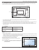
SV425 / SV465 / SV555 / SV427 / SV467 / SV557 1.5. Mounting on a Wall To mount this display to a wall, you will have to obtain a standard wall-mounting kit (commercially available). We recommend using a mounting interface that complies with TUV-GS and/or UL1678 standard in North America. Protective Sheet VESA Grid Table Tabletop stand 1. Lay a protective sheet on a table, which was wrapped around the display when it was packaged, beneath the screen surface so as not to scratch the screen face. 2.
SV425 / SV465 / SV555 / SV427 / SV467 / SV557 2. Parts and Functions 2.1. Control Panel 9 MUTE INPUT 1 1 2 3 MENU 4 5 6 7 8 functions. To enable or disable the keyboard control lock, press both [ ] and [ ] buttons and hold down continuously for more than 3 (three) seconds. POWER button Use this button to turn the display on or put the display to standby. 2 9 MUTE button • • Switch the audio mute ON/OFF.
SV425 / SV465 / SV555 / SV427 / SV467 / SV557 2.2. Input/Output Terminals 17 16 15 14 2 1 1 6 3 4 5 11 7 8 9 10 AC IN 10 MAIN POWER SWITCH 11 RS232C OUT 12 RS232C IN 13 RJ-45 14 HDMI IN 15 AC power input from the wall outlet. 2 DisplayPort 16 SPEAKERS OUT External speakers output. DVI IN DVI-D video input. 9 AUDIO OUT (RCA) Audio output from the AUDIO IN jack to an external AV device. DisplayPort video input. 8 AUDIO IN Audio input from external AV device (RCA).
SV425 / SV465 / SV555 / SV427 / SV467 / SV557 2.3. Remote Control 5 2.3.1. General functions 6 10 SMART AUDIO SOURCE 2 7 11 12 8 INPUT CHANGE 13 CONTRAST BRIGHTNESS 5 DISPLAY 6 10 EXIT VOL UP MUTE [MUTE] button [VIDEO SOURCE] button Press to toggle Video Source Menu. Press [ ] or [ ] button to select one of the video sources among Displayport, DVI-D, VGA, HDMI, Component, Video, or Card OPS. Press [SET] button to confirm and exit.
SV425 / SV465 / SV555 / SV427 / SV467 / SV557 2.3.2. Inserting the batteries in the remote control 2.3.4. Operating range of the remote control Point the top of the remote control toward the display’s remote control sensor when pressing a button. The remote control is powered by two 1.5V AAA batteries. Use the remote control within a distance of less than 10m/33ft from the display’s sensor, and a horizontal and vertical angle of less than 30 degrees. To install or replace batteries: 1.
SV425 / SV465 / SV555 / SV427 / SV467 / SV557 3. Connecting External Equipment 3.1. Using the Switch Cover A cover for the power switch is provided to prevent the display from being turned on or off accidentally. To lock the cover into position: 1. Align and insert the cover to the indentation located beside the power switch. 2. Use the screw to lock the cover.
SV425 / SV465 / SV555 / SV427 / SV467 / SV557 3.2. Connecting External Equipment (DVD/VCR/VCD) 3.2.1. Using COMPONENT video input Audio Out COMPONENT Out (YPbPr) [R] [L] DVD / VCR / VCD [AUDIO IN] [COMPONENT IN] (YPbPr) 3.2.2.
SV425 / SV465 / SV555 / SV427 / SV467 / SV557 3.3. Connecting a PC 3.3.1. Using VGA input VGA Out D-Sub 15 pin PC [R] Audio Out [L] [AUDIO IN] [VGA IN] [VGA AUDIO IN] 3.3.2. Using DVI input DVI Out PC [R] Audio Out [L] [AUDIO IN] [DVI IN] [VGA AUDIO IN] 3.3.3.
SV425 / SV465 / SV555 / SV427 / SV467 / SV557 3.4. Connecting Audio Equipment 3.4.1. Connecting external speakers External speakers 3.4.2.
SV425 / SV465 / SV555 / SV427 / SV467 / SV557 3.5. Connecting Multiple Displays in a Daisy-chain Configuration You can interconnect multiple displays to create a daisy-chain configuration for applications such as a video wall. NOTE: Maximum 25 displays (5x5) can be used in a daisy-chain configuration. 3.5.1. Display control connection Connect the [RS232C OUT] connector of DISPLAY 1 to the [RS232C IN] connector of DISPLAY 2.
SV425 / SV465 / SV555 / SV427 / SV467 / SV557 4. OSD Menu 4.2. An overall view of the On-Screen Display (OSD) structure is shown below. You can use it as a reference for further adjusting your display. 4.1. OSD Menu Overview 4.2.1. PICTURE menu PICTURE Navigating the OSD Menu 4.1.1.
SV425 / SV465 / SV555 / SV427 / SV467 / SV557 GAMMA SELECTION V POSITION Gamma is what controls the overall brightness of an image. Images which are not corrected properly can appear too white or too dark, so controlling the gamma properly can have a huge influence on the overall picture quality of your display. Press the [ ] button to move the image up, or [ ] to move the image down. CLOCK Adjust the width of the image. The options are: {NATIVE} / {2.2} / {2.4} / {S GAMMA}.
SV425 / SV465 / SV555 / SV427 / SV467 / SV557 4.2.4. PIP menu V ZOOM Expands the vertical size of the image only. PIP PIP MODE PIP SIZE PIP AUDIO PIP H POSITION PIP V POSITION SUB INPUT PIP RESET H POSITION Moves the horizontal position of the image left or right. PIP V POSITION Moves the vertical position of the image up or down. OFF SMALL MAIN AUDIO 100 0 VIDEO 1 2 3 INPUT RESOLUTION Set the resolution of the VGA input.
SV425 / SV465 / SV555 / SV427 / SV467 / SV557 PIP SBS ASPECT POP SBS FULL OFF SCHEDULE TODAY 1 2 3 4 5 6 7 The resolutions in the PIP and POP modes are configured as follows: PIP SIZE {SMALL} : 320 x 240 pixels {MIDDLE} : 480 x 320 pixels {LARGE} : 640 x 480 pixels POP SIZE : 474 x 355 pixels 2011 . 08 . 04 OFF _:_ ON _:_ EVERY DAY WED SAT +-:SEL NOTE: T he images displayed in the sub picture always fit the PIP sizes shown above irrespective of the aspect ratio of the input image.
SV425 / SV465 / SV555 / SV427 / SV467 / SV557 DATE AND TIME INFORMATION OSD Adjust the current date and time for the display’s internal clock. Set the period of time the information OSD displayed on the upper right corner of the screen. The information OSD will display when input signal is changed. DATE AND TIME YEAR MONTH DAY HOUR MINUTE DAYLIGHT SAVING TIME CURRENT DATE TIME 2011 . 08 . 04 :SEL +-:ADJ EXIT :RETURN The information OSD will remain on the screen with {OFF} selection.
SV425 / SV465 / SV555 / SV427 / SV467 / SV557 Example: 5 x 5 screen matrix (25 displays) H MONITORS = 5 displays V MONITORS = 5 displays not compliant with it, images may not be displayed correctly. CONFIGURATION2 RESET Reset all settings in the CONFIGURATION2 menu to factory preset values. V MONITORS H MONITORS 1 2 3 4 5 6 7 8 9 10 11 12 13 14 15 16 17 18 19 20 21 22 23 24 25 Position • H MONITORS - Select the number of displays on the horizontal side.
SV425 / SV465 / SV555 / SV427 / SV467 / SV557 SCREEN SAVER INPUT CHANGE Choose to enable the panel saving functions to reduce the risk of the “image persistence”. Select the time for input switching as {NORMAL} or {QUICK}. NOTE: The selection {QUICK} may cause a slight noise. SCREEN SAVER TERMINAL SETTING COOLING FAN BRIGHTNESS MOTION :SEL +-:ADJ Select the mode to display the HDMI or DVI signal according to their signal format depending on their source device.
SV425 / SV465 / SV555 / SV427 / SV467 / SV557 SERIAL CONTROL FACTORY RESET Select the network control port. The options are: {RS-232C} / {LAN}. NO NOTE: If {LAN} is selected, then {RS-232C} will not be activated, even if a cable is attached, and vice versa. YES LAN SETTING :SEL Assign {IP ADDRESS}, {SUBNET MASK}, and {DEFAULT GATEWAY} for the display.
SV425 / SV465 / SV555 / SV427 / SV467 / SV557 5. Input Mode VGA Resolution: Standard Resolution VGA WVGA SVGA XGA WXGA WXGA SXGA SXGA WXGA WXGA UXGA HD1080 Active Resolution H Pixels V Lines 480 640 480 480 720 400 600 800 600 768 1024 768 1280 768 1280 800 1280 960 1280 1024 1360 768 1366 768 1600 1200 1920 1080 Refresh Rate Pixel Rate Aspect Ratio Stand for Mode 60 Hz 72 Hz 75 Hz 70 Hz 60 Hz 75 Hz 60 Hz 75 Hz 60 Hz 60 Hz 60 Hz 60 Hz 60 Hz 60 Hz 60 Hz 60 Hz 25.175 MHz 31.5 MHz 31.5 MHz 33.
SV425 / SV465 / SV555 / SV427 / SV467 / SV557 6. Cleaning and Troubleshooting 6.1. Cleaning Caution When Using the Display • • • Do not bring your hands, face or objects close to the ventilation holes of the display. The top of the display is usually very hot due to the high temperature of exhaust air being released through the ventilation holes. Burns or personal injuries may occur if any body parts are brought too close.
SV425 / SV465 / SV555 / SV427 / SV467 / SV557 6.2. Troubleshooting Symptom Possible Cause Remedy No picture is displayed 1. The power cord is disconnected. 1. Plug in the power cord. 2. The main power switch on the back of the display is not switched on. 2. Make sure the power switch is switched on. 3. The selected input has no connection. 3. Connect a signal connection to the display. 4. The display is in standby mode.
SV425 / SV465 / SV555 / SV427 / SV467 / SV557 7. Technical Specifications 7.1. SV425 / SV427 Display: Item Specifications Screen Size (Active Area) 42” LCD Aspect Ratio 16:9 Number of pixels 1920 (H) x 1080 (V) Pixel pitch 0.4845 (H) x 0.
SV425 / SV465 / SV555 / SV427 / SV467 / SV557 Dimensions (Without Stand) [W x H x D] 965.8 x 558.8 x 69 mm Weight (With Stand) 20.3 Kg Weight (Without Stand) 18.3 Kg Gross Weight (Without Stand) 23.
SV425 / SV465 / SV555 / SV427 / SV467 / SV557 7.2. SV465 / SV467 Display: Item Specifications Screen Size (Active Area) 46” LCD Aspect Ratio 16:9 Number of pixels 1920 (H) x 1080 (V) Pixel pitch 0.17675 (H) x 0.53025 (V) [mm] Displayable colors 1073.
SV425 / SV465 / SV555 / SV427 / SV467 / SV557 Weight (Without Stand) 22.0 Kg Gross Weight (Without Stand) 27.
SV425 / SV465 / SV555 / SV427 / SV467 / SV557 7.3. SV555 / SV557 Display: Item Specifications Screen Size (Active Area) 55” LCD Aspect Ratio 16:9 Number of pixels 1920 (H) x 1080 (V) Pixel pitch 0.21 (H) x 0.63 (V) [mm] Displayable colors 1073.
SV425 / SV465 / SV555 / SV427 / SV467 / SV557 Weight (Without Stand) 30.6 Kg Gross Weight (Without Stand) 36.
© 2013 All rights reserved. Specifications are subject to change without notice.