
Specifications


4-6 Chapter 4: Motherboard Info
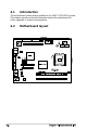
2. ATX power connectors (24-pin EATXPWR, 4-pin ATX12V)
These connectors are for the 24-pin and 4-pin power plugs from the
power supply unit. The plugs from the power supply unit are designed
to t these connectors in only one orientation. Find the proper
orientation and push down rmly until the connectors completely t.
Do not forget to connect the 4-pin ATX12V power plug to the ATX12V
connector on the motherboard; otherwise, the system will not boot up.
R
P5L13L
P5L13L A
TX Power Connector
EATXPWR
+3 Volts
+3 Volts
Ground
+5 Volts
+5 Volts
Ground
Ground
Power OK
+5V Standby
+12 Volts
-5 Volts
+5 Volts
+3 Volts
-12 Volts
Ground
Ground
Ground
PSON#
Ground
+5 Volts
+12 Volts
+3 Volts
+5 Volts
Ground
ATX12V
GND
+12V DC
GND
+12V DC
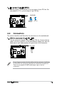
3. IDE connector (40-1 pin PRI_IDE)
This connector is for an IDE 100/66 signal cable, a blue connector for
the primary IDE connector on the motherboard
• Pin 20 on the IDE connector is removed to match the covered hole
on the Ultra DMA cable connector. This prevents incorrect insertion
when you connect the IDE cable.
• Use the 80-conductor IDE cable for Ultra DMA 100/66 IDE devices.
R
P5L13L
P5L13L
IDE Connector
NOTE: Orient the red markings
(usually zigzag) on the ID
ribbon cable to PIN 1.
PRI_IDE
PIN1