
User Manual
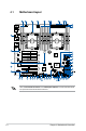
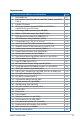
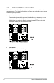
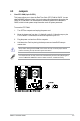
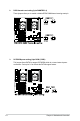
Table Of Contents
- Safety information
- Chapter 1: Product Introduction
- Chapter 2: Hardware Information
- Chapter 3: Installation Options
- Chapter 4: Motherboard Information
- Chapter 5: BIOS Setup
- 5.1 Managing and updating your BIOS
- 5.2 BIOS setup program
- 5.3 Main menu
- 5.4 Ai Tweaker menu
- 5.5 Performance Tuning menu
- 5.6 Advanced menu
- 5.6.1 Trusted Computing
- 5.6.2 ACPI Settings
- 5.6.3 SMART Self Test
- 5.6.4 Super IO Configuration
- 5.6.5 Serial Port Console Redirection
- 5.6.6 Onboard LAN Configuration
- 5.6.7 APM
- 5.6.8 PCI Subsystem Settings
- 5.6.9 Network Stack Configuration
- 5.6.10 CSM Configuration
- 5.6.11 NVMe Configuration
- 5.6.12 USB Configuration
- 5.6.13 iSCSI Configuration
- 5.6.14 Intel(R) Virtual RAID on CPU
- 5.7 Platform Configuration menu
- 5.8 Socket Configuration menu
- 5.9 Event Logs menu
- 5.10 Server Mgmt menu
- 5.11 Monitor menu
- 5.12 Security menu
- 5.13 Boot menu
- 5.14 Tool menu
- 5.15 Save & Exit menu
- Chapter 6: RAID Configuration
- Chapter 7: Driver Installation
- Appendix

ASUS TS700-E9 Series
4-3
Layout contents
Connectors/Jumpers/Buttons and switches/Slots Page
1. DDR4 DIMM slots 2-7
2. Fan connectors (4-pin CPU_FAN1-2; 4-pin FRNT_FAN1-5; 4-pin REAR_
FAN1-2)
4-20
3. LGA3647 CPU socket 2-4
4. ATX power connectors (24-pin EATXPWR; 8-pin EATX12V1;
8-pin EATX12V2; 6-pin EATX12V3)
4-23
5. Power Supply SMBus connector (5-pin PSUSMB) 4-24
6. PMBus 1.2 PSU select jumper (3-pin SMART_PSU1) 4-7
7. DDR4 thermal event setting (3-pin DIMMTRIP1-2) 4-6
8. SATADOM power setting (3-pin DOM1_PWR1) 4-6
9. U.2 connectors (U.2_1; U.2_2; U.2_3; U.2_4) 4-16
10. Intel
®
C621 Serial ATA 6 Gb/s connectors (7-pin SATA1-8) 4-13
11. ASMedia
®
Serial ATA 6 Gb/s connectors (7-pin SATA_E1-2) 4-13
12. Auxiliary panel connector (20-2 pin AUX_PANEL1) 4-22
13. Chassis Intrusion connector (2-pin INTRUSION1) 4-15
14. System panel connector (20-1 pin PANEL1) 4-21
15. Serial General Purpose Input/Output connector (6-1 pin SGPIO1) 4-26
16. TPM connector (14-1 pin TPM1) 4-15
17. Clear RTC RAM (3-pin CLRTC1) 4-5
18. ME firmware force recovery setting (3-pin ME_RCVR1) 4-7
19. System Management Bus (SMBUS) connector (5-1 pin SMBUS1) 4-25
20. VROC_KEY connector (4-pin VROC_KEY1) 4-17
21. USB 3.1 Gen 1 connectors (20-1 pin USB3_E12; 20-1 pin USB3_E34) 4-19
22. PCH_MFG1 Setting (3-pin PCH_MFG1) 4-8
23. M.2 (NGFF) connectors (NGFF1) 4-17
24. VGA controller setting (3-pin VGA_SW1) 4-9
25. USB 2.0 connector (10-1 pin USB78) 4-18
26. IPMI SW setting (3-pin IPMI_SW1) 4-8
27. VPP_I2C1 connector (10-1 pin VPP_I2C1) 4-25
28. Q-Code LEDs 4-12
29. Reset button 4-4
30. Power-on button 4-4
31. Serial port connector (10-1 pin COM1) 4-24
32. VGA connector (16-1 pin VGA_HDR1) 4-16
33. Front panel audio connector (10-1 pin AAFP) 4-14
34. Hard disk activity LED connector (4-pin HDLED1) 4-14
35. BMC connector (14-1 pin ASMB9) 4-26
36. Micro SD card slot (MSD1) 4-27