Motherboard TUF B365M-PLUS GAMING
E15431 First Edition April 2019 Copyright © 2019 ASUSTeK COMPUTER INC. All Rights Reserved. No part of this manual, including the products and software described in it, may be reproduced, transmitted, transcribed, stored in a retrieval system, or translated into any language in any form or by any means, except documentation kept by the purchaser for backup purposes, without the express written permission of ASUSTeK COMPUTER INC. (“ASUS”).
Contents Safety information....................................................................................... iv About this guide.......................................................................................... iv Package contents........................................................................................ vi TUF B365M-PLUS GAMING specifications summary............................... vi Chapter 1: Product introduction Motherboard overview..........................................
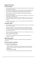
Safety information Electrical safety • To prevent electrical shock hazard, disconnect the power cable from the electrical outlet before relocating the system. • When adding or removing devices to or from the system, ensure that the power cables for the devices are unplugged before the signal cables are connected. If possible, disconnect all power cables from the existing system before you add a device.
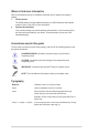
Where to find more information Refer to the following sources for additional information and for product and software updates. 1. ASUS websites The ASUS website provides updated information on ASUS hardware and software products. Refer to the ASUS contact information. 2. Optional documentation Your product package may include optional documentation, such as warranty flyers, that may have been added by your dealer. These documents are not part of the standard package.
Package contents Check your motherboard package for the following items. Motherboard ASUS TUF B365M-PLUS GAMING motherboard Cables 2 x Serial ATA 6.0 Gb/s cables Accessories 1 x I/O Shield 1 x M.2 Screw package 1 x TUF GAMING sticker Application DVD Support DVD Documentation User Guide TUF Certification Card If any of the above items is damaged or missing, contact your retailer.
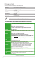
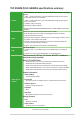
TUF B365M-PLUS GAMING specifications summary Intel® B365 Chipset with RAID 0, 1, 5, 10 and Intel® Rapid Storage Technology support - 1 x M.2_1 Socket 3 with M Key, type 2242/2260/2280 storage devices support (both SATA and PCIe 3.0 x 4 modes)* Storage - 1 x M.2_2 Socket 3 with M Key, type 2242/2260/2280 storage devices support (PCIe 3.0 x 4 mode) - 6 x SATA 6.0 Gb/s ports (gray) - Intel® Optane™ Memory Ready * When a device in SATA mode is installed on the M.2_1 socket, SATA6G_1 port cannot be used.
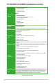
TUF B365M-PLUS GAMING specifications summary ASUS Exclusive Features - ASUS Ai Charger - ASUS AI Suite 3 - ASUS PC Cleaner EZ DIY ASUS special features UEFI BIOS EZ Mode - Featuring friendly graphics user interface - ASUS CrashFree BIOS 3 - ASUS EZ Flash 3 Q-Design - ASUS Q-DIMM - ASUS Q-Slot ASUS Quiet Thermal Quiet Thermal Design Solution - Stylish Fanless Design: PCH Heat-sink, MOS Heat-sink, and M.
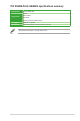
TUF B365M-PLUS GAMING specifications summary Manageability WOL by PME, PXE Drivers Support DVD ASUS utilities EZ Update Anti-virus software (OEM version) OS Support Windows® 10 (64-bit) Form Factor mATX Form Factor, 9.6”x 9.5” (24.4cm x 24.1cm) Specifications are subject to change without notice.
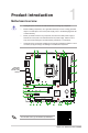
1 Product introduction Motherboard overview • Unplug the power cord from the wall socket before touching any component. • Before handling components, use a grounded wrist strap or touch a safely grounded object or a metal object, such as the power supply case, to avoid damaging them due to static electricity. • Before you install or remove any component, ensure that the ATX power supply is switched off or the power cord is detached from the power supply.
CPU and chassis fan connectors (4-pin CPU_FAN, 4-pin CHA_FAN1~2) Connect the fan cables to the fan connectors on the motherboard, ensuring that the black wire of each cable matches the ground pin of the connector. Do not forget to connect the fan cables to the fan connectors. Insufficient air flow inside the system may damage the motherboard components. These are not jumpers! Do not place jumper caps on the fan connectors! The CPU_FAN connector supports a CPU fan of maximum 1A (12 W) fan power.
Addressable RGB header (4-1 pin ADD_HEADER) This connector is for individually addressable RGB WS2812B LED strips or WS2812B based LED strips. The addressable RGB header supports WS2812B addressable RGB LED strips (5V/Data/ Ground), with a maximum power rating of 3A (5V) and a maximum of 120 LEDs. Before you install or remove any component, ensure that the ATX power supply is switched off or the power cord is detached from the power supply.
Clear RTC RAM (2-pin CLRTC) CLRTC +3V_BAT GND This header allows you to clear the CMOS RTC RAM data of the system setup information such as date, time, and system passwords. To erase the RTC RAM: PIN 1 1. Turn OFF the computer and unplug the power cord. 2. Use a metal object such as a screwdriver to short the two pins. 3. Plug the power cord and turn ON the computer. 4. Hold down the key during the boot process and enter BIOS setup to re-enter data.
Front panel audio connector (10-1 pin AAFP) This connector is for a chassis-mounted front panel audio I/O module that supports either HD Audio or legacy AC`97 audio standard. Connect one end of the front panel audio I/O module cable to this connector. • We recommend that you connect a high-definition front panel audio module to this connector to avail of the motherboard’s high-definition audio capability.
Rear panel connectors 1 2 4 3 9 10 5 6 8 7 1. PS/2 mouse/keyboard combo port. This port connects to a PS/2 mouse or PS/2 keyboard. 2. DVI-D port. This port is for any DVI-D compatible device. DVI-D can not be converted to output from RGB Signal to CRT and is not compatible with DVI-I. 3. DisplayPort. This port is for DisplayPort-compatible devices. 4. LAN (RJ-45) port. This port allows Gigabit connection to a Local Area Network (LAN) through a network hub.
Audio 2.1, 4.1, 5.1, or 7.1-channel configuration Port Light Blue (Rear panel) Lime (Rear panel) Pink (Rear panel) Lime (Front panel) Headset 2.1-channel Line In Line Out Mic In - 4.1-channel Rear Speaker Out Front Speaker Out Mic In - 5.1-channel Rear Speaker Out Front Speaker Out Bass/Center - 7.1-channel Rear Speaker Out Front Speaker Out Bass/Center Side Speaker Out To configure a 7.1-channel audio output: Use a chassis with HD audio module in the front panel to support a 7.1-channel audio output.
Central Processing Unit (CPU) This motherboard comes with a surface mount LGA1151 socket designed for the 9th / 8th Generation Intel® Core™, Pentium® Gold and Celeron® processors. Unplug all power cables before installing the CPU. • Ensure that you install the correct CPU designed for the LGA1151 socket only. DO NOT install a CPU designed for LGA1150, LGA1155 and LGA1156 sockets on the LGA1151 socket.
System memory Overview This motherboard comes with four Double Data Rate 4 (DDR4) Dual Inline Memory Module (DIMM) sockets. A DDR4 module is notched differently from a DDR, DDR2, or DDR3 module. DO NOT install a DDR, DDR2, or DDR3 memory module to the DDR4 slot. DIMM_B1 DIMM_B2* DIMM_A1 DIMM_A2* Channel Sockets Channel A DIMM_A1 and DIMM_A2* Channel B DIMM_B1 and DIMM_B2* • You may install varying memory sizes in Channel A and Channel B.
Installing a DIMM 1 2 A A B To remove a DIMM A B Chapter 1: Product introduction 1-10
2 BIOS information • Scan the QR code to view the BIOS update guide. • Before using the ASUS CrashFree BIOS 3 utility, rename the BIOS file in the removable device into TB365MP.CAP. BIOS setup program Use the BIOS Setup program to update the BIOS or configure its parameters. The BIOS screens include navigation keys and brief online help to guide you in using the BIOS Setup program.
EZ Mode By default, the EZ Mode screen appears when you enter the BIOS setup program. The EZ Mode provides you an overview of the basic system information, and allows you to select the display language, system performance mode, fan profile and boot device priority. To access the Advanced Mode, click Advanced Mode(F7) or press . The default screen for entering the BIOS setup program can be changed. Refer to the Setup Mode item under the Boot menu for details.
Advanced Mode The Advanced Mode provides advanced options for experienced end-users to configure the BIOS settings. The figure below shows an example of the Advanced Mode. Refer to the following sections for the detailed configurations. To access the EZ Mode, click EzMode(F7) or press .
Search on FAQ Move your mouse over this button to show a QR code. Scan this QR code with your mobile device to connect to the ASUS BIOS FAQ web page. You can also scan the QR code below. Exit menu The Exit menu items allow you to load the optimal default values for the BIOS items, and save or discard your changes to the BIOS items. Load Optimized Defaults This option allows you to load the default values for each of the parameters on the Setup menus.
Appendix Notices FCC Compliance Information Responsible Party: Address: Phone / Fax No: Asus Computer International 48720 Kato Rd., Fremont, CA 94538, USA (510)739-3777 / (510)608-4555 This device complies with part 15 of the FCC Rules. Operation is subject to the following two conditions: (1) This device may not cause harmful interference, and (2) this device must accept any interference received, including interference that may cause undesired operation.
Compliance Statement of Innovation, Science and Economic Development Canada (ISED) This device complies with Innovation, Science and Economic Development Canada licence exempt RSS standard(s). Operation is subject to the following two conditions: (1) this device may not cause interference, and (2) this device must accept any interference, including interference that may cause undesired operation of the device.
REACH Complying with the REACH (Registration, Evaluation, Authorisation, and Restriction of Chemicals) regulatory framework, we published the chemical substances in our products at ASUS REACH website at http://csr.asus.com/english/REACH.htm. DO NOT throw the motherboard in municipal waste. This product has been designed to enable proper reuse of parts and recycling.
English ASUSTeK Computer Inc. hereby declares that this device is in compliance with the essential requirements and other relevant provisions of related Directives. Full text of EU declaration of conformity is available at: www.asus.com/support Français AsusTek Computer Inc. déclare par la présente que cet appareil est conforme aux critères essentiels et autres clauses pertinentes des directives concernées. La déclaration de conformité de l’UE peut être téléchargée à partir du site Internet suivant : www.
ASUS contact information ASUSTeK COMPUTER INC. Address Telephone Fax Web site Technical Support Telephone Fax Online support 4F, No. 150, Li-Te Road, Peitou, Taipei 112, Taiwan +886-2-2894-3447 +886-2-2890-7798 www.asus.com +86-21-38429911 +86-21-5866-8722, ext. 9101# http://qr.asus.com/techserv ASUS COMPUTER INTERNATIONAL (America) Address 48720 Kato Rd., Fremont, CA 94538, USA Telephone +1-510-739-3777 Fax +1-510-608-4555 Web site http://www.asus.