
User's Manual

1-4
Chapter 1: Product introduction
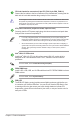
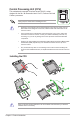
Clear RTC RAM (2-pin CLRTC)
ThisheaderallowsyoutocleartheCMOSRTCRAMdataof
thesystemsetupinformationsuchasdate,time,andsystem
passwords.
To erase the RTC RAM:
1. TurnOFFthecomputerandunplugthepowercord.
2. Useametalobjectsuchasascrewdrivertoshortthetwo
pins.
3. PlugthepowercordandturnONthecomputer.
4. Holddownthe<Del>keyduringthebootprocessandenter
BIOSsetuptore-enterdata.
CLRTC
+3V_BAT
GND
PIN 1
Ifthestepsabovedonothelp,removetheonboardbatteryandshortthetwopinsagain
tocleartheCMOSRTCRAMdata.AfterclearingtheCMOS,reinstallthebattery.
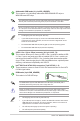
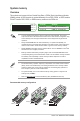
Digital audio connector (4-1 pin SPDIF_OUT)
ConnecttheS/PDIFOutmodulecabletothisconnector,then
installthemoduletoaslotopeningatthebackofthesystem
chassis.
SPDIF_OUT
+5V
SPDIFOUT
GND
PIN 1
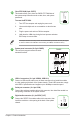
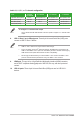
System panel connector (20-5 pin PANEL)
Thisconnectorsupportsseveralchassis-
mountedfunctions.
* Requires an ATX power supply
PLED+
PLED-
PWRBTN#
GND
+5V
GND
GND
Speaker
HDD_LED+
HDD_LED-
GND
RSTCON#
NC
PLED+
PLED-
PIN 1
+PWR_LED-
+PWR_LED-
SPEAKER
PANEL
+HDD_LED-
PWR_SW
RESET
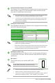
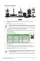
USB 2.0 connectors (10-1 pin USB910, USB1112)
ConnectaUSBmodulecabletoanyoftheseconnectors,theninstallthemodule
toaslotopeningatthebackofthesystemchassis.TheseUSBconnectorscomply
withUSB2.0specicationsandsupportsupto480Mbpsconnectionspeed.
Serial port connector (10-1 pin COM)
Connecttheserialportmodulecabletothisconnector,theninstallthemoduletoa
slotopeningatthebackofthesystemchassis.