Carte mère TUF GAMING B650-PLUS WIFI
F21902 Troisième Édition Avril 2023 Copyright © 2023 ASUSTeK COMPUTER INC. Tous droits réservés. Aucun extrait de ce manuel, incluant les produits et logiciels qui y sont décrits, ne peut être reproduit, transmis, transcrit, stocké dans un système de restitution, ou traduit dans quelque langue que ce soit sous quelque forme ou quelque moyen que ce soit, à l'exception de la documentation conservée par l'acheteur dans un but de sauvegarde, sans la permission écrite expresse de ASUSTeK COMPUTER INC. (“ASUS”).
Table des matières Consignes de sécurité................................................................................................................iv À propos de ce manuel...............................................................................................................v Contenu de la boîte....................................................................................................................vi Résumé des caractéristiques de la TUF GAMING B650-PLUS WIFI..........................
Consignes de sécurité Sécurité électrique • Pour éviter tout risque de choc électrique, débranchez le câble d'alimentation de la prise électrique avant de toucher au système. • Lors de l'ajout ou du retrait de composants, vérifiez que les câbles d'alimentation sont débranchés avant de brancher d'autres câbles. Si possible, déconnectez tous les câbles d'alimentation du système avant d'y installer un périphérique.
À propos de ce manuel Ce manuel de l'utilisateur contient les informations dont vous aurez besoin pour installer et configurer la carte mère. Organisation du manuel Ce manuel contient les parties suivantes : • Chapitre 1 : Introduction au produit Ce chapitre décrit les fonctions de la carte mère et les technologies prises en charge. Il inclut également une description des cavaliers et des divers connecteurs, boutons et interrupteurs de la carte mère.
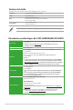
Contenu de la boîte Vérifiez la présence des éléments suivants dans l'emballage de votre carte mère. Carte mère 1 x Carte mère TUF GAMING B650-PLUS WIFI Câbles 2 x Câbles SATA 6 Gb/s Divers 1 x Antennes WiFi amovibles ASUS 2 x Kits de protections en caoutchouc pour module M.2 1 x Kit de vis pour SSD M.2 Documentation 1 x Carte de certification TUF 1 x Manuel de l'utilisateur Si l'un des éléments ci-dessus est endommagé ou manquant, veuillez contacter votre revendeur.
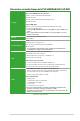
Résumé des caractéristiques de la TUF GAMING B650-PLUS WIFI Stockage 3 x Slots M.2 et 4 x Ports SATA 6 Gb/s* Processeurs AMD® Ryzen™ de la série 7000 Slot M.2_1 pour lecteurs M Key 2242/2260/2280 (Mode PCIe 5.0 x4) Slot M.2_2 pour lecteurs M Key 2242/2260/2280/22110 (Mode PCIe 4.0 x4) Chipset AMD® B650 Slot M.2_3 pour lecteurs M Key 2242/2260/2280 (Mode PCIe 4.0 x4)** 4 x Connecteurs SATA 6.0 Gb/s * Technologie AMD® RAIDXpert2 avec prise en charge RAID 0/1/10 (PCIe) et RAID 0/1/10 (SATA). ** M.
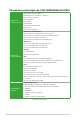
Résumé des caractéristiques de la TUF GAMING B650-PLUS WIFI Interfaces de connexion arrières 1 x Port USB 3.2 Gen 2x2 (1 x Type-C®) 3 x Ports USB 3.2 Gen 2 (2 x Type-A + 1 x Type-C®) 4 x Ports USB 2.0 (2 x Type-A) 1 x Port DisplayPort 1 x Port HDMI 1 x Module WiFi 1 x Port Ethernet Realtek 2.
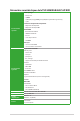
Résumé des caractéristiques de la TUF GAMING B650-PLUS WIFI Fonctionnalités spéciales ASUS Q-Design - M.2 Q-Latch - Q-DIMM - Q-LED (CPU [rouge], DRAM [jaune], VGA [blanc], Boot Device [jaune vert]) - Q-Slot Solution de dissipation thermique ASUS - Dissipateur thermique M.
x • Les caractéristiques sont sujettes à modifications sans préavis. Visitez le site internet d'ASUS pour consulter la dernière liste des caractéristiques de cette carte mère. • MyASUS offre une variété de fonctions de support telles que le dépannage, l'optimisation de la performance des produits, l'intégration des logiciels ASUS et la création d'un lecteur de récupération. Scannez le code pour consulter le guide d'installation et la FAQ.
Introduction au produit 1.1 Avant de commencer 1 Suivez les précautions ci-dessous avant d'installer la carte mère ou d'en modifier les paramètres. • Débranchez le câble d'alimentation de la prise murale avant de toucher les composants. • Utilisez un bracelet antistatique ou touchez un objet métallique relié au sol (comme l'alimentation) pour vous décharger de toute électricité statique avant de toucher aux composants.
1.2 Vue d'ensemble de la carte mère 5 24.4cm(9.6in) 1 2 4 11 ADD_GEN 2_1 CPU_FAN DIGI +VRM CPU_OPT CPU DRAM VGA BOOT 19 ATX_PWR ADD_GEN 2_2 AIO_PUMP ATX_12V_2 ATX_12V_1 HDMI_DP 5 U32G2_C2 Placez ce côté vers l'arrière du châssis M.2(WIFI) FLBK_LED U32G1_89 18 30.
1.2.1 Contenu du schéma 1. Socket du processeur La carte mère est équipée d'un socket AM5 conçu pour les processeurs d'ordinateurs de bureau AMD® Ryzen™ de la série 7000. Pour plus de détails, consultez la section Processeur. 2. Slots DIMM DDR5 La carte mère est équipée de slots DIMM réservés à l'installation de modules de mémoire DDR5. Pour plus de détails, consultez la section Mémoire système. 3.
6. Slots M.2 (M Key) Les slots M.2 vous permettent d'installer des périphériques M.2, tels que des SSD M.2. • Processeurs AMD® Ryzen™ de la série 7000 : - Le slot M.2_1 prend en charge les modules PCIe 5.0 x4 (pour lecteurs M Key 2242/2260/2280). - Le slot M.2_2 prend en charge les modules PCIe 4.0 x4 (pour lecteurs M Key 2242/2260/2280/22110). • Chipset AMD® B650 : - Le slot M.2_3 prend en charge les modules PCIe 4.0 x4 (pour lecteurs M Key 2242/2260/2280). 7.
Avant d'installer ou de désinstaller un composant, assurez-vous que l'alimentation est éteinte et que le câble d'alimentation est bien débranché. Le non-respect de cette précaution peut endommager la carte mère, les périphériques et/ou les composants. • L'éclairage et les couleurs réels varient en fonction de la bande LED. • Si votre bande LED ne s'allume pas, vérifiez que la bande LED RGB adressable est connectée dans le bon sens, et que le connecteur 5V est aligné avec l'en-tête 5V de la carte mère.
14. Connecteur pour port série (COM) Le connecteur de port série (COM) vous permet de connecter un module de port série. Connectez le câble du module de port série à ce connecteur, puis installez le module sur un slot libre à l'arrière du châssis. AAFP PORT1 L PORT1 R PORT2 R SENSE_SEND PORT2 L Il est recommandé de brancher un module HD Audio sur ce connecteur pour bénéficier d'un son de qualité HD. AGND NC SENSE1_RETUR 15.
La carte et les câbles Thunderbolt™ sont vendus séparément. • Visitez le site officiel du fabricant de votre carte Thunderbolt™ pour plus de détails sur la compatibilité. TB_HEADER L a carte Thunderbolt™ ne peut être utilisée que lorsqu'elle est installée sur le slot PCIEX16_2. Assurez-vous d'installer la carte Thunderbolt™ sur le slot PCIEX16_2. FORCE_PWR CIO_PLUG_EVENT SLP_S3# SLP_S5# GND PIN 1 RTD3_SW • I2C_SCL I2C_SDA I2C_IRQ# RTD3_POWER_EN S_SLP_S0#_IDLE PERST_N WAKE# 17.
1.2.2 Connecteurs arrières 1 2 8 9 3 4 2 5 10 11 6 7 12 13 14 1. DisplayPort. Ce port est destiné aux appareils compatibles DisplayPort. 2. Ports USB 3.2 Gen 2 10 Gb/s (bleu-vert, Type-A). Ces ports USB 3.2 permettent de connecter des périphériques USB 3.2 Gen 2. 3. Ports USB 2.0. Ces ports USB permettent de connecter des périphériques USB 2.0. 4. Port Ethernet 2.5Gb. Ce port permet une connexion Ethernet 2.5G à un réseau local (LAN) via un hub réseau.
10. Port USB 3.2 Gen 2x2 (jusqu'à 20 Gb/s) (USB Type-C®). Ce port USB 3.2 permet de connecter un périphérique USB 3.2 Gen 2x2 Type-C®. 11. Ports WiFi 6. Ces ports permettent de connecter les antennes WiFi. Consultez la section 1.6 Installer l'antenne WiFi amovible pour plus de détails. 12. Bouton BIOS Flashback™. Maintenez le bouton BIOS Flashback™ enfoncé pendant 3 secondes jusqu'à ce que la LED clignote à trois reprises, puis relâchez. La fonction BIOS Flashback™ est alors activée.
1.3 Processeur La carte mère est équipée d'un socket AM5 conçu pour les processeurs d'ordinateurs de bureau AMD® Ryzen™ de la série 7000. Assurez-vous que tous les câbles sont débranchés lors de l'installation du processeur. • Le socket AM5 possède des broches différentes. Assurez-vous de n'installer qu'un processeur conçu pour le socket AM5. Le processeur ne peut être installé que dans un seul sens.
TUF GAMING B650-PLUS WIFI 1-11
1.4 Mémoire système La carte mère est équipée de slots DIMM réservés à l'installation de modules de mémoire DDR5. L'illustration ci-dessous indique l'emplacement des slots DIMM DDR5 : DIMM_A1 DIMM_A2 DIMM_B1 DIMM_B2 Canal Sockets Canal A DIMM_A1 & DIMM_A2 Canal B DIMM_B1 & DIMM_B2 Un module mémoire DDR5 s'encoche différemment d'un module DDR4 / DDR3 / DDR2 / DDR. NE PAS installer de module de mémoire DDR4, DDR3, DDR2 ou DDR sur les slots DIMM destinés aux modules DDR5.
Installer un module de mémoire 1 2 A A B Retirer un module de mémoire A B TUF GAMING B650-PLUS WIFI 1-13
1.5 Installer une carte M.2 • Utilisez un tournevis Phillips pour installer ou retirer les vis ou supports à vis mentionnés dans cette section. • La carte M.2 est vendue séparément. 1. Dévissez complètement les vis du/des dissipateur(s) thermique(s). 2. Retirez le(s) dissipateur(s) thermique(s). 1 2 1 1 2 1 3. Installez votre module M.2 dans le slot M.2. Pour les longueurs 2280 et 22110 A. (optionnel) Retirez le loquet amovible M.
Pour les longueurs 2242 et 2260 A. Installez le support à vis fourni dans le trou de vis situé à la longueur adaptée à votre lecteur M.2. B. Installez votre module M.2 dans le slot M.2. C. Fixez votre module M.2 en utilisant la vis du support à vis. 4. • Cette protection en caoutchouc M.2 est optionnelle lorsque vous installez un périphérique de stockage M.2 simple face. Assurez-vous d'installer la protection en caoutchouc M.2 avant d'installer votre périphérique de stockage M.2 simple face.
6 4 6 6 5 5 4 1.6 6 Installer l'antenne WiFi amovible Installer l'antenne WiFi amovible ASUS Connectez l'antenne WiFi amovible ASUS incluse sur les ports dédiés situés à l'arrière du châssis de votre ordinateur. • Assurez-vous que l'antenne WiFi amovible ASUS est bien installée sur les ports WiFi. • Placez l'antenne à plus de 20 cm de toute personne. L'illustration ci-dessus est donnée à titre indicatif uniquement.
TUF GAMING B650-PLUS WIFI 1-17
BIOS et configurations RAID 2 Pour plus d'informations sur le BIOS et les configurations RAID, consultez la page : www.asus.com/fr/support. 2.1 Présentation du BIOS Le tout nouveau BIOS UEFI (Extensible Firmware Interface) d'ASUS est conforme à l'architecture UEFI et offre une interface conviviale allant au-delà de la simple saisie traditionnelle au clavier grâce à la possibilité de configuration du BIOS à la souris.
2.2 Programme de configuration du BIOS Utilisez le programme de configuration du BIOS pour mettre à jour ou modifier les options de configuration du BIOS. L'écran du BIOS comprend les touches de navigation et une aide rapide pour vous guider lors de l'utilisation du programme de configuration du BIOS. Accéder au BIOS au démarrage du système Pour accéder au BIOS au démarrage du système, appuyez sur ou lors du POST (PowerOn Self Test). Si vous n'appuyez pas sur
2.3 ASUS EZ Flash 3 ASUS EZ Flash 3 vous permet de mettre à jour le BIOS sans avoir à passer par un utilitaire Windows®. Assurez-vous de charger les paramètres par défaut du BIOS pour garantir la stabilité et la compatibilité du système. Choisissez l'option Load Optimized Settings (Charger les valeurs optimisées par défaut) du menu Exit ou appuyez sur la touche .
2.4 ASUS CrashFree BIOS 3 ASUS CrashFree BIOS 3 est un outil de récupération automatique qui permet de restaurer le BIOS lorsqu'il est défectueux ou corrompu suite à une mise à jour. Vous pouvez mettre à jour un BIOS corrompu en utilisant un périphérique de stockage USB contenant le fichier BIOS à jour. Restaurer le BIOS 1. Téléchargez la dernière version du BIOS de votre carte mère en vous rendant sur https://www.asus.com/fr/support/. 2. Renommez le fichier du BIOS ASUS.CAP ou TGB650PW.
2.5 Configuration de volumes RAID Cette carte mère est livrée avec l'utilitaire de configuration RaidXpert2 qui prend en charge les configurations suivantes : Volume, RAIDABLE, RAID 0, RAID 1 et RAID 10 (en fonction de la licence du système). Pour plus d'informations sur la configuration des volumes RAID, veuillez consulter le Guide de configuration RAID disponible sur https://www.asus.com/fr/support, ou scanner ce code.
2-6 Chapitre 2 : BIOS et configurations RAID
Annexes Notices Informations de conformité FCC Partie responsable : Asus Computer International Adresse : 48720 Kato Rd., Fremont, CA 94538, USA Numéro de fax / (510)739-3777 / (510)608-4555 téléphone : Cet appareil est conforme à l'alinéa 15 des règles établies par la FCC.
Compliance Statement of Innovation, Science and Economic Development Canada (ISED) This device complies with Innovation, Science and Economic Development Canada licence exempt RSS standard(s). Operation is subject to the following two conditions: (1) this device may not cause interference, and (2) this device must accept any interference, including interference that may cause undesired operation of the device.
Précautions d'emploi de l'appareil : a. Soyez particulièrement vigilant quant à votre sécurité lors de l’utilisation de cet appareil dans certains lieux (les avions, les aéroports, les hôpitaux, les stations-service et les garages professionnels). b. Évitez d’utiliser cet appareil à proximité de dispositifs médicaux implantés.
Déclaration de conformité aux normes environnementales ASUS développe une conception écologique pour tous ses produits et s'assure que des standards élevés en terme de protection de l'environnement sont respectés tout au long du processus de fabrication. De plus, ASUS met à votre disposition des informations sur les différentes normes de respect de l'environnement. Consultez le site http://csr.asus.com/Compliance.
Déclaration simplifiée de conformité de l’UE ASUSTek Computer Inc. déclare par la présente que cet appareil est conforme aux critères essentiels et autres clauses pertinentes de la directive 2014/53/ EU. La déclaration de conformité de l’UE peut être téléchargée à partir du site internet suivant : https://www.asus.
Garantie Garantie ASUS • ASUS fournit une garantie commerciale en tant que garantie volontaire du fabricant. • ASUS se réserve le droit d'interpréter et de clarifier les informations relatives à la garantie commerciale ASUS. • Cette garantie commerciale ASUS est fournie indépendamment et parallèlement à la garantie légale, elle n'affecte ou ne limite d'aucune façon les droits acquis par la garantie légale. Pour plus d'informations sur la garantie, consultez le site https://www.asus.com/fr/support/.
Informations de contact ASUS ASUSTeK COMPUTER INC. Adresse : 1F, No. 15, Lide Rd., Beitou Dist., Taipei City 112 ASUS COMPUTER INTERNATIONAL (Amérique) Adresse : 48720 Kato Rd.