Motherboard TUF Z370-PRO GAMING
E13395 First Edition August 2017 Copyright© 2017 ASUSTeK COMPUTER INC. All Rights Reserved. No part of this manual, including the products and software described in it, may be reproduced, transmitted, transcribed, stored in a retrieval system, or translated into any language in any form or by any means, except documentation kept by the purchaser for backup purposes, without the express written permission of ASUSTeK COMPUTER INC. (“ASUS”).
Contents Safety information....................................................................................................... vi About this guide......................................................................................................... vii TUF Z370-PRO GAMING specifications summary................................................... ix Package contents...................................................................................................... xiv Chapter 1: 1.1 1.1.
Chapter 3: 3.1 3.2 BIOS setup program................................................................................... 3-2 3.2.1 EZ Mode...................................................................................... 3-3 3.2.2 Advanced Mode........................................................................... 3-4 3.2.3 QFan Control............................................................................... 3-7 3.2.4 EZ Tuning Wizard....................................................
Chapter 4: 4.1 4.2 RAID Support RAID configurations................................................................................... 4-1 4.1.1 RAID definitions........................................................................... 4-1 4.1.2 Installing storage devices............................................................. 4-2 4.1.3 Intel® Rapid Storage Technology in UEFI BIOS........................... 4-2 4.1.4 Intel® Rapid Storage Technology Option ROM utility...................
Safety information Electrical safety • To prevent electrical shock hazard, disconnect the power cable from the electrical outlet before relocating the system. • When adding or removing devices to or from the system, ensure that the power cables for the devices are unplugged before the signal cables are connected. If possible, disconnect all power cables from the existing system before you add a device.
About this guide This user guide contains the information you need when installing and configuring the motherboard. How this guide is organized This guide contains the following parts: 1. Chapter 1: Product Introduction This chapter describes the features of the motherboard and the new technology it supports. It includes description of the switches, jumpers, and connectors on the motherboard. 2.
Conventions used in this guide To ensure that you perform certain tasks properly, take note of the following symbols used throughout this manual. DANGER/WARNING: Information to prevent injury to yourself when trying to complete a task. CAUTION: Information to prevent damage to the components when trying to complete a task. IMPORTANT: Instructions that you MUST follow to complete a task. NOTE: Tips and additional information to help you complete a task.
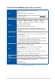
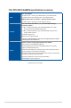
TUF Z370-PRO GAMING specifications summary LGA1151 socket for 8th Gen Intel® Core™ Processor Supports 14nm CPU CPU Supports Intel® Turbo Boost Technology 2.0* * Support of these features depends on the CPU types. Refer to www.asus.com for Intel® CPU support list. Chipset Intel® Z370 Chipset 4 x DIMM, max. 64GB, DDR4 4000(O.C.)* / 3866(O.C.)* / 3733(O.C.)* / 3600(O.C.)* / 3466(O.C.)* / 3400(O.C.)* / 3333(O.C.)* / 3300(O.C.)* / 3200(O.C.)* / 3000(O.C.)* / 2800(O.C.
TUF Z370-PRO GAMING specifications summary Intel® Z370 Chipset - 8 x USB 3.1 Gen 1 ports (4 ports @mid-board, 4 ports @back panel) USB - 6 x USB 2.0 ports (4 ports @mid-board, 2 ports @back panel) ASMedia USB 3.1 Gen 2 controllers - supports 3A power output - 2 x USB 3.1 Gen 2 ports @rear panel (teal blue, Type-A) Intel® Z370 Chipset with RAID 0, 1, 5, 10 and Intel Rapid Storage Technology support - 1 x M.
TUF Z370-PRO GAMING specifications summary TUF Components (TUF Cap, TUF Chokes, MOSFET & LANGuard; certified by military standard) ASUS SafeSlot ASUS TUF Protection - ASUS SafeSlot Core: Fortified PCIe with solid soldering - ASUS ESD Guard: Enhanced ESD protection - ASUS Overvoltage Protection: World-class circuit-protecting power design - ASUS Stainless-Steel Back I/O: 3X corrosion-resistance for greater durability! - ASUS DIGI+ VRM: 4+2 Phase digital power design Superb Performance Turbo LAN - Experienc
TUF Z370-PRO GAMING specifications summary ASUS Quiet Thermal Solution Quiet Thermal Design: - ASUS Fan Xpert 4 Core - Stylish Fanless Design: PCH Heat-sink & MOS Heat-sink 1 x DVI-D port 1 x HDMI port 1 x PS/2 combo port Back Panel I/O Ports 1 x Optical S/PDIF out 1 x Intel LAN (RJ45) port 2 x USB 3.1 Gen 2 ports (teal blue, Type A) 4 x USB 3.1 Gen 1 ports 2 x USB 2.0 ports 8-channel Audio I/O ports 2 x USB 3.1 Gen 1 connectors support additional 4 USB ports (19-pin) 2 x USB 2.
TUF Z370-PRO GAMING specifications summary BIOS 128 Mb Flash ROM, UEFI AMI BIOS, PnP, DMI3.0, WfM2.0, SM BIOS 3.0, ACPI 6.0, Multi-language BIOS, ASUS EZ Flash 3, CrashFree BIOS 3, F11 EZ Tuning Wizard, F6 Qfan Control, F3 My Favorites, Last Modified log, F12 PrintScreen, and ASUS DRAM SPD (Serial Presence Detect) memory information. Manageability WfM 2.0, DMI 3.
Package contents Check your motherboard package for the following items: Motherboard 1 x ASUS TUF Z370-PRO GAMING motherboard Cables 2 x Serial ATA 6.0 Gb/s cables 1 x ASUS SLI HB BRIDGE (2-WAY-M) 1 x IO Shield Accessories 1 x Q-Connector 2 x M.2 Screw Package 1 x CPU Installation Tool 1 x TUF GAMING sticker Application DVD Documentation 1 x Motherboard support DVD 1 x User guide 1 x TUF Certification card(s) If any of the above items is damaged or missing, contact your retailer.
Installation tools and components Graphics card (optional) Phillips (cross) screwdriver PC chassis Power supply unit Intel® LGA1151 CPU Intel® LGA1151 compatible CPU Fan DIMM SATA hard disk drive SATA optical disc drive (optional) The tools and components in the table above are not included in the motherboard package.
xvi
Product Introduction Product Introduction 1.1 Motherboard overview 1.1.1 Before you proceed 1 Chapter 1 Chapter 1: Take note of the following precautions before you install motherboard components or change any motherboard settings. • Unplug the power cord from the wall socket before touching any component. • Before handling components, use a grounded wrist strap or touch a safely grounded object or a metal object, such as the power supply case, to avoid damaging them due to static electricity.
1.1.2 Motherboard layout Chapter 1 Refer to 1.1.9 Internal connectors and 2.2.1 Rear I/O connection for more information about rear panel connectors and internal connectors.
Layout contents ASUS TUF Z370-PRO GAMING Page 1-18 1-4 1-17 Chapter 1 Connectors/Jumpers/Buttons and switches/Slots 1. ATX power connectors (24-pin EATXPWR; 8-pin EATX12V) 2. LGA1151 CPU socket 3. CPU, CPU optional, AIO pump, and chassis fan connectors (4-pin CPU_FAN; 4-pin CPU_OPT; 4-pin AIO_PUMP; 4-pin CHA_FAN1-2) 4. DDR4 DIMM slots 5. MemOK! button 6. CPU Over Voltage jumper (3-pin CPU_OV) 7. USB 3.1 Gen 1 connectors (20-1 pin U31G1_56; U31G1_78) 8. M.2 sockets (M.2_1(SOCKET3); M.2_2(SOCKET 3)) 9.
1.1.3 Central Processing Unit (CPU) The motherboard comes with a surface mount LGA1151 socket designed for the 8th Generation Intel® Core™ processors. Chapter 1 1-4 • Ensure that all power cables are unplugged before installing the CPU. • Upon purchase of the motherboard, ensure that the PnP cap is on the socket and the socket contacts are not bent. Contact your retailer immediately if the PnP cap is missing, or if you see any damage to the PnP cap/socket contacts/motherboard components.
1.1.4 System memory Chapter 1 The motherboard comes with four DDR4 (Double Data Rate 4) Dual Inline Memory Modules (DIMM) slots. A DDR4 module is notched differently from a DDR, DDR2, or DDR3 module. DO NOT install a DDR, DDR2, or DDR3 memory module to the DDR4 slot.
Memory configurations You may install 2 GB, 4 GB, 8 GB and 16 GB unbuffered and non‑ECC DDR4 DIMMs into the DIMM sockets. Chapter 1 1-6 • You may install varying memory sizes in Channel A and Channel B. The system maps the total size of the lower-sized channel for the dual-channel configuration. Any excess memory from the higher-sized channel is then mapped for single-channel operation.
1.1.5 Expansion slots Chapter 1 Unplug the power cord before adding or removing expansion cards. Failure to do so may cause you physical injury and damage motherboard components. Slot No. Slot Description 1 PCIE 3.0/2.0 x1_1 slot 2 PCIE 3.0/2.0 x16_1 slot 3 PCIE 3.0/2.0 x1_2 slot 4 PCIE 3.0/2.0 x16_2 slot 5 PCIE 3.0/2.0 x1_3 slot 6 PCIE 3.0/2.
PCI Express 3.0 operating mode VGA configuration Chapter 1 Single VGA/PCIe card Dual VGA/PCIe card PCIe 3.0/2.0 x16_2 x16 (single VGA recommended) N/A x8 x8 • We recommend that you provide sufficient power when running CrossFireX™ or SLI® mode. • Connect chassis fans to the motherboard chassis fan connectors when using multiple graphics cards for better thermal environment. Hyper M.2 X16 card configuration PCI Express 3.0 operating mode PCIe 3.0/2.0 x16_1 PCIe 3.0/2.
1.1.6 Onboard buttons and switches 1. Chapter 1 Onboard buttons and switches allow you to fine-tune performance when working on a bare or open-case system. This is ideal for overclockers and gamers who continually change settings to enhance system performance. MemOK! button Installing DIMMs that are not compatible with the motherboard may cause system boot failure.
1.1.7 1. Jumpers Clear RTC RAM jumper (2-pin CLRTC) Chapter 1 This jumper allows you to clear the Real Time Clock (RTC) RAM in CMOS. You can clear the CMOS memory of date, time, and system setup parameters by erasing the CMOS RTC RAM data. The onboard button cell battery powers the RAM data in CMOS, which include system setup information such as system passwords. To erase the RTC RAM: 1. Turn OFF the computer and unplug the power cord. 2.
2. CPU Over Voltage jumper (3-pin CPU_OV) ASUS TUF Z370-PRO GAMING Chapter 1 The CPU Over Voltage jumper allows you to set a higher CPU voltage for a flexible overclocking system, depending on the type of the installed CPU. To gain more CPU voltage setting, insert the jumper to pins 2-3. To go back to its default CPU voltage setting, insert the jumper to pins 1-2.
1.1.8 1. Onboard LEDs POST State LEDs Chapter 1 The POST State LEDs provide the status of these key components during POST (Power-On Self-Test): CPU, memory modules, VGA card, and hard disk drives. If an error is found, the critical component’s LED stays lit up until the problem is solved. The order which the LEDs light up may vary per CPU. The POST State LEDs provide the most probable cause of an error code as a starting point for troubleshooting. The actual cause may vary from case to case. 2.
1.1.9 1. Internal connectors Intel® Serial ATA 6 Gb/s connectors (7-pin SATA6G_1-6) Chapter 1 These connectors connect to Serial ATA 6 Gb/s hard disk drives via Serial ATA 6 Gb/s signal cables. If you installed Serial ATA hard disk drives, you can create a RAID 0, 1, 5, and 10 configuration with the Intel® Rapid Storage Technology through the onboard Intel® Z370 chipset. These connectors are set to [AHCI Mode] by default.
2. Front panel audio connector (10-1 pin AAFP) This connector is for a chassis-mounted front panel audio I/O module that supports HD Audio. Connect one end of the front panel audio I/O module cable to this connector. Chapter 1 We recommend that you connect a high-definition front panel audio module to this connector to avail of the motherboard’s high-definition audio capability.
3. USB 3.1 Gen 1 connectors (20-1 pin U31G1_56; U31G1_78) Chapter 1 This connector allows you to connect a USB 3.1 Gen 1 module for additional USB 3.1 Gen 1 front or rear panel ports. With an installed USB 3.1 Gen 1 module, you can enjoy all the benefits of USB 3.1 Gen 1 including faster data transfer speeds of up to 5 Gb/s, faster charging time for USB-chargeable devices, optimized power efficiency, and backward compatibility with USB 2.0. The USB 3.1 Gen 1 module is purchased separately.
4. USB 2.0 connectors (10-1 pin USB910; USB1112) Chapter 1 These connectors are for USB 2.0 ports. Connect the USB module cable to these connectors, then install the module to a slot opening at the back of the system chassis. This USB connector complies with USB 2.0 specification that supports up to 480 Mb/s connection speed. DO NOT connect a 1394 cable to the USB connectors. Doing so will damage the motherboard! The USB 2.0 module is purchased separately.
5. CPU, CPU optional, AIO pump, and chassis fan connectors (4-pin CPU_FAN; 4-pin CPU_OPT; 4-pin AIO_PUMP; 4-pin CHA_FAN1-2) Chapter 1 Connect the fan cables to the fan connectors on the motherboard, ensuring that the black wire of each cable matches the ground pin of the connector. • DO NOT forget to connect the fan cables to the fan connectors. Insufficient air flow inside the system may damage the motherboard components.
6. ATX power connectors (24-pin EATXPWR; 8-pin EATX12V) These connectors are for ATX power supply plugs. The power supply plugs are designed to fit these connectors in only one orientation. Find the proper orientation and push down firmly until the connectors completely fit. Chapter 1 1-18 • For a fully configured system, we recommend that you use a power supply unit (PSU) that complies with ATX 12 V Specification 2.0 (or later version) and provides a minimum power of 350 W.
7. System panel connector (20-3 pin PANEL) Chapter 1 This connector supports several chassis-mounted functions. • System power LED (2-pin or 3-1 pin PLED) The 2-pin or 3-1 pin connector is for the system power LED. Connect the chassis power LED cable to this connector. The system power LED lights up when you turn on the system power, and blinks when the system is in sleep mode. • Hard disk drive activity LED (2-pin HDD_LED) This 2-pin connector is for the HDD Activity LED.
8. TPM connector (14-1 pin TPM) This connector supports a Trusted Platform Module (TPM) system, which securely stores keys, digital certificates, passwords and data. A TPM system also helps enhance network security, protect digital identities, and ensures platform integrity. Chapter 1 The TPM module is purchased separately.
9. M.2 sockets (M.2_1(SOCKET 3); M.2_2(SOCKET 3)) Chapter 1 These sockets allow you to install M.2 SSD modules. • M.2_1 socket supports PCIe 3.0 x4 and SATA mode M Key design and type 2242 / 2260 / 2280 / 22110 PCIe and SATA storage devices. • M.2_2 socket supports PCIe 3.0 x4 M Key design and type 2242 / 2260 / 2280 PCIe storage devices. • These sockets support IRST (Intel® Rapid Storage Technology). The M.2 SSD module is purchased separately.
10. Serial port connector (10-1 pin COM) This connector is for a serial (COM) port. Connect the serial port module cable to this connector, then install the module to a slot opening at the back of the system chassis. Chapter 1 The COM module is purchased separately.
Chapter 2: 2 Basic Installation Basic Installation 2.1 Building your PC system The diagrams in this section are for reference only. The motherboard layout may vary with models, but the installation steps are the same for all models. 2.1.1 CPU installation Chapter 2 Ensure that you install the correct CPU designed for LGA1151 socket only. DO NOT install a CPU designed for LGA1155 and LGA1156 sockets on the LGA1151 socket.
Top of CPU Chapter 2 2-2 • The CPU Installation Tool is only compatible on ASUS motherboards with a Intel® LGA1151 socket. • Ensure that the CPU is firmly clicked into place before installing it onto the CPU socket on the motherboard. • Use the CPU Installation Tool for installing the CPU only. DO NOT damage or bend the CPU Installation Tool. • Always firmly hold both sides of the CPU Installation Tool when installing, removing, or picking up the CPU Installation Tool.
2.1.2 CPU heatsink and fan assembly installation Apply the Thermal Interface Material to the CPU heatsink and CPU before you install the heatsink and fan, if necessary.
To uninstall the CPU heatsink and fan assembly Chapter 2 2-4 Chapter 2: Basic Installation
Motherboard installation 1. Install the IO Shield to the chassis rear I/O panel. 2. Place the motherboard into the chassis, ensuring that its rear I/O ports are aligned to the chassis’ rear I/O panel. ASUS TUF Z370-PRO GAMING Chapter 2 2.1.
3. Place nine screws into the holes indicated by circles to secure the motherboard to the chassis. Chapter 2 DO NOT overtighten the screws! Doing so can damage the motherboard.
DIMM installation Chapter 2 2.1.
2.1.5 ATX power connection Chapter 2 Ensure to connect the 8-pin power plug.
2.1.
2.1.7 Front I/O connector To install ASUS Q-Connector Chapter 2 To install USB 2.0 connector To install front panel audio connector AAFP USB 2.0 To install USB 3.1 Gen 1 connector USB 3.
2.1.
2.1.9 M.2 installation Chapter 2 Supported M.2 type varies per motherboard.
Motherboard rear and audio connections 2.2.1 Rear I/O connection Chapter 2 2.2 Rear panel connectors 1. USB 2.0 ports 13 and 14 6. HDMI port 2. DVI-D port 7. USB 3.1 Gen 1 ports 1 and 2 3. USB 3.1 Gen 2 ports 8. USB 3.1 Gen 1 ports 3 and 4 4. PS/2 combo port 9. Optical S/PDIF Out port 5. Intel® LAN port* 10. Audio I/O ports** * and ** : Refer to the tables on the next page for LAN port LEDs and audio port definitions. • USB 3.
* LAN ports LED indications Activity Link LED Speed LED Status Description Status Description Off No link Off Orange Linked Orange 100 Mbps connection Orange (Blinking) Data activity Orange (Blinking then steady) Green 10 Mbps connection ACT/LINK LED SPEED LED 1 Gbps connection Ready to wake up from S5 mode LAN port You can disable the LAN controllers in BIOS. Due to hardware design, the LAN1 port’s LEDs may continue to blink even when disabled.
2.2.
Connect to 4 Speakers Connect to 6 Speakers Chapter 2 Connect to 8 Speakers 2-16 Chapter 2: Basic Installation
2.3 Starting up for the first time 1. After making all the connections, replace the system case cover. 2. Ensure that all switches are off. 3. Connect the power cord to the power connector at the back of the system chassis. 4. Connect the power cord to a power outlet that is equipped with a surge protector. 5. Turn on the devices in the following order: Monitor b. External SCSI devices (starting with the last device on the chain) c.
Chapter 2 2-18 Chapter 2: Basic Installation
Chapter 3: BIOS Setup BIOS Setup 3.1 Knowing BIOS 3 The new ASUS UEFI BIOS is a Unified Extensible Interface that complies with UEFI architecture, offering a user-friendly interface that goes beyond the traditional keyboardonly BIOS controls to enable a more flexible and convenient mouse input. You can easily navigate the new UEFI BIOS with the same smoothness as your operating system. The term “BIOS” in this user manual refers to “UEFI BIOS” unless otherwise specified.
3.2 BIOS setup program Use the BIOS Setup to update the BIOS or configure its parameters. The BIOS screen include navigation keys and brief onscreen help to guide you in using the BIOS Setup program. Entering BIOS at startup To enter BIOS Setup at startup, press or during the Power-On Self Test (POST). If you do not press or , POST continues with its routines. Entering BIOS Setup after POST To enter BIOS Setup after POST: • Press ++ simultaneously.
3.2.1 EZ Mode By default, the EZ Mode screen appears when you enter the BIOS setup program. The EZ Mode provides you an overview of the basic system information, and allows you to select the display language, system performance, mode and boot device priority. To access the Advanced Mode, select Advanced Mode or press the hotkey for the advanced BIOS settings. The default screen for entering the BIOS setup program can be changed. Refer to the Setup Mode item in section Boot menu for details.
3.2.2 Advanced Mode The Advanced Mode provides advanced options for experienced end-users to configure the BIOS settings. The figure below shows an example of the Advanced Mode. Refer to the following sections for the detailed configurations. To switch from EZ Mode to Advanced Mode, click Advanced Mode(F7) or press the hotkey.
Menu bar The menu bar on top of the screen has the following main items: My Favorites For saving the frequently-used system settings and configuration Main For changing the basic system configuration Ai Tweaker For changing the overclocking settings Advanced For changing the advanced system settings Monitor For displaying the system temperature, power status, and changing the fan settings Boot For changing the system boot configuration Tool For configuring options for special functions Exit F
Search on FAQ Move your mouse over this button to show a QR code, scan this QR code on your mobile device to connect to the BIOS FAQ web page of the ASUS support website. You can also scan the following QR code: Hot Keys This button above the menu bar contains the navigation keys for the BIOS setup program. Use the navigation keys to select items in the menu and change the settings. Scroll bar A scroll bar appears on the right side of a menu screen when there are items that do not fit on the screen.
3.2.3 QFan Control The QFan Control allows you to set a fan profile or manually configure the operating speed of your CPU and chassis fans.
Configuring fans manually Select Manual from the list of profiles to manually configure your fans’ operating speed. Speed points Select to manually configure your fans To configure your fans: Chapter 3 3-8 1. Select the fan that you want to configure and to view its current status. 2. Click and drag the speed points to adjust the fans’ operating speed. 3. Click Apply to save the changes then click Exit (ESC).
3.2.4 EZ Tuning Wizard EZ Tuning Wizard allows you to easily overclock your CPU and DRAM, computer usage, and CPU fan to their best settings. You can also set RAID in your system using this feature. OC setup RAID setup OC Tuning 1. Press on your keyboard or click EZ Tuning Wizard(F11) from the BIOS screen to open EZ Tuning Wizard screen. 2. Click OC then click Next. 3. Select a PC scenario Daily Computing or Gaming/Media Editing, then click Next.
4. Select a Main Cooling System BOX cooler, Tower cooler, Water cooler, or I’m not sure, then click Next. 5. After selecting the Main Cooling System, click Next then click Yes to start the OC Tuning. Creating RAID To create RAID: 1. Press on your keyboard or click EZ Tuning Wizard(F11) from the BIOS screen to open EZ Tuning Wizard screen. 2. Click RAID then click Yes to enable RAID. 3. • Ensure that your HDDs have no existing RAID volumes.
4. Select the type of storage for your RAID, Easy Backup or Super Speed, then click Next. a. For Easy Backup, click Next then select from Easy Backup (RAID 1) or Easy Backup (RAID 10). b. Chapter 3 You can only select Easy Backup (RAID 10) if you connect four (4) HDDs. For Super Speed, click Next then select from Super Speed (RAID 0) or Super Speed (RAID 5). 5. After selecting the type of RAID, click Next then click Yes to continue the RAID setup. 6.
3.3 My Favorites My Favorites is your personal space where you can easily save and access your favorite BIOS items. My Favorites comes with several performance, power saving, and fast boot related items by default. You can personalize this screen by adding or removing items.
Adding items to My Favorites To add BIOS items: 1. Press on your keyboard or click MyFavorite(F3) from the BIOS screen to open Setup Tree Map screen. 2. On the Setup Tree Map screen, select the BIOS items that you want to save in My Favorites screen. Main menu panel Selected shortcut items Submenu panel Delete all favorite items Recover to default favorite items 3.
3.4 Main menu The Main menu screen appears when you enter the Advanced Mode of the BIOS Setup program. The Main menu provides you an overview of the basic system information, and allows you to set the system date, time, language, and security settings. Security The Security menu items allow you to change the system security settings. 3.5 • If you have forgotten your BIOS password, erase the CMOS Real Time Clock (RTC) RAM to clear the BIOS password. See section 1.1.
The following item appears only when you set the Ai Overclocking Tuner to [Manual]. BCLK Frequency This item allows you to set the BCLK (base clock) frequency to enhance the system performance. Use the <+> or <-> to adjust the value. The values range from 98.0 MHz to 538.25 MHz. We recommend you to set the value based on the CPU specification, as high BCLK frequencies may damage the CPU permanently.
3.6 Advanced menu The Advanced menu items allow you to change the settings for the CPU and other system devices. Be cautious when changing the settings of the Advanced menu items. Incorrect field values can cause the system to malfunction. 3.6.1 CPU Configuration The items in this menu show the CPU-related information that the BIOS automatically detects. The items in this menu may vary based on the CPU installed.
3.6.3 System Agent (SA) Configuration The items in this menu allow you to adjust the Link Speed for PEG Port and Multi-Monitor. 3.6.4 PCH Configuration The items in this menu allow you to adjust the PCH PCI Express speed. PCI Express Configuration This item allows you to configure the PCI Express slots. PCIe Speed This item allows your system to automatically select the PCI Express port speed. Configuration options: [Auto] [Gen1] [Gen2] [Gen3] 3.6.
SMART Status Check SMART (Self-Monitoring, Analysis and Reporting Technology) is a monitoring system that shows a warning message during POST (Power-on Self Test) when an error occurs in the hard disks. Configuration options: [On] [Off] SATA6G_1(Gray) - SATA6G_6(Gray) SATA6G_1(Gray) - SATA6G_6(Gray) This item allows you to enable or disable the selected SATA port.
3.6.7 Onboard Devices Configuration The items in this menu allow you to switch between PCIe Lanes and configure onboard devices. Hyper M.2 X16 [Disabled] Only one SSD installed onto the Hyper M.2 X16 card can be detected. [Enabled] Two or three SSDs installed onto the Hyper M.2 X16 card can be detected. The number of SSDs that can be detected varies with the configurations of the PCIe X16 slots. HD Audio Controller This item allows you to use the Azalia High Definition Audio Controller.
3.6.8 APM Configuration The items in this menu allow you to set system wake and sleep settings. ErP Ready [Disabled] This item allows you to switch off some power at S4+S5 or S5 to get the system ready for ErP requirement. When set to [Enabled], all other PME options are switched off. Configuration options: [Disabled] [Enable(S4+S5)] [Enable(S5)] 3.6.9 Network Stack Configuration The items in this menu allow you to configure Ipv4 / Ipv6 PXE support. 3.6.
3.7 Monitor menu The Monitor menu displays the system temperature/power status, and allows you to change the fan settings. Q-Fan Configuration Q-Fan Tuning Click this item to automatically detect the lowest speed and configure the minimum duty cycle for each fan. AIO PUMP Control [Disabled] Disable the AIO Pump control feature. [Auto] Detects the type of AIO Pump installed and automatically switches the control modes. [DC mode] Enable the AIO Pump control in DC mode for 3-pin chassis fan.
CSM (Compatibility Support Module) This item allows you to configure the CSM (Compatibility Support Module) items to fully support the various VGA, bootable devices and add-on devices for better compatibility. Launch CSM [Auto] The system automatically detects the bootable devices and the addon devices. [Enabled] For better compatibility, enable the CSM to fully support the non-UEFI driver add-on devices or the Windows® UEFI mode.
Boot Option Priorities These items specify the boot device priority sequence from the available devices. The number of device items that appears on the screen depends on the number of devices installed in the system. • To access Windows® OS in Safe Mode, press after POST (Windows® 8 not supported). • To select the boot device during system startup, press when the ASUS Logo appears. Boot Override These items displays the available devices.
3.9.2 Secure Erase SSD speeds may lower over time as with any storage medium due to data processing. Secure Erase completely and safely cleans your SSD, restoring it to factory performance levels. Secure Erase is only available in AHCI mode. Ensure to set the SATA mode to AHCI. Click Advanced > PCH Storage Configuration > SATA Mode Selection > AHCI. To launch Secure Erase, click Tool > Secure Erase on the Advanced mode menu. Check the ASUS support site for a full list of SSDs tested with Secure Erase.
3.9.3 ASUS Overclocking Profile This item allows you to store or load multiple BIOS settings. Load from Profile This item allows you to load the previous BIOS settings saved in the BIOS Flash. Key in the profile number that saved your BIOS settings, press , and then select Yes. • DO NOT shut down or reset the system while updating the BIOS to prevent the system boot failure! • We recommend that you update the BIOS file only coming from the same memory/ CPU configuration and BIOS version.
3.10 Exit menu The Exit menu items allow you to load the optimal default values for the BIOS items, and save or discard your changes to the BIOS items. You can access the EZ Mode from the Exit menu. Load Optimized Defaults This option allows you to load the default values for each of the parameters on the Setup menus. When you select this option or if you press , a confirmation window appears. Select OK to load the default values.
3.11 Updating BIOS The ASUS website publishes the latest BIOS versions to provide enhancements on system stability, compatibility,and performance. However, BIOS updating is potentially risky. If there is no problem using the current version of BIOS, DO NOT manually update the BIOS. Inappropriate BIOS updating may result to system’s failure to boot. Carefully follow the instructions in this chapter to update your BIOS when necessary. Visit http://www.asus.
3.11.2 ASUS EZ Flash 3 ASUS EZ Flash 3 allows you to download and update to the latest BIOS through the Internet without having to use a bootable floppy disk or an OS‑based utility. Updating through the Internet varies per region and Internet conditions. Check your local Internet connection before updating through the Internet. To update the BIOS by USB: Chapter 3 3-28 1. Enter the Advanced Mode of the BIOS setup program. Go to the Tool menu to select ASUS EZ Flash 3 Utility and press . 2.
• This function can support devices such as a USB flash disk with FAT 32/16 format and single partition only. • DO NOT shut down or reset the system while updating the BIOS to prevent system boot failure! Ensure to load the BIOS default settings to ensure system compatibility and stability. Select the Load Optimized Defaults item under the Exit menu. See section 3.10 Exit menu for details. 1. Enter the Advanced Mode of the BIOS setup program.
3.11.3 ASUS CrashFree BIOS 3 The ASUS CrashFree BIOS 3 utility is an auto recovery tool that allows you to restore the BIOS file when it fails or gets corrupted during the updating process. You can restore a corrupted BIOS file using the motherboard support DVD or a USB flash drive that contains the BIOS file. The BIOS file in the motherboard support DVD may be older than the BIOS file published on the ASUS official website. If you want to use the newer BIOS file, download the file at https://www.asus.
Chapter 4: RAID Support RAID Support 4.1 RAID configurations 4 The motherboard supports Intel® Rapid Storage Technology with RAID 0, RAID 1, RAID 5, and RAID 10 solution. If you want to install a Windows® operating system to a hard disk drive included in a RAID set, you have to create a RAID driver disk and load the RAID driver during OS installation. Refer to section 4.2 Creating a RAID driver disk for details. 4.1.
4.1.2 Installing storage devices The motherboard supports Serial ATA hard disk drives and PCIE SSD storage devices. For optimal performance, install identical drives of the same model and capacity when creating a disk array. Refer to Chapter 2 for details on installing storage devices to your motherboard. 4.1.3 Intel® Rapid Storage Technology in UEFI BIOS To enter the Intel® Rapid Storage Technology in UEFI BIOS: 1. Enter the BIOS Setup during POST. 2.
Creating a RAID set To create a RAID set: From the Intel® Rapid Storage Technology menu, select Create RAID Volume and press . The following screen appears: 2. When the Name item is selected, enter a name for the RAID set and press . 3. When the RAID Level item is selected, press to select the RAID level to create, and then press . 4. Under Select Disks, press and select X for the disks you want to include in the RAID set. Chapter 4 1.
5. When the Strip Size item is selected, press to select strip size for the RAID array (for RAID 0, 10 and 5 only), and then press . The available strip size values range from 4 KB to 128 KB. The following are typical values: - RAID 0: 128 KB - RAID 10: 64 KB - RAID 5: 64 KB We recommend a lower strip size for server systems, and a higher strip size for multimedia computer systems used mainly for audio and video editing. 6.
Deleting a RAID set Be cautious when deleting a RAID set. You will lose all data on the hard disk drives when you delete a RAID set. To delete a RAID set: From the Intel® Rapid Storage Technology menu, select the RAID volume you want to delete and press . The following screen appears: 2. When the Delete item is selected, press , then select Yes to delete the RAID volume and return to the Intel® Rapid Storage Technology menu, or select No to cancel. Chapter 4 1.
4.1.4 Intel® Rapid Storage Technology Option ROM utility To enter the Intel® Rapid Storage Technology Option ROM utility: 1. Turn on the system. 2. During POST, press + to display the utility main menu. RAID Volumes: None defined. Physical Devices: Port Device Model 0 ST3160812AS 1 ST3160812AS 2 ST3160812AS 3 ST3160812AS Serial # 9LS0HJA4 9LS0F4HL 3LS0JYL8 9LS0BJ5H Size 149.0GB 149.0GB 149.0GB 149.
Creating a RAID set To create a RAID set: 1. From the utility main menu, select 1. Create RAID Volume and press . The following screen appears: Name: Volume 0 RAID Level: aaaaaaaaaaaaaaa Disks: dssdsdsds Strip Size:aaaaaaaaaaaaaaaa Capacity:aaaaaaaaaaaaaa Sync:aaaaaaaaaa Create volume [HELP] Enter a unique volume name that has no special characters and is 16 characters or less. 2. Enter a name for the RAID set and press . 3.
5. Use the up/down arrow key to select a drive, and then press to select. A small triangle marks the selected drive. Press after completing your selection. 6. Use the up/down arrow key to select the strip size for the RAID array (for RAID 0, 10 and 5 only), and then press . The available strip size values range from 4 KB to 128 KB.
Deleting a RAID set Be cautious when deleting a RAID set. You will lose all data on the hard disk drives when you delete a RAID set. To delete a RAID set: 1. From the utility main menu, select 2. Delete RAID Volume and press . The following screen appears: Name Volume0 [DELETE VOLUME MENU] Level Drives RAID0 (Stripe) 2 Capacity 298.0GB Status Normal Bootable Yes [HELP] Deleting a volume will reset the disks to non-RAID. WARNING: ALL DISK DATA WILL BE DELETED.
Exiting the Intel® Rapid Storage Technology Option ROM utility To exit the utility: 1. From the utility main menu, select 6. Exit, then press . The following warning message appears: [CONFIRM EXIT] Are you sure you want to exit? (Y/N): 2. Press to exit or press to return to the utility main menu. 4.2 Creating a RAID driver disk 4.2.1 Creating a RAID driver disk in Windows® To install the RAID driver for Windows® OS: 1.
Appendix Appendix Appendix Notices Federal Communications Commission Statement This device complies with Part 15 of the FCC Rules. Operation is subject to the following two conditions: • This device may not cause harmful interference. • This device must accept any interference received including interference that may cause undesired operation. This equipment has been tested and found to comply with the limits for a Class B digital device, pursuant to Part 15 of the FCC Rules.
Compliance Statement of Innovation, Science and Economic Development Canada (ISED) Appendix This Class B digital apparatus complies with Canadian ICES-003, RSS-210, and CAN ICES3(B)/NMB-3(B). This device complies with Industry Canada license exempt RSS standard(s). Operation is subject to the following two conditions: (1) this device may not cause interference, and (2) this device must accept any interference, including interference that may cause undesired operation of the device.
REACH Appendix Complying with the REACH (Registration, Evaluation, Authorisation, and Restriction of Chemicals) regulatory framework, we published the chemical substances in our products at ASUS REACH website at http://csr.asus.com/english/REACH.htm. DO NOT throw the motherboard in municipal waste. This product has been designed to enable proper reuse of parts and recycling.
Appendix English ASUSTeK Computer Inc. hereby declares that this device is in compliance with the essential requirements and other relevant provisions of related Directives. Full text of EU declaration of conformity is available at: www.asus.com/support Français AsusTek Computer Inc. déclare par la présente que cet appareil est conforme aux critères essentiels et autres clauses pertinentes des directives concernées.
ASUS contact information ASUSTeK COMPUTER INC. Appendix Address 4F, No. 150, Li-Te Road, Peitou, Taipei 112, Taiwan Telephone +886-2-2894-3447 Fax +886-2-2890-7798 Web site www.asus.com Technical Support Telephone +86-21-38429911 Fax +86-21-5866-8722, ext. 9101# Online support http://qr.asus.com/techserv ASUS COMPUTER INTERNATIONAL (America) Address 800 Corporate Way, Fremont, CA 94539, USA Telephone +1-510-739-3777 Fax +1-510-608-4555 Web site http://www.asus.
Appendix DECLARATION OF CONFORMITY Compliance Information Statement Per FCC Part 2 Section 2. 1077(a) Responsible Party Name: Asus Computer International 800 Corporate Way, Fremont, CA 94539. Address: Phone/Fax No: (510)739-3777/(510)608-4555 hereby declares that the product Product Name : Motherboard Model Number : TUF Z370-PRO GAMING Conforms to the following specifications: FCC Part 15, Subpart B, Unintentional Radiators Supplementary Information: This device complies with part 15 of the FCC Rules.