Motherboard TUF Z390M-PRO GAMING
E15013 Revised Edition November 2018 Copyright© 2018 ASUSTeK COMPUTER INC. All Rights Reserved. No part of this manual, including the products and software described in it, may be reproduced, transmitted, transcribed, stored in a retrieval system, or translated into any language in any form or by any means, except documentation kept by the purchaser for backup purposes, without the express written permission of ASUSTeK COMPUTER INC. (“ASUS”).
Contents Safety information....................................................................................................... vi About this guide......................................................................................................... vii TUF Z390M-PRO GAMING specifications summary................................................ ix Package contents......................................................................................................
Chapter 3: 3.1 3.2 BIOS setup program................................................................................... 3-2 3.2.1 EZ Mode...................................................................................... 3-3 3.2.2 Advanced Mode........................................................................... 3-4 3.2.3 QFan Control............................................................................... 3-7 3.2.4 EZ Tuning Wizard....................................................
Chapter 4: 4.1 RAID Support RAID configurations................................................................................... 4-1 4.1.1 RAID definitions........................................................................... 4-1 Appendix Notices ..................................................................................................................... A-1 ASUS contact information.......................................................................................
Safety information Electrical safety • To prevent electrical shock hazard, disconnect the power cable from the electrical outlet before relocating the system. • When adding or removing devices to or from the system, ensure that the power cables for the devices are unplugged before the signal cables are connected. If possible, disconnect all power cables from the existing system before you add a device.
About this guide This user guide contains the information you need when installing and configuring the motherboard. How this guide is organized This guide contains the following parts: 1. Chapter 1: Product Introduction This chapter describes the features of the motherboard and the new technology it supports. It includes description of the switches, jumpers, and connectors on the motherboard. 2.
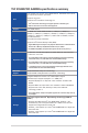
Conventions used in this guide To ensure that you perform certain tasks properly, take note of the following symbols used throughout this manual. DANGER/WARNING: Information to prevent injury to yourself when trying to complete a task. CAUTION: Information to prevent damage to the components when trying to complete a task. IMPORTANT: Instructions that you MUST follow to complete a task. NOTE: Tips and additional information to help you complete a task.
TUF Z390M-PRO GAMING specifications summary Intel® Socket 1151 for Intel® Core™ 9000 series, 8th Generation Core™ i7/ i5/ i3, Pentium® and Celeron® processors Supports 14nm CPU CPU Supports Intel® Turbo Boost Technology 2.0* * Intel® Turbo Boost Technology 2.0 support depends on the CPU types. ** Refer to www.asus.com for Intel® CPU support list. Chipset Intel® Z390 Chipset 4 x DIMM, max. 64GB, DDR4 4133(O.C.) / 4000(O.C.) / 3866(O.C.) / 3733(O.C.) / 3600(O.C.) / 3466(O.C.) / 3400(O.C.) / 3333(O.C.
TUF Z390M-PRO GAMING specifications summary Intel® Z390 Chipset with RAID 0, 1, 5, 10 and Intel Rapid Storage Technology support - 1 x M.2_1 Socket 3 with M key, type 2242/2260/2280/22110 storage devices support (both PCIE x4 & SATA modes)** Storage - 1 x M.2_2 Socket 3 with M Key, type 2242/2260/2280 storage devices support (PCIe x4 mode) - 6 x SATA 6Gb/s ports - Intel® Optane™ Memory Ready * Hyper M.2 X16 series card is sold separately. Install a Hyper M.
TUF Z390M-PRO GAMING specifications summary 1 x USB 3.1 Gen 2 (up to 10Gbps) front panel connector 1 x USB 3.1 Gen 1 connector supports additional 2 USB 3.1 Gen 1 ports (19-pin) 2 x USB 2.0 connectors support additional 4 USB 2.0 ports 6 x SATA 6Gb/s connectors 1 x M.2_1 Socket 3 for M Key, type 2242/2260/2280/22110 storage devices 1 x M.
TUF Z390M-PRO GAMING specifications summary OptiMem II - Higher performance of memory overclocking. Enhance compatibility for some memory with RGB. MemOK! II - Enhance memory compatibility. More smart and convenient. Keep high performance. (Shorten the PC starting time) Q-Installer - Auto download driver and software. Friendly for first PC builder.
Package contents Check your motherboard package for the following items. Motherboard TUF Z390M-PRO GAMING Cables 2 x SATA 6Gb/s cables 1 x IO Shield 1 x M.2 screw package (2-in-1) Accessories 1 x Q-connector 1 x SLITM HB BRIDGE (2-WAY-S) 1 x TUF GAMING sticker Application drive Documentation 1 x support DVD 1 x User guide 1 x TUF Certification card If any of the above items is damaged or missing, contact your retailer.
Installation tools and components Intel® 1151 CPU Intel® 1151 compatible CPU Fan PC chassis SATA hard disk drive Phillips (cross) screwdriver 1 bag of screws DIMM Power supply unit SATA optical disc drive (optional) Graphics card The tools and components listed above are not included in the motherboard package.
Product Introduction Product Introduction 1.1 Motherboard overview 1.1.1 Before you proceed 1 Chapter 1 Chapter 1: Take note of the following precautions before you install motherboard components or change any motherboard settings. • Unplug the power cord from the wall socket before touching any component. • Before handling components, use a grounded wrist strap or touch a safely grounded object or a metal object, such as the power supply case, to avoid damaging them due to static electricity.
1.1.2 Motherboard layout 1 2 3 2 24.4cm(9.6in) 4 Chapter 1 5 KBMS EATX12V 6 CPU_FAN DIGI+ VRM CPU_OPT 24.4cm(9.
Layout contents ASUS TUF Z390M-PRO GAMING Page 1-16 Chapter 1 Connectors/Jumpers/Buttons and switches/Slots 1. EATX power connectors (24-pin EATXPWR; 8-pin EATX12V) 2. CPU, CPU optional, and chassis fan connectors; AIO pump connector (4pin CPU_FAN; 4-pin CPU_OPT; 4-pin CHA_FAN1-2; 4-pin AIO_PUMP) 3. LGA1151 CPU socket 4. DDR4 DIMM slots 5. MemOK! II switch (MemOK!_II_switch) 6. Memory LED (Mem_LED) 7. USB 3.1 Gen 2 front panel connector (U31G2_C3) 8. M.2 sockets (M.2_1; M.2_2) 9.
1.1.3 Central Processing Unit (CPU) The motherboard comes with a surface mount LGA1151 socket designed for Intel® Core™ 9000 series, 8th Generation Core™ i7/ i5/ i3, Pentium® and Celeron® processors. ® Chapter 1 TUF Z390M-PRO GAMING CPU LGA1151 1-4 • Ensure that you install the correct CPU designed for LGA1151 socket only. DO NOT install a CPU designed for LGA1150, LGA1155, and LGA1156 sockets in the LGA1151 socket. • Ensure that all power cables are unplugged before installing the CPU.
1.1.4 System memory Chapter 1 The motherboard comes with four DDR4 (Double Data Rate 4) Dual Inline Memory Modules (DIMM) slots. DIMM_A2* DIMM_A1 DIMM_B2* ® DIMM_B1 A DDR4 module is notched differently from a DDR, DDR2, or DDR3 module. DO NOT install a DDR, DDR2, or DDR3 memory module to the DDR4 slot.
Memory configurations You may install 2 GB, 4 GB, 8 GB and 16 GB unbuffered and non‑ECC DDR4 DIMMs into the DIMM sockets. Chapter 1 You may install varying memory sizes in Channel A, and Channel B. The system maps the total size of the lower-sized channel for the dual-channel configuration. Any excess memory from the higher-sized channel is then mapped for single-channel operation.
1.1.5 Expansion slots ® Chapter 1 Unplug the power cord before adding or removing expansion cards. Failure to do so may cause you physical injury and damage motherboard components. PCIEX16_1 PCIEX16_2 PCIEX1 Slot No.
VGA Configuration Chapter 1 Single VGA/PCIe card Dual VGA/PCIe cards PCIEX16_2 x16 (single VGA recommended) N/A x8 x8 • In single VGA card mode, use the PCIEX16_1 slot (gray) for a PCI Express x16 graphics card to get better performance. • We recommend that you provide sufficient power when running CrossFireX™ or SLI™ mode. • Connect a chassis fan to the motherboard connector labeled CHA_FAN1-2 when using multiple graphics cards for better thermal environment. Hyper M.
1.1.6 1. Onboard switches MemOK! II switch (MemOK!_II) Chapter 1 Installing DIMMs that are not compatible with the motherboard may cause system boot failure. The switch is enabled by default, allowing memory re-training when the motherboard is unresponsive due to memory problems. The Mem_LED will light up while re-training, and turn off when the re-training is complete. MemOK!_II ® ON OFF TUF Z390M-PRO GAMING MemOK! switch • Refer to section 1.1.8 Onboard LEDs for the exact location of the MEM LED.
1.1.7 1. Jumpers Clear RTC RAM jumper (2-pin CLRTC) ® Chapter 1 This jumper allows you to clear the Real Time Clock (RTC) RAM in CMOS. You can clear the CMOS memory of date, time, and system setup parameters by erasing the CMOS RTC RAM data. The onboard button cell battery powers the RAM data in CMOS, which include system setup information such as system passwords. +3V_BAT GND CLRTC PIN 1 TUF Z390M-PRO GAMING Clear RTC RAM To erase the RTC RAM: 1. Turn OFF the computer and unplug the power cord.
1.1.8 1. Onboard LEDs Memory LED (Mem_LED) Chapter 1 ® The Mem_LED will light up and remain lit while the MemOK! II function is in use. When the re-training is complete, the Mem_LED will turn off.
1.1.9 1. Internal connectors Intel® Z390 Serial ATA 6 Gb/s connectors (7-pin SATA6G_1-6) Chapter 1 These connectors connect to Serial ATA 6 Gb/s hard disk drives via Serial ATA 6 Gb/s signal cables. If you installed Serial ATA hard disk drives, you can create a RAID 0, 1, 5, and 10 configuration with the Intel® Rapid Storage Technology through the onboard Intel® Z390 chipset.
2. Front panel audio connector (10-1 pin AAFP) Chapter 1 SENSE2_RETUR ® AGND NC SENSE1_RETUR This connector is for a chassis-mounted front panel audio I/O module that supports HD Audio. Connect one end of the front panel audio I/O module cable to this connector.
4. USB 3.1 Gen1 connector (20-1 pin U31G1_910) Chapter 1 This connector allows you to connect a USB 3.1 Gen1 module for additional USB 3.1 Gen1 front or rear panel ports. With an installed USB 3.1 Gen1 module, you can enjoy all the benefits of USB 3.1 Gen1 including faster data transfer speeds of up to 5 Gb/s, faster charging time for USB-chargeable devices, optimized power efficiency, and backward compatibility with USB 2.0.
6. CPU, CPU optional, and chassis fan connectors; AIO pump connector (4-pin CPU_FAN; 4-pin CPU_OPT; 4-pin CHA_FAN1-2; 4-pin AIO_PUMP) • DO NOT forget to connect the fan cables to the fan connectors. Insufficient air flow inside the system may damage the motherboard components. These are not jumpers! Do not place jumper caps on the fan connectors! • Ensure that the CPU fan cable is securely installed to the CPU fan connector.
8. EATX power connectors (24-pin EATXPWR; 8-pin EATX12V) These connectors are for ATX power supply plugs. The power supply plugs are designed to fit these connectors in only one orientation. Find the proper orientation and push down firmly until the connectors completely fit.
9. System panel connector (20-5 pin PANEL) This connector supports several chassis-mounted functions. Chapter 1 +5V Ground Ground Speaker ® PLED+ PLEDPWRBTN# GND PLED PWRSW SPEAKER PANEL PLED- HDD_LED+ HDD_LEDGround RSTCON# NC PLED+ PIN 1 HDD_LED RESET PLED TUF Z390M-PRO GAMING System panel connector • System power LED (2-pin or 3-1 pin PLED) The 2-pin or 3-1 pin connector is for the system power LED. Connect the chassis power LED cable to this connector.
10. M.2 sockets (M.2_1; M.2_2) These sockets allow you to install M.2 SSD modules. A Chapter 1 M.2_1(SOCKET3) 22110 2280 2260 2242 ® B M.2_2(SOCKET3) A 2280 2260 2242 B TUF Z390M-PRO GAMING M.2 sockets • M.2_1 socket supports PCIe 3.0 x4 and SATA modes M Key design and type 2242 / 2260 / 2280 /22110 PCIe and SATA storage devices. • M.2_2 socket supports PCIe 3.0 x4 mode M Key design and type 2242 / 2260 / 2280 PCIe storage devices. • The M.2_1 socket shares SATA_2 port when using an M.
12. RGB headers (4-pin RGB_HEADER1/2) These headers are for RGB LED strips. ® PIN 1 +12V G R B RGB_HEADER2 Chapter 1 RGB_HEADER1 PIN 1 +12V G R B TUF Z390M-PRO GAMING RGB_HEADER connectors The RGB headers support 5050 RGB multi-color LED strips (12V/G/R/B), with a maximum power rating of 3A (12V), and no longer than 3 m. Before you install or remove any component, ensure that the ATX power supply is switched off or the power cord is detached from the power supply.
Chapter 1 1-20 Chapter 1: Product Introduction
Chapter 2: Basic Installation Basic Installation 2.1 Building your PC system 2 The diagrams in this section are for reference only. The motherboard layout may vary with models, but the installation steps are the same for all models. 2.1.1 CPU installation Chapter 2 Ensure that you install the correct CPU designed for LGA1151 socket only. DO NOT install a CPU designed for LGA1155 and LGA1156 sockets on the LGA1151 socket.
Chapter 2 2-2 Chapter 2: Basic Installation
2.1.2 Cooling system installation Apply the Thermal Interface Material to the CPU cooling system and CPU before you install the cooling system, if necessary.
To install an AIO cooler Chapter 2 AIO_PUMP CPU_FAN CPU_OPT The illustrations in this section are for reference only. Please refer to section 1.1.2 Motherboard Layout for the actual location of the header(s).
Motherboard installation Place the motherboard into the chassis, ensuring that its rear I/O ports are aligned to the chassis’ rear I/O panel. 2. Place eight (8) screws into the holes indicated by circles to secure the motherboard to the chassis. ® 1. Chapter 2 2.1.3 DO NOT overtighten the screws! Doing so can damage the motherboard.
2.1.
ATX power connection Chapter 2 2.1.5 Ensure to connect the 8-pin power plug.
2.1.
2.1.7 Front I/O connector To install front panel connector To install USB 3.1 Gen2 connector USB 3.1 Gen2 To install USB 3.1 Gen 1 connector Chapter 2 This connector will only fit in one orientation. Push the connector until it clicks into place. To install USB 2.0 connector USB 3.1 Gen 1 USB 2.
2.1.
M.2 installation For type 22110 M.2 on M.2_1 socket 1 1 1 1 2 2 3 For type 2242 / 2260 / 2280 M.2 on M.2_1 socket 1 3 6 1 2 3 4 56 78 8 4 6 8 4 1 3 6 5 1 2 Chapter 2 2.1.9 8 4 7 6 6 5 5 The M.2 is purchased separately.
2.2 Motherboard rear and audio connections 2.2.1 Rear I/O connection 1 11 10 2 3 4 5 6 9 8 2 7 Chapter 2 Rear panel connectors 1. PS/2 Mouse port 2. USB 3.1 Gen 1 ports 3. USB 3.1 Gen 2 port 4. LAN (RJ-45) port* 5. Line In port** 6. Line Out port** 7. Microphone port** 8. USB 3.1 Gen 1 Type-C port 9. HDMI port 10. DisplayPort 11. PS/2 Keyboard port * and ** : Refer to the tables on the next page for LAN port LEDs, and audio port definitions. 2-12 • USB 3.
* LAN ports LED indications ACT/LINK SPEED LED LED Activity Link LED Speed LED Status Description Status Description OFF No link OFF 10 Mbps connection ORANGE Linked ORANGE 100 Mbps connection BLINKING Data activity GREEN 1 Gbps connection LAN port You can disable the LAN controllers in BIOS. Due to hardware design, the LAN port’s LEDs may continue to blink even when disabled.
2.2.
Connect to 4 Speakers Chapter 2 Connect to 6 Speakers Connect to 8 Speakers ASUS TUF Z390M-PRO GAMING 2-15
2.3 Starting up for the first time 1. After making all the connections, replace the system case cover. 2. Ensure that all switches are off. 3. Connect the power cord to the power connector at the back of the system chassis. 4. Connect the power cord to a power outlet that is equipped with a surge protector. 5. Turn on the devices in the following order: 6. a. Monitor b. External storage devices (starting with the last device on the chain) c.
Chapter 3: BIOS Setup BIOS Setup 3.1 Knowing BIOS 3 The new ASUS UEFI BIOS is a Unified Extensible Interface that complies with UEFI architecture, offering a user-friendly interface that goes beyond the traditional keyboardonly BIOS controls to enable a more flexible and convenient mouse input. You can easily navigate the new UEFI BIOS with the same smoothness as your operating system. The term “BIOS” in this user manual refers to “UEFI BIOS” unless otherwise specified.
3.2 BIOS setup program Use the BIOS Setup to update the BIOS or configure its parameters. The BIOS screen include navigation keys and brief onscreen help to guide you in using the BIOS Setup program. Entering BIOS at startup To enter BIOS Setup at startup, press or during the Power-On Self Test (POST). If you do not press or , POST continues with its routines. Entering BIOS Setup after POST To enter BIOS Setup after POST: • Press ++ simultaneously.
3.2.1 EZ Mode The EZ Mode provides you an overview of the basic system information, and allows you to select the display language, system performance, mode and boot device priority. To access the Advanced Mode, select Advanced Mode or press the hotkey for the advanced BIOS settings. The default screen for entering the BIOS setup program can be changed. Refer to the Setup Mode item in section Boot menu for details.
3.2.2 Advanced Mode The Advanced Mode provides advanced options for experienced end-users to configure the BIOS settings. The figure below shows an example of the Advanced Mode. Refer to the following sections for the detailed configurations. To switch from Advanced Mode to EZ Mode, click EZ Mode(F7) or press the hotkey.
Menu bar The menu bar on top of the screen has the following main items: My Favorites For saving the frequently-used system settings and configuration. Main For changing the basic system configuration Extreme Tweaker For changing the overclocking settings Advanced For changing the advanced system settings Monitor For displaying the system temperature, power status, and changing the fan settings.
Search (F9) This button allows you to search for BIOS items by entering its name, enter the item name to find the related item listing. AURA (F4) This button allows you to turn the RGB LED lighting or functional LED on or off. [All On]: All LEDs (Aura or Functional) will be enabled. [Aura Only]: Aura LEDs will be enabled and functional LEDs will be disabled. [Aura Off]: Aura LEDs will be disabled, however functional LEDs will still be enabled.
3.2.3 QFan Control The QFan Control allows you to set a fan profile or manually configure the operating speed of your CPU and chassis fans.
Configuring fans manually Select Manual from the list of profiles to manually configure your fans’ operating speed. Speed points Select to manually configure your fans To configure your fans: Chapter 3 3-8 1. Select the fan that you want to configure and to view its current status. 2. Click and drag the speed points to adjust the fans’ operating speed. 3. Click Apply to save the changes then click Exit (ESC).
3.2.4 EZ Tuning Wizard EZ Tuning Wizard allows you to easily overclock your CPU and DRAM, computer usage, and CPU fan to their best settings. You can also set RAID in your system using this feature. OC setup RAID setup OC Tuning To start OC Tuning: Press on your keyboard or click EZ Tuning Wizard screen. 2. Click OC then click Next. 3. Select a PC scenario Daily Computing or Gaming/Media Editing, then click Next. ASUS TUF Z390M-PRO GAMING from the BIOS screen to open Chapter 3 1.
4. Select a Main Cooling System BOX cooler, Tower cooler, Water cooler, or I’m not sure, then click Next. 5. After selecting the Main Cooling System, click Next then click Yes to start the OC Tuning. Creating RAID To create RAID: 1. Press on your keyboard or click EZ Tuning Wizard screen. 2. Click RAID then click Next. 3. Chapter 3 3-10 from the BIOS screen to open • Ensure that your HDDs have no existing RAID volumes. • Ensure to connect your HDDs to Intel® SATA connectors.
Select the type of storage for your RAID, Easy Backup or Super Speed, then click Next. a. For Easy Backup, click Next then select from Easy Backup (RAID1) or Easy Backup (RAID10). Chapter 3 4. You can only select Easy Backup (RAID 10) if you connect four (4) HDDs. b. For Super Speed, click Next then select from Super Speed (RAID0) or Super Speed (RAID5). 5. After selecting the type of RAID, click Next then click Yes to continue the RAID setup. 6.
3.3 My Favorites My Favorites is your personal space where you can easily save and access your favorite BIOS items. Chapter 3 My Favorites comes with several performance, power saving, and fast boot related items by default. You can personalize this screen by adding or removing items.
Adding items to My Favorites To add BIOS items: 1. Press on your keyboard or click MyFavorites(F3) from the BIOS screen to open Setup Tree Map screen. 2. On the Setup Tree Map screen, select the BIOS items that you want to save in My Favorites screen. Main menu panel Selected shortcut items Submenu panel Delete all favorite items Recover to default favorite items 3.
3.4 Main menu The Main menu screen appears when you enter the Advanced Mode of the BIOS Setup program. The Main menu provides you an overview of the basic system information, and allows you to set the system date, time, language, and security settings. Security The Security menu items allow you to change the system security settings. 3.5 • If you have forgotten your BIOS password, erase the CMOS Real Time Clock (RTC) RAM to clear the BIOS password. See section 1.1.
ASUS MultiCore Enhancement [Auto] Allows you to maximize the oveclocking performance optimized by ASUS core ratio settings. [Disabled] Allows you to set to default core ratio settings. [Enabled] Allows you to set the core ratio settings. CPU Core Ratio This item allows you to set the CPU core ratios. Configuration options: [Auto] [Sync All Cores] [Per Core] DRAM Frequency This item allows you to set the memory operating frequency.
3.6 Advanced menu The Advanced menu items allow you to change the settings for the CPU and other system devices. Be cautious when changing the settings of the Advanced menu items. Incorrect field values can cause the system to malfunction. 3.6.1 Platform Misc Configuration The items in this menu allow you to change the ASPM for PCH and SA PCI Express. 3.6.2 CPU Configuration The items in this menu show the CPU-related information that the BIOS automatically detects.
3.6.4 PCH Configuration The items in this menu allow you to adjust the PCH PCI Express speed. PCI Express Configuration This item allows you to configure the PCI Express slots. PCIe Speed This item allows your system to automatically select the PCI Express port speed. Configuration options: [Auto] [Gen1] [Gen2] [Gen3] 3.6.5 PCH Storage Configuration While entering Setup, the BIOS automatically detects the presence of SATA devices.
3.6.6 PCH-FW Configuration This item allows you to configure the firmware TPM. 3.6.7 Onboard Devices Configuration The items in this menu allow you to switch between PCIe Lanes and configure onboard devices. Hyper M.2X16 [Enabled][Disabled] [Disabled] Only one SSD installed onto the Hyper M.2 X16 card can be detected. [Enabled] Two or three SSDs installed onto the Hyper M.2 X16 card can be detected. The number of SSDs that can be detected varies with the configurations of the PCIe X16 slots.
3.6.10 USB Configuration The items in this menu allow you to change the USB-related features. The Mass Storage Devices item shows the auto-detected values. If no USB device is detected, the item shows None. USB Single Port Control This item allows you to enable or disable the individual USB ports. Refer to section 1.1.2 Motherboard layout for the location of the USB ports. 3.6.11 Network Stack Configuration The items in this menu allow you to configure Ipv4 / Ipv6 PXE support. 3.6.
3.7 Monitor menu The Monitor menu displays the system temperature/power status, and allows you to change the fan settings. Qfan Configuration Qfan Tuning Click this item to automatically detect the lowest speed and configure the minimum duty cycle for each fan. 3.8 Boot menu The Boot menu items allow you to change the system boot options. Boot Configuration Fast Boot [Disabled] Allows your system to go back to its normal boot speed. [Enabled] Allows your system to accelerate the boot speed.
The following items appear only when you set Launch CSM to [Enabled]. Boot Devices Control This item allows you to select the type of devices that you want to boot. Configuration options: [UEFI and Legacy OPROM] [Legacy OPROM only] [UEFI only] Boot from Network Devices This item allows you to select the type of network devices that you want to launch.
3.9 Tool menu The Tool menu items allow you to configure options for special functions. Select an item then press to display the submenu. 3.9.1 ASUS EZ Flash 3 Utility This item allows you to run ASUS EZ Flash 3. When you press , a confirmation message appears. Use the left/right arrow key to select between [Yes] or [No], then press to confirm your choice. For more details, refer to section 3.11.2 ASUS EZ Flash 3. 3.9.
3.10 Exit menu The Exit menu items allow you to load the optimal default values for the BIOS items, and save or discard your changes to the BIOS items. You can access the EZ Mode from the Exit menu. Load Optimized Defaults This option allows you to load the default values for each of the parameters on the Setup menus. When you select this option or if you press , a confirmation window appears. Select OK to load the default values.
3.11 Updating BIOS The ASUS website publishes the latest BIOS versions to provide enhancements on system stability, compatibility,and performance. However, BIOS updating is potentially risky. If there is no problem using the current version of BIOS, DO NOT manually update the BIOS. Inappropriate BIOS updating may result to system’s failure to boot. Carefully follow the instructions in this chapter to update your BIOS when necessary. Visit http://www.asus.
3.11.2 ASUS EZ Flash 3 ASUS EZ Flash 3 allows you to download and update to the latest BIOS through the Internet without having to use a bootable floppy disk or an OS‑based utility. Updating through the Internet varies per region and Internet conditions. Check your local Internet connection before updating through the Internet. 1. Enter the Advanced Mode of the BIOS setup program. Go to the Tool menu to select ASUS EZ Flash 3 Utility and press . 2.
• This function can support devices such as a USB flash disk with FAT 32/16 format and single partition only. • DO NOT shut down or reset the system while updating the BIOS to prevent system boot failure! Ensure to load the BIOS default settings to ensure system compatibility and stability. Select the Load Optimized Defaults item under the Exit menu. See section 3.10 Exit Menu for details. To update the BIOS by Internet: Enter the Advanced Mode of the BIOS setup program.
3.11.3 ASUS CrashFree BIOS 3 The ASUS CrashFree BIOS 3 utility is an auto recovery tool that allows you to restore the BIOS file when it fails or gets corrupted during the updating process. You can restore a corrupted BIOS file using the motherboard support DVD or a USB flash drive that contains the BIOS file. The BIOS file in the motherboard support DVD may be older than the BIOS file published on the ASUS official website. If you want to use the newer BIOS file, download the file at https://www.asus.
Chapter 3 3-28 Chapter 3: BIOS Setup
Chapter 4: RAID Support RAID Support 4.1 RAID configurations 4 The motherboard comes with the Intel® Rapid Storage Technology that supports RAID 0, RAID 1, RAID 5 and RAID 10 configuration. For more information on configuring your RAID sets, please refer to the RAID Configuration Guide which you can find at https://www.asus.com/support. 4.1.1 RAID definitions RAID 0 (Data striping) optimizes two identical hard disk drives to read and write data in parallel, interleaved stacks.
Chapter 4 4-2 Chapter 4: RAID Support
Appendix Appendix Notices FCC Compliance Information Responsible Party: Address: Phone / Fax No: Asus Computer International 48720 Kato Rd., Fremont, CA 94538, USA (510)739-3777 / (510)608-4555 This device complies with part 15 of the FCC Rules. Operation is subject to the following two conditions: (1) This device may not cause harmful interference, and (2) this device must accept any interference received, including interference that may cause undesired operation.
Compliance Statement of Innovation, Science and Economic Development Canada (ISED) This device complies with Innovation, Science and Economic Development Canada licence exempt RSS standard(s). Operation is subject to the following two conditions: (1) this device may not cause interference, and (2) this device must accept any interference, including interference that may cause undesired operation of the device.
REACH Complying with the REACH (Registration, Evaluation, Authorisation, and Restriction of Chemicals) regulatory framework, we published the chemical substances in our products at ASUS REACH website at http://csr.asus.com/english/REACH.htm. DO NOT throw the motherboard in municipal waste. This product has been designed to enable proper reuse of parts and recycling.
Appendix English ASUSTeK Computer Inc. hereby declares that this device is in compliance with the essential requirements and other relevant provisions of related Directives. Full text of EU declaration of conformity is available at: www.asus.com/support Français AsusTek Computer Inc. déclare par la présente que cet appareil est conforme aux critères essentiels et autres clauses pertinentes des directives concernées.
ASUS contact information ASUSTeK COMPUTER INC. Address Telephone Fax Web site Technical Support Telephone Fax Online support 4F, No. 150, Li-Te Road, Peitou, Taipei 112, Taiwan +886-2-2894-3447 +886-2-2890-7798 www.asus.com +86-21-38429911 +86-21-5866-8722, ext. 9101# http://qr.asus.com/techserv ASUS COMPUTER INTERNATIONAL (America) Address Telephone Fax Web site Technical Support Support fax Telephone Online support 48720 Kato Rd.
Appendix A-6 Appendix